Author: Chiara Bedon
Academic Editor: Rafik Belarbi
Source: Hindawi - Advances in Civil Engineering | Volume 2017 | Article ID 2120570
DOI: https://doi.org/10.1155/2017/2120570
Abstract
Architectural design concepts incorporating glass beams, panels, or generally load-carrying elements and stiffeners for buildings, claddings, windows, and partitions are largely considered in modern high-rise constructions. A multitude of aspects, including motivations related to transparency, aesthetics, illumination, and energy conservation, progressively increased the use and interest for such a still rather innovative constructional material. However, compared to other traditional materials for buildings, standard glass is typically characterized by brittle behaviour and limited tensile resistance. The intrinsic properties of glass, moreover, together with typically limited thickness-to-size ratios for glazing elements, or the mutual interaction of glass components with adjacent constructional elements as a part of full assemblies they belong (i.e., fixing systems, sealants, etc.), as well as the combination of mechanical and thermal phenomena, make glass structures highly vulnerable. Special safety design rules are hence required, especially under extreme loading conditions. In this review paper, a state of the art on structural glass systems exposed to fire is presented. Careful consideration is paid for actual design methods and general regulations, as well as for existing research outcomes—both at the material and assembly levels—giving evidence of current challenges, issues, and developments.
1. Introduction
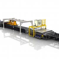
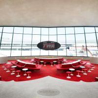
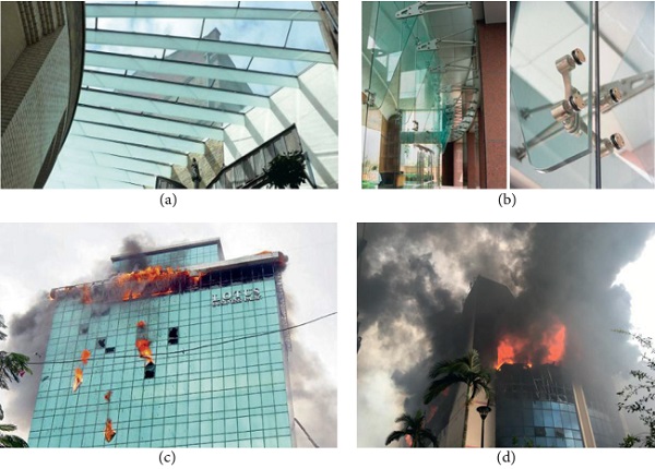
Glass is largely used in buildings as a construction material, to replace and/or interact with traditional structural elements composed of steel, aluminum, timber, and concrete. Major applications of glass in buildings are related to a multitude of aspects, including aesthetics, lightening, transparency, and insulation motivations (see, e.g., Figures 1(a) and 1(b)).
Generally, glass is known to behave as a brittle material with relatively high compressive resistance and limited tensile strength, hence shattering into many dangerous shards [1, 2]. Fail-safe design concepts, in this sense, are mandatory, both under ordinary loads and extreme loading conditions.
In this regard, several research studies have been dedicated over the last years to the development and/or assessment of specific design regulations and novel design concepts for structural glass systems, including extended experimental and finite element (FE) numerical investigations related to connections, composite assemblies, and hybrid systems [3–6].
Special care has been spent also for the analysis and design of glazing systems under extreme loads, such as explosive events [7–9], seismic loads [10–13], natural hazards and climatic loads [14, 15], fire [16, 17], and impacts [18–20].
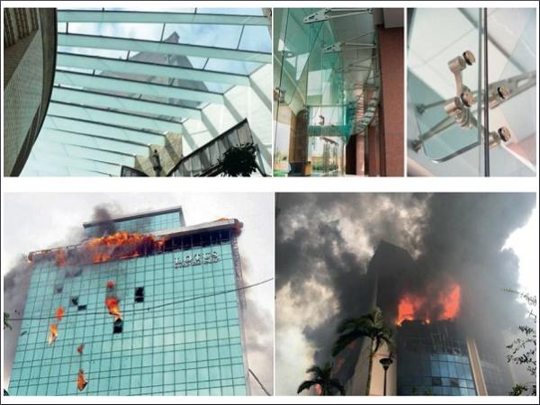
Especially in the case of fire accidents, special enhanced safety levels should in fact be ensured, to allow evacuation of buildings (Figures 1(c) and 1(d)).
Multiple aspects are however combined in the overall fire performance of a given structural glass system, such as the typical brittle behaviour of material, the high sensitivity of its mechanical properties to temperature, the high sensitivity of fire performance to geometrical features, glass type, and the mutual interactions between all the system components (i.e., the structural glass assembly, including supports and building components).
As a specific issue of glass systems, in addition, their fire performance cannot be analytically derived but requires fire testing estimations. Advanced FE modelling, in this regard, could represent a valid alternative to time- and cost-consuming experiments. However, major issues for the FE analysis of structural glass elements under fire derive from the current lack of standardized guidelines and general rules able to offer reliable results [21], as well as of well-established mechanical and thermal properties of materials in use. In addition, FE literature efforts related to the fire performance of structural glass systems are very limited (see, e.g., [22]).
In this paper, a review of experimental research on structural glass systems under fire is proposed. Section 2 first recalls a short overview of structural design concepts and requirements. In Section 3, mechanical and thermal properties of standard glass under high temperatures are reported, giving evidence of several literature source outcomes, as well as relatively recent fire-resistant (FR) glass solutions available on the market for special applications. Careful consideration is paid, in particular, for material properties representing key input parameters for structural design purposes. Sections 4 and 5 finally present a summary of existing experimental research related to the fire performance of glass to high temperatures, including material properties (Section 4) and structural glass systems (Section 5), such as floors and overheads, beams, facades and windows, and glazing systems retrofitted via protective films.
2. General Design Rules and Concepts
2.1. Structural Glass Systems under Ordinary Loads
Compared to traditional materials in use of constructions, one of the major factors affecting the design and verification of structural glass elements is represented by its intrinsic features. Even without fault of the designer, a given structural glass element can in fact break unexpectedly, during its service life [1]. Whatever the reason, the structural integrity of the overall assembly it belongs must not be compromised. According to the general design concept of EN 1990:2002 [23], both ultimate limit state (ULS) and service limit state (SLS) should be properly verified.
The ULS resistance verification is intended to fulfill the structural safety of a structural glass element [1, 2]. Such a safety assessment is generally performed by limiting the maximum principal stresses achieved under relevant load combinations to do not exceed the design resistance of glass. Multiple aspects can affect, however, the design value of glass resistance (see, e.g., [1, 2]), being defined as a function of glass type, loading (i.e., in-plane and out-of-plane), loading time (i.e., instantaneous, permanent, etc.), edge effects and treatments, glass surface treatments, profile, etc. In Europe, following the recommendations of [2, 24], several national codes adopted the same design provisions (see, e.g., [25–27]). Different approaches can be found in US regulations, while further issues also derive from a combination of effects due to multiple design actions (see, e.g., [28]).
The SLS verification is aimed at the limitation of deflections. The reference limit values for such deformations mainly depend on the specific applications or support conditions. As in the case of specifications for ULS design, different SLS limit deformation values can be found in standards. A further design condition that should be properly verified (see, e.g., the CNR guidelines [29]) is then associated to the so-called collapse limit state (CLS). Given a structural glass system to verify, in order to ensure appropriate redundancy in the case of accidental cracking, the residual CLS resistance and maximum deformations of the partially damaged system are also required.
2.2. Structural Glass Systems under Fire Loading
Fire loading represents, for glass systems as well as for constructions in general, an extreme loading configuration. As such, specific provisions should be taken into account to ensure appropriate performance levels.
Given a glazing system exposed to fire, in accordance with existing standards (see, e.g., the EN 13501-2 regulations [30]), its fire performance is generally defined on the basis of three classifications levels:
(a) integrity (classification “E”): glass prevents flames, smoke, and hot gases from passing through. The fire remains contained;
(b) limiting radiation (“EW”): glass restricts the amount of heat passing through it to the side which is to be protected;
(c) thermal insulation (“EI”): the average temperature of glass on the protected side remains below 140°C; hence, the risk of self-combustion of exposed materials (due to either radiation or convection) can be minimized, and buildings can be evacuated safely and calmly.
The above FR reference criteria can only be determined on the basis of fire experiments, and typical FR rating classes are associated to 30, 60, or 120 minutes of performance. Relevant standards in use in Europe are, for example, the EN 1363-1 document [31], providing FR test requirements and methods; EN 1364-1 [32], for non-load-bearing elements and walls; and EN 1634 [33], for doors and shutters. Floors and roofs should be indeed tested in accordance with EN 1365-2 regulations [34] and then classified by following the EN 13501-2 provisions.
In addition to EU provisions, the American Underwriters Laboratory standard [35] includes a further requirement; that is, a given FR glazing system should have the ability to withstand the so-called “hose-stream test,” which assesses the system ability to remain intact after a jet of water is blasted on its surface, when exposed to fire [36].
Compared to other extreme loading conditions which may occur over the lifetime of a given structural glazing system, the main issue of FR glass systems arises from glass response to temperature variations. Conventional glass for application in buildings (Section 3), in fact, offers typically limited resistance when exposed to fire and generally shatters within minutes, giving evidence of the so-called thermal breakage phenomena (Section 4). Heat treatment can offer slightly longer resistance, but this enhancement could not be significantly enough. Special glass types, conventionally detected as “FR glasses” or “fire-rated glasses,” are indeed available on the market for specific applications (Section 3.3). On one side, besides the general fire performance of standard glasses, past experimental research proved that ordinary glass systems can also offer interesting fire performances (Section 5). However, pure thermal effects combined with additional mechanical loads acting on a given structural glass system to verify should severely compromise its overall performance, hence requiring experimental testing and detailed investigations at the material level as well as at the component and assembly levels.
3. Glass in Constructions
3.1. Chemical and Physical Properties at Room Temperature
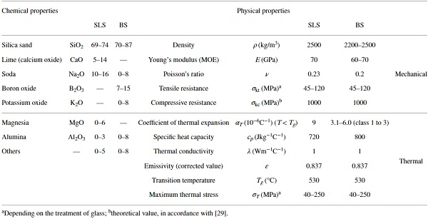
Most of glass solutions in existing or novel buildings are realized by using soda lime silica (SLS) glass. Special and limited in number applications only, when a certified level of fire resistance and heat resistance is required, are indeed realized with borosilicate (BS) glass, since offering better performance to temperature changes. BS glass applications in buildings are indeed limited, compared to huge SLS glass use for load-carrying elements, windows, etc. Table 1 reports the main chemical and physical features of SLS and BS glass types at room temperature. There, nominal values are also provided for characteristic resistances in tension and compression. As known, several SLS glass types are in fact commercially available [1, 2], with annealed (AN) float glass representing the reference base material.
The strength of AN glass is typically limited, compared to other constructional materials, with a nominal characteristic value in tension up to 45 MPa. The mechanical properties of AN glass can then be enhanced via thermal or chemical processes, leading to strengthened (HS, with 70 MPa the nominal tensile resistance value) or fully tempered (FT, with 120 MPa its tensile resistance) glasses, respectively, with improved tensile strength as well as beneficial effects especially in terms of the shape and size of shards, in the case of accidental failure, due to the initial state of residual stresses resulting from strengthening processes. For the sake of clarity, Table 1 mentions nominal values only of material mechanical properties.
Table 1. Chemical and physical properties of SLS and BS glass types (at room temperature), in accordance with [1]. - Full-size table
As far as the transition temperature Tg is not exceeded, glass behaves linear elastically under the assigned design loads. Given a combination of ordinary loads to verify, as a result, the knowledge of elastic mechanical properties and resistance values for SLS glass given in Table 1 allows then to perform analytical or FE structural analyses.
Crack occurrence and propagation, however, may even prematurely occur due to possible thermal stresses, hence requiring a typical multidisciplinary approach for such a constructional material. Thermal shocks, that is, cracking due to temperature gradient between heated and unheated glass regions, as well as due to relatively low thermal expansion coefficient of glass, are in fact typically expected to occur when the temperature gradient lies in the order of 40°C for AN glass, up to 100°C for HS glass, and 200–250°C for FT glass [1]. A huge number of research studies have been focused on thermal failure assessment of glazing windows, taking care of simple glass panels, double glass units, and point-fixed systems (Section 4).
3.2. Laminated Safety Glass and Insulated Glass
Further design issues and complexities arise as far as glass systems do not consist of single panes but are assembled in composite laminated sections and/or insulated glass units, as conventionally in use for buildings.
Laminated glass (LG) represents, in general terms, the combination of two or more glass plies together with foils consisting in a certain interlayer type. LG has been first developed for automotive applications, since early 1900, to avoid injuries in case of accidents, and only in the last decades, LG has been largely used in civil engineering applications for structural purposes. As a general rule of the LG concept, the resisting cross section is expected to respond as a composite system to external loads, hence having enhanced mechanical performances than single glass panes, both in the elastic stage and in the postcracked phase. From a mechanical point of view, the first implicit advantage of LG structural applications is that multiple glass layers can be bonded together; hence, the required level of resistance, stiffness, and redundancy can be obtained by using conventional glass thicknesses available on the market. In addition, thanks to the presence of bonding films, LG represents since decades the conventional safety glass solution in buildings, since able to hold together glass shards in case of failure, hence reducing possible risks for people (Figures 2(a) and 2(b)).
![Figure 2 Laminated glass: (a)-(b) examples of fractured LG panels and (c) variation of shear modulus for common LG interlayers (PVB and SG degradation with temperature [37]).](/sites/default/files/inline-images/Fig2_277.jpg)
Bonding films typically consist of polyvinyl butiral (PVB) films, ionoplast foils (i.e., SentryGlas® (SG)), and ethylene-vinyl acetate (EVA) compounds. As a common aspect of such possible interlayers, besides their different constitutive laws, these films are generally characterized by viscous behaviour; hence, they are generally sensitive to temperature and load-time application, as also emphasized by several research efforts [37–39]. In addition, even at room temperatures, interlayers in use for LG applications are generally characterized by relatively low shear stiffness, compared to glass (Figure 2(c)). The overall structural performance of a given LG composite section is hence highly dependent on the interlayer features, including durability and resistance.
In terms of structural design of LG systems under ordinary loads, various methods are available to account for the effects of interlayer degradation over time and temperature increase (see [1, 2] for a summary of existing formulations). As a result, at the design stage, optimal resistance and stiffness behaviours for ULS and SLS are generally ensured, as well as appropriate safety performances for the CLS postcracked stage. Mostly, null contribution, given the typical mechanical degradation of interlayers for temperatures higher than 30°C (Figure 2(c)), is however expected from interlayers under fire loading; that is, the LG section is expected to behave fully uncoupled. There, specific design assumptions should be taken into account, including the use of special intumescent compounds (Section 3.3).
Multiple glass panes (monolithic and LG sections) can then be assembled together to act as insulated glass units, both double (i.e., single gas cavity interposed between glass panels) or triple (i.e., double cavity). There, design calculations should take into account the so-called load-sharing effects due to air or gas infill in the cavities, that is, the mutual interaction between glass panes once subjected to mechanical loads [1, 2]. Ordinary climatic loads represent an additional design condition to properly verify, due to possible variations in the cavity volume and pressure. Thermal analyses of insulated glass systems are hence required even under solar exposure only. All the mentioned aspects and variables, consequently, further increase the design complexity for glazing systems under fire.
3.3. Fire-Resistant Glazing
FR glazing represents a relatively recent solution, known to provide excellent protection for lives and property in the event of fire, and hence may be used as a barrier for fire separation or compartmentation (for a specified duration), enabling occupants to assemble in a relatively safe compartment and acting as a part of an integrated “fire safety strategy” for the full building it belongs. As a crucial aspect of such solutions, FR glass systems require extreme attention in installation detailing. In addition, all the FR components, such as the glazing seals, beads, fixings, and frame, must be compatible and work together to achieve the required performance [36].
FR glazing, due also to relatively high costs, actually finds limited applications in buildings, especially where protected escapes must be ensured in the case of fire accidents. In accordance with a study carried out by Yang et al. [40], for example, FR glazing was representing in 2011 less than 5% the overall China glazing applications. Major limitations in the use of FR glass derive also from current need for additional research efforts and investigation on its actual fire performance (Section 4).
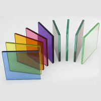
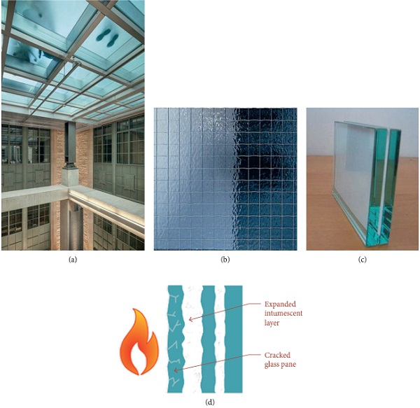
In accordance with design guidelines such as [36], FR glazing solutions actually available on the market can include (i) LG composites, obtained by bonding together different glass types (e.g., SLS glass panes with enhanced and FR glass types) with special fire interlayers (i.e., intumescent films); (ii) wired glass; (iii) ceramic glass; (iv) resin laminated glass; (v) gel laminated glass; and (vi) thermally toughened alkaline earth silicate safety glass (Figure 3). Multiple glass layers according to (i)–(vi) example types can then be combined in insulated FR glazing units. Within the given list of (i)–(vi) solutions, wired glass elements do not offer enhanced fire resistance compared to ordinary glass and typically crack early due to thermal stresses. FR performance is indeed ensured by their integral wire mesh, able to hold together and in place cracked glass pieces.
Generally speaking, for structural design purposes and mechanical calculations, a given FR system can be conventionally treated as a standard, non-FR glass element (Sections 2.1, 3.1, and 3.2), with the difference of enhanced performance under fire exposure. In general terms, FR glasses are in fact considered as effective passive fire protection (PFP) tools for buildings, with specific applications like glazed internal and external fire doors (vision panels); interior partitions and compartments; roofs, floors, and ceilings; façade panels; escape and access corridor walls; and stairways, lobbies, and enclosures (to protect shafts). Juxtaposed with PFP tools, active fire protection (AFP) systems can provide further effort in combination with PFP systems but require a certain motion and response to combat fire.
Typical AFP tools can be either automatic (i.e., water sprinklers, fire alarms, hypoxic air suppression systems, etc.) or manual (i.e., emergency evacuation, fire extinguishers, firefighters, water hoses, etc.). Fire design and optimization of such systems, however, is generally complex and requires specific competences. Combined PFP and AFP systems, moreover, are generally expected to provide enhanced benefits but could also lead to worst performances. So far, several research studies [41–45] highlighted, for example, that water films and sprinklers can provide high fire performance also to non-fire-rated, standard glass systems, as well as that FR glass curtains with water films can offer high fire performance, but limited heat resistance, or that the AFP systems can anticipate thermal shock failure in glazing windows and enclosures, leading them to premature collapse.
4. Existing Experimental Research on Glass Properties under High Temperatures
The performance of glass under high temperatures under heating and fire loading attracted the attention of several experimental research studies, since 1950s, due to the huge use of glazing panels in windows and fenestrations. Most of those investigations are related to thermal shock effects in SLS glass, as well as to its thermal characterization in general, including variations of modulus of elasticity (MOE) and resistance with high temperatures, while only limited experimental studies are currently available for composite glass systems and assemblies under fire or combined fire and mechanical loads (Section 5). Sections 4.1 and 4.2, in this regard, present a summary of major research outcomes at the material level, giving evidence of some key influencing parameters that should be properly accounted for the assessment of the fire response of structural glass systems.
4.1. Glass Transition Temperature
As a conventional nominal value for glass transition temperature, design standards suggest a conventional value Tg = 530°C (Table 1). Based on experiments carried out over last decades on SLS glass, however, standard AN glass gave evidence of high variations in Tg, with measured transition temperatures in the order of 550°C, 283°C, and 400°C [46, 47].
Rouxel and Sangleboeuf [48] measured on SLS glass specimens Tg values comprised between 450°C and 600°C, giving evidence of the thermal performance of artificially cracked specimens, including bending tests at high temperatures to monitor the MOE variations.
Due to the intrinsic properties of SLS glass, it is in fact known that, as far as the service temperature increases up to Tg, its response becomes progressively time dependent, with rapid increase of permanent deformations. Standard AN glass, based on [42–44], proved to offer a typical brittle-to-ductile (BTD) transition at high temperatures, with toughness enhancement compared to other glass types. The same BTD behaviour, however, was also observed to strongly depend on the imposed strain rate, with BTD and transition temperature increase with strain rate increase [48].
4.2. Glass Thermomechanical Properties and Temperature Effects
The elastic properties of standard glass at elevated temperatures have been extensively assessed by Rouxel [47], by accounting for experimental data available in the literature after 1950s, giving evidence of SLS glass’ MOE sensitivity to temperature, as compared with other glass types (see Figure 4, with SLS float glass labeled as “window glass”). Rather linear dependency and limited decrease can be observed for MOE values of SLS glass, as far as T does not exceed Tg, while a subsequent abrupt loss of stiffness is shown.
![Figure 4 MOE variation in SLS glass and other glass types, as a function of temperature, as reported in [47].](/sites/default/files/inline-images/Fig4_254.jpg)
Earlier experiments were also carried out both on SLS and BS glass components by Kerper and Scuderi [49], with careful attention for specimens including (i) chemically strengthened SLS glass, (ii) thermally fully tempered SLS glass, and (iii) thermally semitempered BS glass. Through the experimental study, glass laths with dimensions of 254 × 38.1 mm (6.35 mm in thickness) and 152.4 × 25.4 mm (2.54 mm in thickness) were considered. Given the (i)–(iii) specimen types and a reference temperature (0–560°C the tested range), almost stable MOE values were experimentally derived, even after sequential heating and cooling cycles. MOE values were generally found to be completely relaxed for temperatures higher than 400°C.
Close correlation can be observed with MOE variations in standard AN glass specimens, as derived from different literature sources (see Figure 5, where test results from Shen et al. [50] on monolithic SLS samples (75.43 × 14.80 mm the size, with 3.26 mm the nominal thickness) are also reported). The same Figure 5, finally, gives evidence of the typically increasing MOE values for BS specimens, as a function of increasing temperatures.
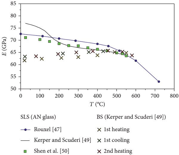
Worth of interest for structural design purposes is that Kerper and Scuderi [49] also assessed the resistance variations in SLS glass at high temperatures. In particular, no resistance losses were reported for temperatures up to 375°C (less than 5% losses, compared to room temperature), for thermally fully tempered SLS specimens. Substantial decrease of resistance was recorded only for temperatures higher than 500°C (fire exposure for several hours) and 550°C (15 minutes of fire exposure). Chemically strengthened SLS glass showed indeed a pronounced resistance degradation with the temperature increase, up to 5% loss at 204°C (500 hours of fire exposure), 5.8% at 260°C (500 hours), and 100% at 600°C (6 hours).
Following [49], a huge number of experimental studies related to SLS glass performance have been focused on thermal breakage assessment, being representative of the major cause of glass cracking for windows. The issue of glass thermal cracking and fallout has been first raised in 1980s by Emmons [51] and other researchers [52, 53], while in the last decades, an increasing number of experiments have been carried out on small-scale specimens, single glass panes, or double glass panes variably supported, under the effect of fire or heat radiation (see, e.g., [54–60]). Numerical investigations were, for example, proposed in [61–63], giving evidence of edge and boundary condition effects on the thermal response and breakage of standard window glass panes.
Malou et al. [64] carried out thermal resistance experiments on 3 mm thick, SLS, AN glass specimens (15 × 50 mm their nominal size). A rather constant value was recorded for the tensile strength of glass, up to a temperature increase of 270°C (Figure 6(a)). Higher temperatures were indeed associated to a sharp decrease in the measured resistance (more than 50% the reference value at room temperature), giving evidence of thermal shock effects and damage propagation in glass specimens, as well as of generally limited performances of AN glass. A rather smooth MOE decrease was also observed (Figure 6(a)).
![Figure 6 Thermal characterization of SLS glass. (a) Variation of MOE and resistance, under thermal shock [64], and (b) dependency of thermal shock resistance to glass thickness (in gray italic, the number of tests for each thickness), in accordance with [65].](/sites/default/files/inline-images/Fig6_221.jpg)
Later on, Xie et al. [65] experimentally investigated the tensile resistance of SLS, AN glass specimens at high temperatures. Quasi-static tensile tests were carried out on small specimens, with thickness comprised between 4 mm and 12 mm (2 mm the difference between each set of specimens). Test repetitions on specimens with the same geometrical properties were carried out at 25°C and 200°C, where the critical breakage resistance was derived as the first cracking occurrence. In Figure 6(b), evidence of such test results (average values, with minimum and maximum values for each series) is provided. In accordance with [65], a negligible decrease of resistance was noticed for specimens exposed to 200°C, compared to room temperature results, while higher sensitivity was observed especially to glass thickness (Figure 6(b)).
Worth of notice that, as far as different literature references are examined (see, e.g., [66]), even counterposed experimental findings can be derived, giving evidence of a typically high scatter and sensitivity of glass thermal resistance to elevated temperatures, hence suggesting further testing and investigations at the material level.
Moving from the material to the assembly level, such a need of further experimental assessment and investigation can be further perceived.
Experiments related to the thermal breakage of specific glazing systems under fire loading have been in fact carried out only recently, that is, for double glazing units [58] or point-fixed glazing panes belonging to curtain walls [60]. In the case of point-fixed panes, for example, a high sensitivity of thermal breakage (i.e., time of failure and crack pattern) was typically observed, based on the position of point connectors (see an example in Figure 7). The actual performance of such a kind of specimens—as expected from the examined boundary configuration—proved to be strictly related to combined thermal exposure effects as well as to mechanical loading (i.e., self-weight of point-fixed panels, leading to additional stress peaks close to the holes), hence requiring a detailed investigation of both combined aspects.
![Figure 7 Fracture of point-fixed glass panels, in accordance with [60]. (a) Connector detail; (b) experimentally observed crack opening (front view); and (c) corresponding schematic representation.](/sites/default/files/inline-images/Fig7_206.jpg)
In this regard, Chen et al. [17] studied the thermal breakage performance of standard AN windows, under the effects of combined thermal loads and wind pressures. Steel frame-supported, monolithic 0.6 × 0.6 m panels (6 mm their thickness) were subjected to a reference fire loading and various levels of wind pressures (up to 11 m/s the wind velocity on glass surface). Glass cracking, in some case, occurred together with fallout of samples from the supporting frame. Test results (15 specimens in total), however, generally proved that the first cracking time markedly decreases with increasing the imposed wind pressure; that is, mechanical loads (wind, in this specific case) can highly accelerate the failure of thermally loaded glass systems. As a result, detailed investigations inclusive of combined thermal and mechanical loads well representative of the actual loading and boundary configurations for the examined structural glazing system should be generally carried out.
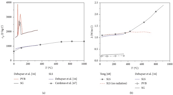
In the case of LG systems, for example, the thermal performance of interlayers of common use should be properly taken into account. In this regard, Debuyser et al. [16] investigated the behaviour of monolithic and triple-layer LG specimens composed of standard AN glass, under the effects of radiant heating. Nominal thicknesses of glass panes of 6 mm, 10 mm, and 15 mm were taken into account, being bonded together in LG sections by PVB or SG layers (0.76 mm or 1.52 mm the thickness of interlayer foils).
Low-E coated, monolithic specimens were also included in the set of experiments. Both radiant and transmittance tests were carried out, giving evidence—in accordance with earlier research efforts—of the relatively limited resistance and low thermal performance of AN glass specimens, due to the premature occurrence of thermal cracks as well as due to the poor thermal reaction of bonding interlayers (in the case of LG specimens). Critical design issues were also emphasized, by taking advantage of a 1D model able to capture the actual thermal response of the tested specimens. Thermal properties of PVB and SG foils, up to 340°C, were also reported (Figure 8). Test results collected in [16]—even limited to maximum temperatures of 340°C—generally showed a close correlation with past literature references for SLS glass [67, 68] (Figure 8). Worth of interest is also the thermal characterization of PVB and SG foils.
5. Existing Experimental Research on Glass Systems and Assemblies
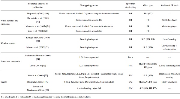
Although the relatively large number of experimental studies focused on the thermal performance of glass as a constructional material, limited literature efforts are still available on the fire performance of full glass systems and assemblies (see a selection in Table 2).
Table 2. Summary of selected experimental research studies on structural glass systems under fire. - Full-size table
5.1. Glass Walls, Facades, Enclosures, and Windows
Glazing enclosures and walls attracted the attention of researchers especially during the last years, to assess the fire performance of novel FR solutions in place of standard glass. In doing so, the actual boundary and loading configurations were properly taken into account in defining the test setup and methods, so as to reproduce the testing conditions of full-scale specimens as a part of full buildings and complex systems.
Glass enclosures designed for an extension of Washington Dulles International Airport (automated train system for passengers) were tested under fire conditions in 2007, as reported by Mejicovsky [69] (Figure 9(a)). Glass panels with 3.8 × 3.6 m high dimensions and supported by interior steel frames (4.7 m the average bay width) were investigated. Special details were defined (even using standard, non-fire-rated materials), so as to offer appropriate redundancy to the glazing system, even in the case of an accidental event. To this aim, a special mock-up was also designed, so as to simulate the actual fire-loading condition for the glazing enclosure.
![Figure 9 Glass enclosures under fire. (a) Evidence of partial delamination, as reported in [60] and (b) full-scale glazing wall tested in [70]. In evidence, it is possible to notice the loss of wall integrity and initiation of gel melting, after 49 minutes of fire exposure.](/sites/default/files/inline-images/Fig9_154.jpg)
Glass elements for overheads and walls were designed in the form of LG sections, composed of two 10 mm thick FT glass panes bonded by a 1.52 mm thick PVB interlayer. Glazing joints were then realized by means of silicone rubber setting blocks and structural silicone sealant joints (Dow Corning 995™ type), while the glazing channel and edge trims consisted of minimum 3 mm thick stainless steel. The fire test was stopped after 35 minutes of exposure, with temperatures in glass over 250°C (up to 400°C in the last 5 tests of the experiment). Postexamination of the glazing system revealed no cracking or dislodgement of components, but localized melting and off-gassing of the PVB interlayer was observed, in the form of small bubbles and/or partial delamination (see details of Figure 9(a)).
A full-scale standard fire test according to EN 1363-1 and EN 1364-1 was reported by Machalická et al. [70] for a glass wall supported by an aluminum frame. The wall (3.475 × 4.57 m the overall size) consisted of three special FR, LG panels, gel-filled type (1.4 × 4.5 m the size of the central LG panel, 1 × 4.5 m for the lateral panels). Small gaps between adjacent glass panes were filled by means of special FR tapes and sealants. Collapse of the glass wall occurred after 49 minutes of fire exposure, with maximum temperatures in the order of 150°C (Figure 9(b)).
Both double LG panels composed of special tempered glass, gel-filled type (SAFTI SuperLite II-XL™ type, with 19.05 mm the total thickness), and monolithic glass panels (6.35 mm the thickness) were assembled together to obtain the glazing wall tested in [71]. Such a glass wall (two glass panels for each cross-section type) was frame-supported and had overall dimensions of 2.42 × 2.42 m. Fire experiments gave evidence of limited fire performances of simple glass panels, compared to FR components. Monolithic glass panes in fact were characterized by premature fallout from the supporting frame (i.e., 3 minutes after ignition, with 0.8 seconds elapsing between the occurrence of first cracks in glass and the final fallout of monolithic panes (Figure 10(a))). Double LG panels, in contrary, remained intact up to test conclusion (>30 minutes), without visible cracks or failure mechanisms close to connections with the framing system.
![Figure 10 Failure mechanism in FR glass systems, as observed by (a) Manzello et al. [71], with evidence of fallout, and (b)-(c) by Yang et al. [40] on FR monolithic panes.](/sites/default/files/inline-images/Fig10_130.jpg)
This is not the case of experimental studies carried out by Yang et al. [40] that tested monolithic, FR glass panels under standard fire curves. The experimental study gave in fact evidence of major issues deriving from framing systems and related connections. Even the FR glass panels proved to offer high performances under fire loading; in particular, loss of integrity was observed to have origin in the glass-to-metal frame connection detailing (Figures 10(b) and 10(c)). Further fire experiments and numerical investigations on glass facade systems can also be found in [78–82], with evidence of the performance of specific glass system typologies, including cable-net systems and inclined facades.
5.2. Retrofitting and Enhancement of Standard Glass Windows
Several types of protective films able to improve the fire performance of existing and novel standard windows are available on the market. Although these coatings do not affect the room temperature elastic stiffness and resistance of a given glass pane to retrofit, the same films can be beneficial in delaying high-temperature effects, hence resulting in increased FR performance.
Koudijs and Csoke [72] first gave experimental evidence of the high potential of protective films for traditional glass systems, with careful consideration for the improved fire performance of windows composed of SLS glass, by taking into account a case study building in Rotterdam (NL) (Figure 11(a)). Low-E coatings were interposed within traditional double glazed units, by assessing the effects of their position (i.e., interior cavity face, etc.) under fire loading. The integrity of window samples was ensured for 27 minutes in the case of AN glass but increased up to 60 minutes in presence of HS glass panels, hence giving evidence of the potential fire performances of traditional insulating systems inclusive of special coatings.
![Figure 11 Experiments on coated glazing windows, as reported in (a) [72] and (b) [73], schematic cross-sectional view.](/sites/default/files/inline-images/Fig11_118.jpg)
Misawa et al. [73] also tested the efficacy of special refractory films, basically intended for application on the interior side of existing standard windows. The typical specimen consisted in a double glazed unit, Low-E coated, with 1 × 1 m the reference size. There, a novel refractory film was attached to the interior face of the glazed unit (i.e., on the glass surface expected to be exposed to fire). The refractory film consisted of (i) an external polyEthylene terephthalate (PET) film bonded to (ii) an ultraviolet protection layer and (iii) a silicate soda-based material layer (1 mm its thickness) (Figure 11(b)). 12 tests were carried out in total, including variations in AN glass supplier, thickness (8 mm or 12 mm), and specimen size (30 × 30 cm, 100 × 100 cm, and 94 × 94 cm) as well as Low-E film surface of application and comparisons with clear uncoated specimens. All the experiments proved the high efficiency of refractory films, allowing Low-E double glazing units to achieve minimum 20 or 30 minutes of fire performance, as required for FR windows.
Although the mentioned research studies generally proved the potential and efficiency of such special coatings to enhance the FR of glazing systems, several aspects should be still assessed. Wu et al. [83], for example, experimentally investigated the high-temperature performance and thermal degradation of protective layers of common use for glass applications, giving evidence of gas emissions when exposed to fire.
5.3. Glass Floors and Overheads
Siebert and Maniatis [74] reported on fire tests carried out on glazing floors belonging to the subway station “Olympiapark Nord” in Munich (Germany). In the ceiling tunnel, overhead glazing accessible to person steps was made accessible by means of several openings (5 × 3.5 m the size). FR requirements were taken into account, as a possible configuration deriving from accidents (i.e., trains burning in the tunnel). Special multilayered safety LG panels were designed and tested under fire, in order to ensure appropriate safety levels (Figure 12). No test results and fire-performance-related data are available in the literature, however.
![Figure 12 Fire tests on glazing floor, as reported in [74]. (a) Initial state and (b) failure pattern (detail).](/sites/default/files/inline-images/Fig12_103.jpg)
Similar fire experiments are summarized also in [75], referring to the glazing floor panels designed, in 2011, to be installed at a height of 130 m in the historic Blackpool Tower (UK), as a part of an ongoing refurbishment project. A full-scale fire test was carried out (Figure 13), with 4.42 × 3.8 m the overall size of the flooring system. The mild steel-treated frame and related gaskets were also included within the test setup, so as to assess the fire performance of the full glazing system under its actual restraint configuration.
![Figure 13 Fire tests on glazing floor, as reported in [75]. (a) Setup overview and (b) detail of the ongoing fire test.](/sites/default/files/inline-images/Fig13_93.jpg)
Aiming to ensure appropriate structural integrity as well as overall performances in the case of fire accidents, the typical glass panel (3 × 1.1 m the maximum size) consisted of a LG section, three 10 mm thick, FT glass layers, bonded together to a 23 mm Pilkington Pyrostop™, by using a special liquid composite bonding (Koediguard™ type). Steel-framing elements were also preliminary treated with intumescent coatings, mineral wool, and fire check boards. Additional expansion joints were finally included in the setup, in order to prevent buckling in the supporting frame members. The fire experiment was carried out in accordance with EN regulations, assigning to the flooring system a standard fire curve and a simultaneous mechanical load, being representative of crowd (5 kN/m2, distributed uniform pressure or 4.5 kN point load (50 × 50 mm foot print), resp.).
The fire performance exceeded 60 minutes of integrity (test stopped after 68 minutes), with maximum recorded temperatures of 67.6°C and no evidence of debonding or failure. Compared to fire insulation requirements (EN 1363-1), where temperature rise should not exceed 140°C (Section 2), a tolerance of > 120°C was hence ensured (12°C the ambient temperature during the test). Posttest deflection of 16.5 mm was measured (with 1/175 the roof span deflection limit value provided by standards).
5.4. Glass Beams
Limited experimental literature background can be found for structural glass elements under fire loading, due to the relatively recent demand of vulnerability assessment and protection for these systems.
Veer et al. reported in [22] on a set of bending test comparative results, experimentally obtained from monolithic and LG beams under fire, to assess the effects of intumescent coatings. The fire loading was imposed in the form of a constant flame at 650°C, with a fixed distance from the beams’ lateral surface (Figure 14). Various beam geometries (40 mm × 400 mm the overall size) were tested, including specimens with different thickness and standard SLS glass types, such as
(a) 6 mm thick, AN glass;
(b) 6 mm thick, chemically toughened glass (120 MPa the initial stress);
(c) 3 mm thick, chemically toughened glass, laminated with 1 mm polycarbonate (PC) foil (3 glass layers + 2 PC films);
(d) 3 mm thick, segmented, chemically toughened glass, laminated with 1 mm PC foil (3 glass layers + 2 PC films). Compared to C, glass layers were bonded to PC foils in an overlapping pattern;
(e) An LG beam (as in the case of C and D type specimens), including insulating cavities on the external sides.
![Figure 14 Summary of fire experiments carried out in [22]. (a) Four-point bending setup (in evidence, the foam layer provided by intumescent paint (specimens A)), (b) cross-section features of specimens E, and (c) buckling of segmented beams (type D).](/sites/default/files/inline-images/Fig14_81.jpg)
All the (a)–(e) configurations were tested both without and after the application of intumescent coating (FlameGuard HCA-TR™ paint type).
A conventional four-point bending test setup was used for these beams. Experiments with no external mechanical loading as well as with additional weights (with up to 24 MPa the corresponding midspan bending stress) were carried out on monolithic AN specimens (type A) (Table 3).
Table 3. Summary of bending test results reported in [22]. - Full-size table
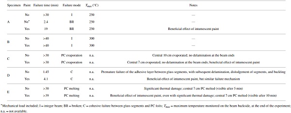
The overall experimental investigation gave evidence of some important aspects, as, for example, the potential safety level of structural glass beams under fire.
However, critical aspects were also emphasized for the same specimens, like, for example, in the case of segmented beams (type D, see Figure 14(c)). Some preliminary FE simulations were also reported in [22], giving evidence of the temperature distribution and related stress effects for the examined beams. Worth of interest is in fact that such preliminary FE models gave evidence of temperature peaks in the adhesive layers providing structural bonding between the glass segments, hence emphasizing the crucial role of detailing.
Bokel et al. [76] later explored similar glass beam specimens, by taking into account the same overall geometrical features and test setup presented in [22]. The novel aspect was represented by testing LG beams composed of special FR glass (i.e., Pyroguard™ type as well as LG beams composed of 3 SLS glass layers, with epoxy films acting as interlayers for all the specimens). As a general outcome of the experimental investigation, epoxy layers were found to start charring after few seconds only, with limited fire performance of the beam specimens. An almost comparable behaviour was observed for all the beams, both composed of special Pyroguard layers or not, hence giving evidence (besides the limited number of tests) of the need for further extended investigations.
Louter and Nussbaumer [77] performed full-scale experimental tests on LG beams composed of standard glass layers. Differing from [18], a standard fire curve was considered for loading onto the oven, in accordance with EN regulations (Section 2). Through the experimental study, 3 full-scale beams were investigated. Given the same overall dimension of beams (1 m × 0.1 m), variations were accounted in terms of glass type (AN, HS, and FT, resp.). The reference cross section consisted of 3 SLS layers, 10 mm in thickness, bonded together by SG foils (1.52 mm in thickness).
A four-point bending test setup was considered, with end supports protected from fire exposure, and the fire loading was assigned together with a simultaneous, constant mechanical load taking the form of 115 kg at the midspan section. Given the limited stress effect due to the assigned mechanical load (with maximum tensile stresses in the order of 5 MPa at beams’ midspan), the specimens proved to offer a rather stable behaviour under fire, for >40, >45, and >50 minutes in the case of AN, HS, and FT beams, respectively, up to collapse (Figure 15). As a general observation from such a kind of tests, the interlayer foils started melting and leaking off from their position after few minutes of fire exposure only; hence, the SLS glass panes behaved as almost fully uncoupled layers. On the other hand, protecting the beam ends from fire allowed to avoid premature collapse mechanisms.
![Figure 15 LG glass beams tested by Louter and Nussbaumer [77]. Typical failure configuration.](/sites/default/files/inline-images/Fig15_63.jpg)
6. Summary and Conclusions
In this paper, a state of art on structural glass systems under fire loading was presented, with careful consideration for current design methods and issues as well as experimental research efforts. Besides the continuously increasing use of glass in buildings as a constructional material able to interact with and/or replace materials of traditional use, the actual behaviour of structural glass assemblies, in general, currently requires further investigations, as well as the application of specific fail-safe design rules. This is the case of glazing systems under ordinary loads, but especially of extreme loading conditions, as, for example, fire accidents.
As shown, the intrinsic features of glass and its interaction with other components (i.e., framing systems, boundary details, etc.) make glazing systems highly vulnerable to temperature variations, as well as combined effects of thermal and mechanical loads, hence requiring multidisciplinary approaches in their design. In doing so, appropriate structural safety levels should be in fact ensured in combination with multiple aspects, such as transparency, aesthetics, and lightening requirements.
At the material level, in particular, a wide set of experimental research can be found in the literature, aiming to assess major effects of high temperatures on MOE, tensile resistance, and thermal cracking of standard glass. Most of these experimental outcomes are in rather close agreement as far as the MOE variation with temperature is considered. But when different literature sources are accounted, however, test results can also give evidence of high scatter in the observed trends, as, for example, in the case of glass thermal resistance (Section 4). In addition, while most of glass applications in building consist of laminated or insulated glass systems, few experimental studies only are actually available to characterize the thermal effects in interlayer foils at high temperature.
As far as the attention moves from the material to the system and assembly levels, a relatively wide set of experimental investigations can also be found in the literature, with careful consideration for the fire performance of various typologies of glass systems inclusive of a multitude of boundary configurations, fire exposure patterns, and glass types (standard and/or FR glass). As a common aspect of such experimental investigations (Section 5), connection details and restraints generally proved to have a key role in the overall observed responses, both for frame-supported and point-supported systems. Generally speaking, glass enclosures, walls, and beams proved—in most of the cases—to offer rather stable performances under fire loading, even composed of standard glass only, but requiring further extensive testing and assessment with special care for supporting details.
Finally, literature efforts have been spent in the last years also to assess the potential and efficacy of special coatings and films for the retrofitting and protection of existing glass windows and systems in general. In accordance with earlier observations, such solutions generally gave evidence of major benefits for uncoated glass specimens, but careful consideration should be still spent to properly optimize their potential.
Conflicts of Interest
The author declares that there are no conflicts of interest.
Acknowledgments
This research study has been carried out within the “Structural Task” activities of the ongoing EU COST Action TU1403 “Adaptive Facades Network” (www.tu1403.eu). In this regard, COST is gratefully acknowledged for facilitating scientific network and collaboration between the author and the Action international experts.