Article Information
- Digital Object Identifier (DOI): 10.47982/cgc.8.443
- This article is part of the Challenging Glass Conference Proceedings, Volume 8, 2022, Belis, Bos & Louter (Eds.)
- Published by Challenging Glass, on behalf of the author(s), at Stichting OpenAccess Platforms
- This article is licensed under a Creative Commons Attribution 4.0 International License (CC BY 4.0)
- Copyright © 2022 with the author(s)
Authors:
- Isabell Schulz - Institute of Structural Mechanics and Design, Technische Universität Darmstadt
- Cenk Kocer - The University of Sydney, School of Physics
- Franz Paschke - Institute of Structural Mechanics and Design, Technische Universität Darmstadt
- Jens Schneider - Institute of Structural Mechanics and Design, Technische Universität Darmstadt

Abstract
The Vacuum Insulated Glazing is a highly thermally insulating structure consisting of two (or more) glass sheets, separated by an evacuated gap, and sealed hermetically at the glass edges. An array of support pillars maintains the separation of the panes under the constant load of atmospheric pressure. The performance and durability of the VIG, in terms of thermal loads and atmospheric pressure, has been well studied and ISO Standards have recently been published (ISO 19916-1:2018 and 19916-3:2021). However, the mechanical performance of the VIG, especially when exposed to dynamic loads, has not been dealt with in the scientific literature.
The goal of this work is to investigate the mechanical performance of VIG’s subjected to soft body impact and gain insight into the failure mechanisms of the VIG when exposed to dynamic loads. Measurements of the surface stress on the glass were per-formed, when the VIG is subjected to the twin-tire pendulum impact test, as outlined in the Standard DIN EN 12600:2002. Two VIG units and one laminated VIG unit were tested and the results were com-pared to numerical data of a monolithic glass pane. It was found that the VIG failed at drop heights much lower than that prescribed in the Standard. An examination of the glass fracture patterns high-lighted an origin of fracture caused by the contact of pillar-to-glass.
1.Introduction
It is well accepted that the uncontrolled loss of energy through the envelope of a building dominates the overall use of energy in buildings (Grynning et al. 2013). Of all the components in a building’s en-velope, the single glass pane used in windows, doors, skylights, and the like, is the worst performing component (Grynning et al. 2013). For over 50 years, in extreme climates, Insulating Glass Units (IGU) have been used to improve building energy performance, and user comfort. Nevertheless, the reliance on the low thermal conductivity of the gas between the glass panes, which means thermal perfor-mance is dependent on gap size, places limits on the achievable thermal resistance and results in thick, heavy products, high installation costs, and limited window frame choice.
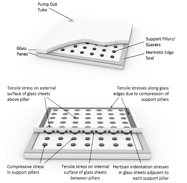
Most of the issues surround-ing the existing IGU products is overcome by the next-generation technology, the Vacuum Insulating Glazing (VIG). This technology was invented at the University of Sydney in 1991 and was commercial-ized by Nippon sheet Glass, Japan, in 1996 already (Simko & Collins 2014). The VIG, as illustrated in figure 1a, is constructed from two panes of glass, separated by a gap that is evacuated to a low pressure of 0.001 Torr or less, and typically, the gap is 0.1 to 0.3 mm (Collins and Robinson 1991). Moreover, to maintain strict control of the vacuum pressure in VIG products, the edge seal of the glass panes must be hermetic, and therefore, exhibit no permeation of gas from the environment.
VIG commercial prod-ucts are available and have a centre-of-glazing, air-to-air, thermal conductance between 1.0 and 0.4 W m-2 K-1. Once evacuated the VIG is subjected to a continuous external force because of atmos-pheric pressure. The gap distance between the glass panes is maintained by placing a regular array of submillimeter sized spacers (also known as pillars) between the panes (Collins and Fischer-Cripps 1991). Over areas of unsupported glass, the surface load produces bending stresses in the glass; figure 1bhighlights areas that are stressed. At the pillars there are contact stresses on the glass surface, includ-ing the compressive stress through the pillars (Fischer-Cripps et al. 1995; Riedel et al. 2022).
For the VIG technology to be widely adopted in transparent façades, and window systems, the me-chanical performance of the VIG must be well understood. For well-established glass products, such as monolithic panes, laminated and multi-pane IGUs, the strength limit and failure mechanisms are well known and design methods are embedded in international building codes and Standards (e.g. DIN EN 16612:2019; DIN EN 1279:2018; ASTM C1172-19; ASTM E2190-19).
For VIGs, however, Standards and building codes are currently in development. For the VIG products only ISO 19916-1:2018 and ISO 19916-3:2021 have been published; only the latter Standard outlines performance with respect to thermal loading. There are other works in the scientific literature that report on pillar contact mechan-ics (Mouginot and Maugis 1985; Fischer-Cripps et al. 1995), wind loads on units (Liu and Bao 2013), and thermal load tests (Aronen and Kocer 2017). Nevertheless, to the best of the authors’ knowledge there are no published works which report soft body impact data, which can be a critical load on glazing units.
The structure of the VIG is unique. As mentioned, unlike other single, and multi-pane, product designs, the VIG is continuously under the action of atmospheric pressure, which is about 10,000 kg/m2. In addition, it is a composite structure, where the two glass panes are directly coupled through the con-tact of the pillar array and atmospheric forces. In general, with the VIG held in a frame, which con-strains the edge of glass, most, if not all, external load configurations (e.g. surface or point loads) pro-duce spherical plate bending. The overall stress produced from bending is additive to the pre-stress from atmospheric pressure.
This implies that the strength of the VIG is not only limited by the bending strength of the underlying glass panes. The shear coupling through the pillar array produces local lat-eral and transverse contact forces at each pillar, the magnitudes of which should depend on the loca-tion of the pillar on the glass surface (Kocer 2005). Considering the size of these pillars, typically cylin-drical in geometry and about 0.5 mm in diameter and 0.2 mm in height, the contact stresses at pillars could be substantial.
For example, an impact event on the glass surface would result in high dynamic forces on pillars, which in turn would produce high local tensile stresses on the glass surface. Existing indentation, and fracture mechanics, theories suggest that the local tensile stresses on the glass sur-face could exceed 100’s of MPa (Mouginot and Maugis 1985). When considering an impact scenario, however, the failure processes are far too complex to simply determine the VIG performance through calculations.
It is the aim of this paper to present the preliminary outcome of a study on the impact resistance of the VIG. Commercial VIG units were subjected to the Standard twin-tire impact setup to study themechanical strength of the VIG and the failure processes. In the following sections the measurement setup and processes are outlined. Following this the results of the impact tests are presented.
2.Soft body impact measurements
2.1. Measurement setup and execution
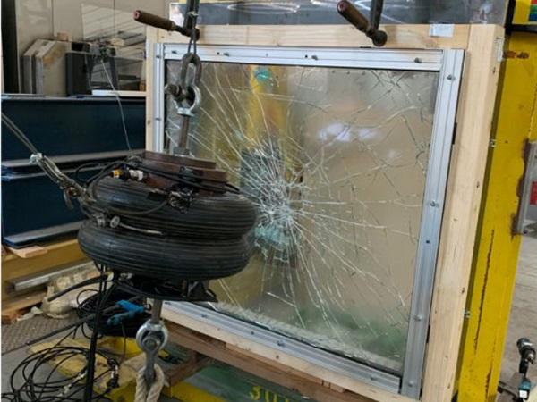
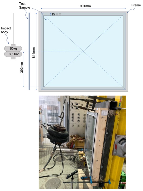
The measurements were performed following the procedure outlined in DIN EN 12600:2002. A 50 kg twin-tire pendulum body was used, where the tire pressure was set at 3.5 bar. As the available VIG units were not the size of 876 x 1938mm required in the Standard, the units were built into a typical mullion-transom frame, which was supported by a wooden frame. This was then installed onto a steel sub-structure ensuring sufficient stiffness of the framing structure. A sketch, and photograph, of the setup is given in figure 2. In order to prevent critical peak stresses at the support zones typical window-to-frame seals were used.
2.2. Measurement devices
The impact event was monitored using several measurement devices to obtain data on, 1. the surface stresses produced on the glass and 2. the acceleration of the impact body over the impact event. Tri-directional strain gauges (SG) (FRAB-2 -8 by Tokyo Measuring Instruments Lab.) were installed at the centre of the specimens, on the surface opposite to the contact surface of the impact body, i.e. on the surface where tensile stress is produced because of the overall bending of the specimen. This surface is also referred to as Surface 4 in the following. Opposite to that the surface facing the impactor will be addressed as Surface 1. The inner surfaces are Surface 2 and 3 (see Table 1). The position of the SG relative to the pillar array of the VIG units is illustrated in Table 1. The measured strains were used tocalculate the principal stresses using the following equation (Hoffmann 1987),
![]()
where E is the Young’s modulus of glass (70 000 MPa according to DIN EN 16612:2019), n the Poisson’s ratio of glass (0.23 according to DIN EN 16612:2019) and e0°,45°,90° are the measured strains from the SG. The acceleration sensors (PCB-(M)622B01 by PCB Piezotronics, measurement range ±50g) wereinstalled on the pendulum body (above and below the twin-t ires parallel, and in-line, with the direction of acceleration). The measurement frequency was set to 10 000 Hz, to ensure sufficient transient res-olution of the impact event. All the SG and acceleration sensor outputs were collected, amplified and logged using the HBM QuantumX MX840A.
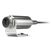
All measurements were performed at an ambient temperature of about 20 °C and a relative humidity of about 20 - 40 %. For the VIG specimens, before and after each impact, the pillars close to the impact contact area, as well as other specific areas over a line from the specimen centre to edge, and near a corner, were observed using a microscope camera. Magnified images of these pillars, and the glass area around the pillars, provides insight into the fracture caused by pillar-to-glass contact during the impact event.
2.3. Test specimens
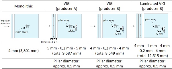
Four different glass units were impact tested. First, reference tests were conducted on monolithic 4mm thick glass panes. The results were compared to the results of an existing Finite Element (FE) impact model using SJ Mepla. The configuration of the simulated configuration is described in the following results section. Second, the VIGs of two commercial producers were impact tested. Both products use annealed glass, metal pillars and a rigid edge seal. They differ in glass thickness and the pattern of the pillar array. One of the VIG units from producer B was laminated. For lamination a method was chosen which uses cast resin. In comparison to other lamination techniques (e.g. Autoclave or vacuum bag) this process does not use high pressure, or high temperatures, to create bonding between the glass and interlayer. In effect, the VIG structure is laminated with great care.
An overview of the test speci-mens, and the configuration of each, is presented in Table 1. The nominal thickness of the components, as specified by the producer, as well as the average total thickness measured using a digital caliper, are shown in Table 1. All test specimens were of the size 814 (H) x 901 (W) mm and before testing were covered with a thin self-adhesive plastic foil (a foil typically used as a book binding film (bits&paper GmbH)) which does not add to the stiffness of the underlying glass panes or affect the measurements undesirably. The surface foil prevents the glass from falling out once broken, which protects the twin-tires from glass splinters and preserves the fracture pattern of the glass. The photographs presented in the results section were taken directly after the impact event.
Table 1: Overview of the test specimens and information on thickness, array spacing, glass surface and strain gauge position
2.4. Choice of drop height
According to DIN EN 12600:2002 and DIN 18008-4 (2013) drop heights of 450 mm, 900 mm and 1200 mm should be tested. Since we do not have any data to predict the strength of the glass, and it is reasonable to assume the samples may be much more vulnerable to impact failure, lower drop heights were chosen to cautiously approach the critical drop height for glass failure. The first VIG (pro-ducer A) was impacted from a drop height of 100 mm, which resulted in catastrophic failure. Therefore, for the subsequent impact tests the initial drop height was set to a much lower 20 mm, and if the sample did not break the second impact height was set to 50 mm. It was found that all samples failed at 50 mm or less, and thus, higher impact heights were not tested.
3.Results and Discussion
3.1. Reference measurements of 4mm monolithic units and FE simulations
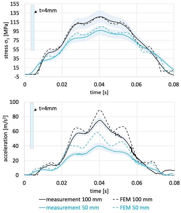
In figure 3 the plots of theσ1 stress, and acceleration, on a 3,801 mm thick monolithic pane are shown, for impact drop heights of 50 and 100mm. With these data the FE simulation results are also given for comparison. A simply-supported edge of glass boundary condition was used in the simulation. The measured and FE data in Figure 3 are in good agreement, which implies that the measurement setup is well represented as a simply supported boundary condition. The differences between the measured and FE data are due to several issues, 1. the error in setting the drop height, which is much larger for low impact heights, 2. the measurement error associated with the sensors, and 3. limitations in the underlying FE theory to account for the full dynamic effects.
3.2. VIG (producer A), drop height 100 mm
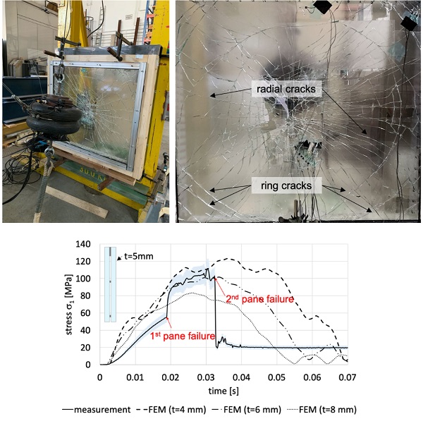
It is worthwhile to consider the impact test of the VIG (producer A) at the 100 mm drop height. Both the glass panes of this VIG unit failed catastrophically when impacted at 100 mm. Two fundamentalfracture processes were observed on the glass panes (see figure 4). First, in both glass panes radial cracks originating in the impact contact region (centre-of-glass) formed. The impact energy was high enough so that pieces of broken glass were ejected from the centre-of-glass area despite the thin plas-tic foil covering the glass surface. Over the glass pane facing the impactor, additional concentric circular cracks (ring cracks), axially centered to the centre-of-glass, were formed.
These fracture patterns are consistent with the centre impact and progressive bending of the sample. At the impact point, bending creates compressive stress on the glass under the impactor (Surfaces 1 and 3), and tensile stresses over the glass surface on the opposite surfaces (Surfaces 2 and 4). As the bending continues, the stresses in the glass at the edge of the frame increase such that there are tensile stresses produced on Surfaces 1 and 3, closer to the edge of the sample. It is from these edge tensile stresses that the ring cracks, as shown in figure 4, originate.
This was reported by Chiu (2015) for VIGs under a ball drop impact test and matches stress plots of monolithic panes simulated in SJ Mepla. Figure 5 is a plot of the s1 stress on Surface 4. From the stress result one can see that glass failure progressed in two steps. About 17ms after initial impact the first pane broke leading to a sudden increase in the stress and 15ms later the second pane broke, being the one on which the strain gauge was applied.
3.3. VIG (producer B), drop height of 20 and 50 mm
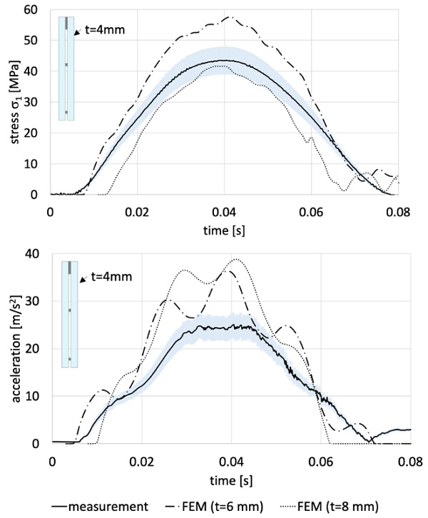
Figure 6 are plots of the measured 1st principal stress (s1) and acceleration for a VIG impacted at a drop height of 20 mm, where the VIG survived the impact event. The FE results for impact on an 8 and 6 mm monolithic glass panes are also given. The VIG is constructed from 4 mm glass, and thus, would be an equivalent total thickness of about 8 mm. However, it is interesting that, in Figure 6, overall, the VIG response does not match that of a monolithic glass pane. Even though there is some correlation be-tween the magnitude of s1, the period of the data does not agree. The similar is observable for the acceleration data, yet here not even the magnitude is in agreement. In addition, the acceleration data seems to indicate that the vibrational modes of the VIG show quite a different behavior to the one observed for the monolithic glass panes.
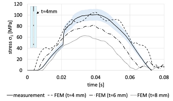
For the second impact, the drop height was increased to 50 mm, and at this height the glass pane on the impactor side failed. The failure origin was at the position of a pillar near the centre of the unit. The failure process is addressed in the section concerning the laminated VIG, since the same failure was observed for both specimens. From the s1 stress data in figure 7, the second pane did not fail during the impact event, where the data clearly indicates that the stiffness decreases; i.e., the tensile stress increase caused by failure of one of the panes is observable.
3.4. Laminated VIG (producer B)
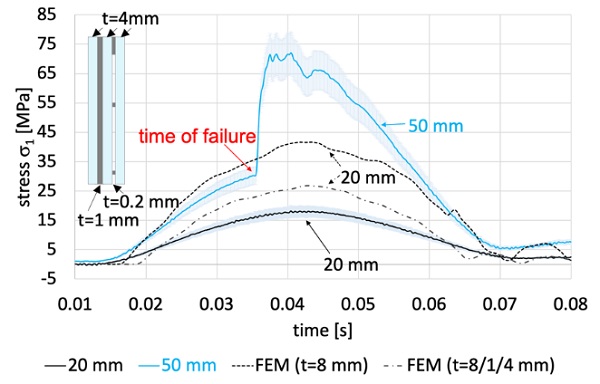
Figure 8 is a plot of the s1 stress of the laminated VIG. When comparing the stress data, for 20mm drop height in figure 8 to the data in figure 6, it is clear that the maximum measured stress is lower for the laminated VIG because of the increased stiffness of the additional glass pane. However, at the 50 mm drop height, the stress measured on the laminated VIG, when the single glass pane failed, is lower than that measured in the VIG only. This is an indication that the failure of the glass may not be due to the tensile stress from the overall bending of the sample.
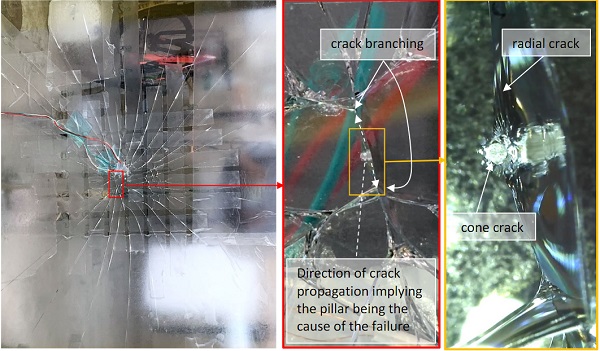
To gain further insight, the failure pattern in the glass was examined in detail. By correlating the branching events at the cracks it was found that theorigin of failure was at a pillar contact point. Images of the fracture pattern are shown in Figure 9, with a magnified image of the pillar at the origin of failure. The fracture pattern at the pillar is indicative of an indentation process, where a contact “cone crack” has formed because of the high tensile stresses on the glass surface. What is unique, however, is that the cone crack in this case has formed into a larger asymmetric geometry which has then propagated into a radial crack.
This is possible since at the failure point the local contact load on the pillar forms the cone crack, which extends into the glass as the impact event progresses. Once the cone crack extends far enough into the glass to be influenced by the stress field due to bending of the glass panes, it propagates in two directions away from the pillar following the radial stress trajectory (see figure 9b) . Since the crack at this stage is ‘accelerating’ it is highly likely ‘branching’ (also known as bifurcation of the crack front) will occur (Hull 1996). This is clearly seen as the two branching fracture lines that originate at the pillar. When the other failed VIG samples were examined the same failure origin at a pillar was identified.
The pillars surrounding the fracture origin within the contact location of the impactor were also in-spected using a microscope camera with a x200 magnification. Asymmetric cone cracks at these pillars were found which imply that strong shear forces acted on the pillars during the impact event. When the VIG is placed into bending during the impact event, the glass surfaces facing the vacuum gap will move relative to one another (Surfaces 2 and 3). This means that the pillars on the glass surface will feel a shear force, which is equal and opposite on either side of the pillar contact (Kocer 2005).
The shear forces on the pillar will produce high tensile surface stresses on the trailing edge, and high com-pressive surface stresses on the leading edge, of the pillar, in the direction of the shear load. Similar cone crack patterns were observed in all the other tested VIG products. The size of the cone cracks, and the number of affected pillars, were especially high in regions near the impact contact zone. The overall damage at pillars in the VIG tested at a drop height of 100 mm was much higher than that observed in the VIGs tested at a drop height of 20 and 50 mm. What is noteworthy is that damage at the pillars was also found at the initial drop height of 20 mm. It is reasonable that the initial damage observed would have continued to grow when the units were tested at 50 mm.
This does raise the question of whether or not the procedure of soft body impact is applicable to VIGs. It would be much more appropriate if the impact test procedure required the local damage at pillars to be identified and recorded. Which in turn raises the question: Is it reasonable to suggest that if fracture of the glass at a pillar is observed then the VIG unit is deemed to have failed the impact test?
4.Conclusion and Outlook
This paper presents the first insights into the mechanical behavior of Vacuum Insulated Glazing (VIG), when subjected to a soft body impact. The VIG is a structure that is pre-stressed because of atmos-pheric pressure, which produces concentrated contact stresses at the pillar-glass surface. During an impact event the contact surface stress field and the overall bending stress field are additive. This re-sults in a fracture process where the highly tensile contact stresses produce cone cracks that propagate and are the catalyst for the larger radial cracks which cause catastrophic failure of the glass panes.
This fracture process is quite unique to the VIG structure, and more importantly, the VIG units tested in this work are significantly weaker in strength than the underlying glass from which they were produced. In the Standards, DIN EN 12600:2002 and DIN 18008-4 (2013), the minimum test drop height is 450mm, which suggests that the VIG units tested would not be considered strong and safe in a building façade.
This work presents the preliminary outcomes of an ongoing study at the Technical University of Darm-stadt. The main goal of the investigation is to gain a deeper understanding of the physical processesof the VIG structure subjected to mechanical loads , find potentials for optimization and integrate the knowledge into proper design concepts. In the next phase of the work, more measurements will be performed on other VIG designs, e.g. differing the glass thickness, glass type (annealed vs. tempered), pillar properties, and glass size. In particular, in parallel with the measurements, numerical simulations, employing the finite element method, are underway to gain greater insight into the fracture processes. Using the simulations, a much larger range of parameters can be explored; including, but not limited to, effects of edge framing, pillar properties, surface contact dynamics, and glass size and thickness.
Acknowledgements
We gratefully acknowledge financial support from the German Federal Ministry for Economic Affairs and Energy [grant number 03EGB0021B]. We also want to thank H.B. Fuller / Kömmerling for laminat-ing the VIG unit using a temperature and pressure independent technique.
References
Aronen A., Kocer C. Vacuum insulated glazing under the influence of a thermal load. In: All Eyes On Glass, Glass Processing Days, Finland, Glass Processing Days, Glaston, Finland, vol GPD2017, pp 273–279, (2017)
ASTM E2190-19 Standard specification for insulating glass unit performance and evaluation. Standard, American Society for Testing and Materials (2019)
ASTM C1172-19 (2019) Specification for laminated architectural flat glass. Standard, American Society for Testing and Materials
bits&paper GmbH. Buchschutzfolie. HERMA - Fachshop. https://www.herma-fachshop.de/Buchschutzfolie-kg390.aspx. Accessed 26 April 2022
Chiu, A. Mechanical behavior of vacuum insulated glazing. Master thesis (unpublished), University of Sydney, School of Physics, Supervisor: Dr. Cenk Kocer. (2015)
Collins, R. E.; Fischer-Cripps, A. C. Design of support pillar arrays in flat evacuated windows in: Australian Journal of Physics, 44(5), pp. 545–564. (1991)
Collins R. E., Robinson S. Evacuated glazing. Solar Energy47(1):27–38. (1991)
DIN EN 12600. Glass in building-pendulum test-impact test method and classification for flat glass. German version EN 12600:2002
DIN EN 16612. Glass in building – Determination of the lateral load resistance of glass panes by calculation; German version EN 16612:2019
DIN EN 1279. Glass in Building – Insulating glass units – Part 1-6; German version EN 1279:2018
DIN 18008-4. Glass in Building – Design and construction rules – Part 4: Additional requirements for barrier glazing (2013)
Fischer-Cripps, A. C.; Collins, R. E.; Turner, G.; Bezzel, E. Stresses and fracture probability in evacuated glazing in: Building and environment 30(1): pp. 41–59. (1995)
Grynning, Steinar, et al., Windows in the buildings of tomorrow: Energy losers or energy gainers? Energy and buildings, 61: pp.185-192. (2013)
Hoffmann, K. Eine Einführung in die Technik des Messens mi. Hottinger Baldw, 1987.
Hull, D. Influence of stress intensity and crack speed on fracture surface topography: mirror to mist to macroscopic bifurca-tion. Journal of materials science, 31(17), 4483-4492. (1996).
ISO 19916-1. International Organisation for Standardization, Glass in building ‒ Vacuum Insulating Glass - Part 1: Basic Specification of Products and Evaluation Methods for Thermal and Sound Insulating Performance. (2018)
ISO 19916-1 International Organisation for Standardization, Glass in building ‒ Vacuum Insulating Glass - Part 3: Test meth-ods for evaluation of performance under temperature differences. (2018)
Kocer, C. Ball drop impact on Vacuum Insulated Glass; a finite element analysis, University of Sydney, School of Physics, In-ternal Report, (2005)
Liu XG, Bao YW Theoretical and experimental studies on strength and stiffness of vacuum glazing. In: Key Engineering Mate-rials, Trans Tech Publ, Vol 544, pp 265–27. (2013)
Mouginot, R., and Maugis, D. "Fracture indentation beneath flat and spherical punches."Journal of materials sci-ence 20.12 :4354-4376. (1985)
Riedel, H., Mokdad, S., Schulz, I., Kocer, C., Rosendahl, P.L., Schneider, J., Kraus, M.A. and Drass, M. Automated quality con-trol of vacuum insulated glazing by convolutional neural network image classification. Automation in Construction 135 (2022): 104144.
Simko, T., & Collins, R. E. Vacuum glazing: Development, design challenges and commercialization, Australian Journal of Mechanical Engineering, 12(3), 305-316. (2014).
Turner G, Collins R, Fischer-Cripps A, Tang J. Limits to performance of evacuated glazing. In: Optical Materials Technology for Energy Efficiency and Solar Energy Conversion XIII, International Society for Optics and Photonics, vol 2255, pp 648–659. (1994)