Authors: Alina Joachim, Jan Wünsch & Bernhard Weller
Source: Glass Structures & Engineering volume 6, https://doi.org/10.1007/s40940-020-00142-6
Abstract
The trend in modern architecture towards high-quality building envelopes is continuing. Due to its high surface quality and the broad colour spectrum, enamelled glass is used for weather protection and as a design element. The novel elements discussed in this paper do not require any sealant or adhesive since the fibre-reinforced plastic (FRP) layer is directly applied on the rear glass surface. On the one hand, the applied polymer provides a matrix for embedding the fibres and on the other hand, it provides an adhesive bond to the glass. Therefore, no additional bonding process is required. The combination of both materials enables a full composite action. The novel material combination utilises the positive characteristics of each material. The high durability of glass provides protection against environmental impacts and the FRP provides an enhanced load-bearing behaviour. This paper presents the choice of suitable materials for FRP and gives an insight into the experimental testing of the novel material combination. This shows that the glass contributes to the load transfer in the system due to the significant coupling effects.
Introduction
The trend in modern architecture towards a steady optimisation of building envelopes is continuing. Beside its function as a design element, a façade also contributes to the building’s energy balance. The ventilated rain screen façade combines both of them: thanks to the separation of insulation and weather protection, versatile design options are possible while maintaining high energy efficiency. The façade cladding could be made of wood, natural or artificial stone, ceramic or metal sheets or opaque glass (Reichel and Schultz 2015). When glass is being used, the coloured enamelled glass panel acts as a non-load-bearing cover plate which is attached to the load-bearing carrier plate and bonded with an elastic sealant several millimetres thick.
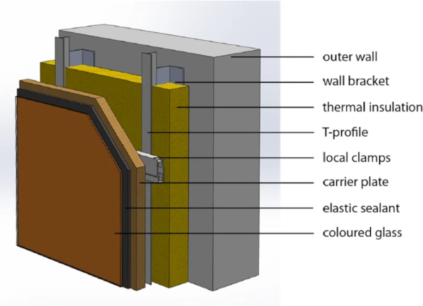
Whilst the construction has the advantage that glass acts as optimal protection against rain and humidity, the bonding process between the glass panel and the load-bearing carrier plate is time-consuming because the elastic sealant needs several hours to cure (Knaack and Koenders 2018). Figure 1 shows a typical construction of a ventilated façade with glass panes bonded onto carrier plates. The carrier plate is connected to the metal substructure using local fixings. The thermal insulation is positioned in the metal substructure. There is a gap between the carrier plate and the thermal insulation, which allows for a vertical airflow and gives the system its name.
The time-consuming production and the fact that the glass only acts as a non-load-bearing cover plate are the reason for the idea of the hybrid façade elements made of FRP and glass. Through the beneficial combination of both materials, the functional and optical properties are improved. The FRP consists of reinforcing fibres and a polymer matrix. The polymer matrix surrounds the fibres, which are bound to the matrix by adhesive interactions. Additionally, the polymer matrix also acts as an adhesive to the glass surface. The weather resistance of glass significantly improves the durability of the FRP. The façade elements are produced by direct lamination onto the glass pane. This eliminates the time-consuming process step of bonding glass and carrier plate. As such the glass provides the permanent formwork for the FRP. A broad colour spectrum can be achieved by pigmenting the matrix material. As a result, the use of coloured glass is no longer necessary, and the time-consuming process of enamelling can be omitted. A visual mock-up at GLASSTEC 2018 in Düsseldorf showed versatile colour designs (Fig. 2a).
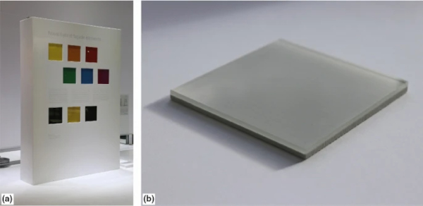
The novel composite panel allows the use of float glass. In addition to cost savings, float glass offers the possibility of water jet cutting after the production of the glass-FRP composite. This simplifies production. Figure 2b shows a sample of such a composite element. The FRP is coloured grey and the edges here are, as described, subsequently processed with water jet cutting. The use of FRP in façade construction has already been studied in other projects, i.e. (Tomasi et al. 2014).
However, the use of FRP instead of a conventional carrier plate for a ventilated system is not known. This article provides an insight into the project work that has been carried out and shows the potential of the material combination of glass and FRP. The choice of the components of the FRP is described in Sect. 2, while in Sect. 3 the combination of glass and FRP is examined. The results are used as a basis for discussing the load-bearing action of the hybrid component in Sect. 3.2.
Material selection
Investigation programme
The material selection process focused on a suitable price-performance ratio of glass and FRP. Hence, annealed float glass and glass fibres were selected as suitable for the intended application. Subsequently, an appropriate polymer matrix as well as a suitable fibre distribution was searched for by means of material testing.
The comprehensive material testing was divided into three phases: The pure matrix resin, the FRP and finally the combination of FRP and glass. The shortlist of the matrix materials was narrowed to a promising combination within the first two stages, which assessed the thermal and mechanical behaviour of each candidate.
In the first phase (see Sect. 2.2), six matrix materials were subjected to thermal analysis by means of differential scanning calorimetry (DSC) and dynamic mechanical analysis (DMA). Mechanical properties were derived from uniaxial tensile testing. The selection was reduced to three materials at the end of the resin tests. In the second phase (see Sect. 2.3) the remaining three matrix materials were reinforced with fibres embedded in different configurations. Uniaxial testing was conducted according to (EN ISO 527-1) to compare the performance of the FRP with the pure polymer without any reinforcement.
Further testing was done on the FRP materials to assess their behaviour in compression and to determine their coefficient of thermal expansion. Initially, four different configurations of glass fibres were tested, but two additional fibre configurations were added. At the end of the second phase a resin and two fibre configurations were determined as favourites. In the third phase (see Sect. 3) the combination of glass and the preferred FRP were examined in a four-point bending test and the residual load bearing capacity was defined.
Resin
The material properties of FRP can be adjusted by the choice of the polymer matrix as well as by the type, quantity and orientation of the fibres. With increasing fibre content, the matrix takes on a purely protective and embedding function. Compared to the FRP, the plastic matrix has a lower density along with a lower rigidity and strength (Bank 2006). FRPs are almost exclusively made of thermosetting polymers. They have a low viscosity, due to which the fibre surface is easily wettable. In the case of fully wetted fibres, they are protected against environmental influences and allow a consistent load transmission (Pritchard 1999). Because of the low-temperature resistance of thermoplastics, they are less suitable to be used as resin. At a high ambient temperature, the risk of fibre failure due to shearing increases.
Beyond that, thermoplastics have an increased tendency to creep. There is a wide range of thermosetting resins available. The use of epoxy resins (EP), unsaturated polyesters (UP) or vinyl esters (VE) is preferred for the resin. All three of them offer different advantages. Unsaturated polyesters have a very good price-performance ratio and are versatile. Vinyl esters are suitable for oscillating and impact-stressed components. Epoxy resins have outstanding durability, good adhesive properties and low shrinkage. Due to their high price, they are used almost exclusively for high-stress components.
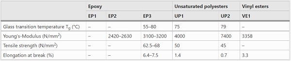
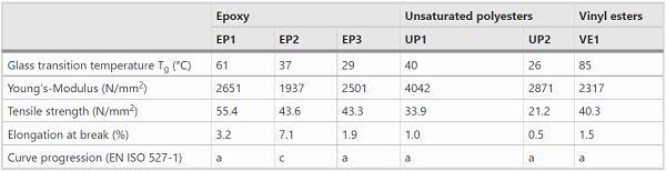
Three different epoxy resins, two unsaturated polyesters and one vinyl ester were examined. The commercial names of the matrix materials are not given in this publication due to confidentiality agreements. For a general overview, Table 1 lists the basic properties of the matrix materials according to the manufacturer’s specifications. Depending on the manufacturer, the information in the technical data sheets differs greatly in terms of quality or even to the point of missing information (marked by [–]).
Table 1 Material properties according to the manufacturers - Full size table
The curing conditions were evaluated using DSC analysis. The tests were carried out according to (DIN EN 11357). The tests showed that complete curing is achieved when the matrix materials are heated up to 80 °C for 2 h. All future test specimens were manufactured on this basis. Since the results from the DSC analysis did not contribute to the selection of materials, they will not be discussed in further detail in this paper.
DMA testing
In order to be able to choose a resin, extensive experimental testing was carried out. The thermomechanical behaviour can be examined using DMA. The test device is shown in Fig. 3a. The test specimen was subjected to an alternating load at different frequencies. In addition to the definition of the glass transition temperature, the time dependence of the material behaviour can be characterized by the frequency variation, and the viscoelastic characteristic values can be determined in a wide frequency range. The glass transition temperature is the temperature at which organic plastics pass from the glassy state into the flexible rubbery state. For this purpose, a small piece of cured resin was tested in tension mode.
According to the (EN ISO 6721-1), at least three test specimens should be available for testing a frequency range. In order to achieve a general orientation of the material characteristics, one test piece was initially subjected to a 1 Hz measurement under tensile load. For this purpose, the specimen was heated from − 60 to + 120 °C at a rate of 2 K/min. The evaluation was carried out in the range of − 25 °C and + 110 °C. In addition, three test specimens were then subjected to multi-frequency measurement under tensile stress. The measurements were used to characterize the curing behaviour and to estimate the displacement of the glass transition temperature as a function of the frequency. Frequencies of 0.01 Hz, 0.1 Hz, 1 Hz, 10 Hz and 100 Hz were tested at a temperature rising from − 33 to +100 °C at 1 K/min.
For the definition of the glass transition temperature range, its initial (lower) and final (upper) temperature values were determined. The temperature at the beginning of the glass transition temperature range were determined by applying two tangents to the curve of the storage modulus. One tangent lies ideally at the linear curve below the glass transition and one at the turning point of the steep slope. The intersection point was defined as the initial temperature of the glass transition Tg0. The final temperature Tge was characterized by the curve maximum of the loss factor. The procedure described in (ISO 6721-11) is shown in Fig. 3b. The storage modulus also indicates the Young’s modulus of the material. Whereby the storage modulus is usually somewhat higher than the Young’s modulus from the quasi-static tests due to its oscillating stress.
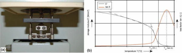
Figure 4a shows the comparison of the mean value of the glass transition temperatures from the multifrequency measurements. The size of the bars represents the frequency dependence of the matrix system. The averaged initial glass transition temperature from the 1 Hz measurement is shown in Table 2.
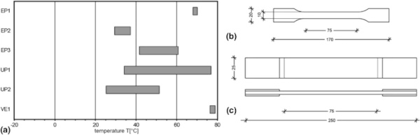
Table 2 Material properties obtained from the tests - Full size table
The following aspects must be taken into consideration when evaluating the glass transition temperature for material selection:
- The initial temperature values of the glass transition range Tg₀ should preferable be as high as possible, as it is related to a significant decrease of the stiffness properties. Ideally, the initial temperature values of the glass transition should be above the maximum operating temperature in façade construction, which is here assumed as Tmax = 80 °C.
- A wider glass transition range ΔT = Tge − Tg₀ usually has the advantage that the decrease in stiffness occurs more gradually. Therefore, some materials can meet the requirements even above the initial temperature value of the glass transition range.
- An increased frequency dependency indicates strong load-rate dependent stiffness characteristics. Thus, unexpected failure can occur under different loads. Therefore, a low frequency dependence is always aimed for.
If only the thermomechanical properties derived from DMA were considered, EP₁ and VE₁ showed the best results. They achieved the highest glass transition temperatures of Tg₀ = 61 °C (EP1) and Tg₀ = 85 °C (VE₂). The VE₁ was thus the only one of the six matrix materials examined whose glass transition temperature was above the maximum operating temperature. While the glass transition range of the VE₁ extended over ΔT = 18 K, the EP₁ revealed a glass transition extending over ΔT = 33 K. Both materials, EP₁ and VE₁, also showed a low frequency dependency (Fig. 4a).
Uniaxial tensile testing
The tensile test according to (EN ISO 527-1) is regarded as one of the fundamental tests of mechanical material testing of polymers. The universal testing machine can be used as a testing device for the quasi-static test. For the examination of the resins, the specimen type 1A (EN ISO 527-2) was used (Fig. 4b). The test specimen is loaded in tension until rupture occurs or any other termination criterion is reached. During the test, the applied loads and elongation are measured. The strain is measured optically using video extensometer. Following (EN ISO 527-1), five test specimens were tested in each case. Within the framework of the work, a strain rate of 1 mm/min was selected to determine the Young’s modulus. All tests were carried out at room temperature.
Since plastics have only a small elastic deformation range, the modulus of elasticity is determined by means of a secant in the range of 0.05% and 0.25% of the normative strain. In this range the material deforms linearly viscoelastic (Grellmann and Seidler 2015). According to Hook’s law, the Young’s modulus was calculated from the ratio of the change in stress ∆σ to the change in elongation ∆ε. The stress σ is formed from the quotient of the measured tensile force and the initial cross-sectional area. In addition, the failure stress σB with the associated elongation at break εB was obtained as important comparative values from the tensile test. The failure of the specimen was accompanied by a force drop to 10% of the force value. To enable a direct comparison with the manufacturer’s data from Table 1, the elongation at break was also evaluated (EN ISO 527-1). The results can be found in Table 2, whereby the presentation of Table 1 was used as a guide.
Comparing the Young’s moduli with each other, the UP1 reached the highest values. However, in the UP1, the Young’s modulus determined from the tensile test differs considerably from the Young’s modulus determined from the DMA analysis results. The UP2, EP1, EP3 and the VE1 also achieved high Young’s modulus. The EP1 showed the highest tensile strength. The EP2 achieved the highest elongation at break (εB = 7.1%) and was the only material that failed in a ductile manner, whereas all other materials failed brittle. The UP2 achieved the smallest elongation at rupture.
EP1 and VE1 showed the highest glass transition temperature. Since both materials also achieved consistently good results in tensile tests, they were selected for further use. The unsaturated polyesters both had a glass transition temperature which was too low for the intended façade application. In addition, they only achieved low elongation at break and tensile stress values. Upon request of the project partner, the UP2 was nonetheless also examined in combination with the fibre material, as this was the only one of all the matrix materials examined to have a fire-retardant additive applied. Thus EP1, UP2 and VE1 were selected.
FRP
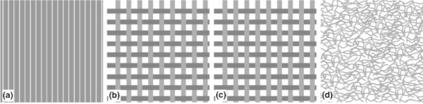
There is a large number of different fibrous materials, which differ in material, length and arrangement of the fibres themselves. Fibres are the stiffening component in the FRP. A strong atomic bond between matrix and fibres is therefore necessary (Campbell 2010). In the research project only glass fibres in different fabric forms were investigated. For the use in planar components, flat, textile semi-finished products such as mats, fabrics, or cloths are suitable. Initially, four different configurations of glass fibre fabrics were tested (see Fig. 5): (a) a uniaxial strap (US), (b1) a canvas fabric with an additional fibre mat (d) on one side (C-M), (b2) a pure canvas fabric (C) and (c) a twill tissue (TT). In the uniaxial strap, the fibres are unidirectional (Fig. 5a), resulting in just one main fibre direction.
Fabrics, however, are long, interwoven continuous fibres oriented in at least two directions. The difference between the twill tissue and the canvas tissue is the order of the warp and weft threads to one another. With the canvas fabric these alternate (Fig. 5b). This results in a high crossing density and a high degree of resistance to slippage. Due to the high fibre curvature, however, these are also weakened. With twill tissue, on the other hand, the weft thread passes over two or three warp threads (Fig. 5c). Although the shear deformation is reduced by the lower crossing density, the fibres also have an increased resistance to pressure and fatigue in return. In mats, there are short fibres which are distributed randomly within the matrix material (Fig. 5d). They contribute to a relatively isotropic, but at the same time less stressable, material behaviour.
All proposed fibre configurations were embedded in the selected resins. Uniaxial tensile tests were carried out to investigate the effects of adding fibres in the matrix materials and the effects of different fibre configurations. Biaxial fabrics have the same material properties in the two main fibre directions and are therefore tested parallel to only one of these main directions and diagonal to the main directions. The uniaxial glass fibre strap has only one main fibre direction and has been tested both parallel, perpendicular and diagonal to the fibre direction. In Fig. 4 c) is shown the test specimen type 3 according to (EN ISO 527-4). The test procedure is otherwise identical to that described in Sect. 2.2. The results of the Young’s modulus and the maximum tensile stress are shown in the following diagrams (Figs. 6, 7).
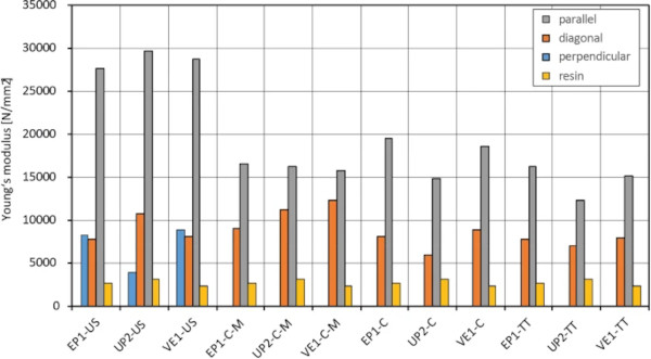
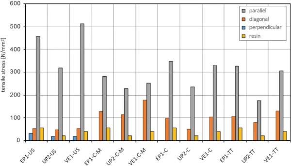
As expected, the best results relate to the tests where the load is applied parallel to the main fibre direction. The highest Young’s modulus was achieved by testing the uniaxial strap (US) parallel to the main fibre direction. However, the uniaxial glass fibre tape also showed the most significant drop in failure load if tested in any other direction. The results of other fibre configurations—canvas-mat (C-M), canvas fabric (C) and twill tissue (TT)—differ only marginally from each other. Except for unsaturated polyester, the uniaxial glass fibre tape showed approximately the same results when tested perpendicular to the fibre direction.
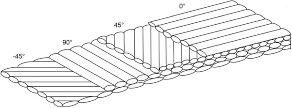
The strong anisotropy of the uniaxial glass fibre ribbon is problematic for the intended application. On the other hand, the uniaxial ribbon was convincing due to its significantly higher Young’s modulus. Based on these findings, a quadrax mesh was added to the product range. The quadrax scrim has a layer structure consisting of four differently oriented layers. Each layer is offset by 45° to the previous layer, which means that one layer of the fabric offers a fibre orientation in both main directions and two diagonals (Fig. 8). As the quadrax scrim is also one of the most expensive fibre form variants, a pure glass fibre mat was also tested. This could be used instead of the quadrax scrim in the cross-section part that was exposed to less stress.
Based on these results, the epoxy EP1 was chosen for the further progress of the project. It achieved consistently high values and showed the smallest variations in the test results. Following the choice of materials, uniaxial tensile tests were performed once more. As the fibre mat shows an almost isotropic material behaviour and the quadrax fabric has a fibre aligned in all four directions, it is not necessary to perform the tensile test in several directions. The results of the tensile test for the two preferred material combinations are shown in Fig. 9 and Table 3. The non-reinforced epoxy resin has a Young’s modulus of 1937 N/mm2. The FRP with the fibre mat achieves a Young’s modulus of 8516 N/mm² and the FRP with the quadrax scrim a Young’s modulus of 13632 N/mm². Although the stiffness values are lower than those of the twill and canvas fabric, they do not depend on the direction of loading.
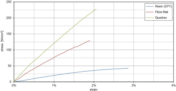
Table 3 Experimentally determined transverse strain coefficients for the selected materials - Full size table
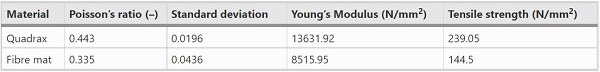
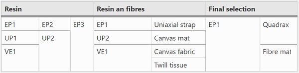
Additionally, the Poisson’s ratios of both FRP configurations were determined. Biaxial strain gauges were used for this purpose, which measure both longitudinal and transversal strain in the tensile test. The results are presented in the following Table 3. Table 4 summarizes the material selection process.
Table 4 Schematic material selection - Full size table
Glass-FRP composite
Two different layer structures were considered. One consists of pure quadrax scrims. Therefore, a very high fibre content and the best possible mechanical properties can be achieved. The alternative construction has a core of fibre mat. Due to the substitution of the cost-intensive quadrax layers in the less stressed core, costs can be reduced. Basically, FRP should always be built-up symmetrically. In order to keep the shear stress between the glass and FRP as low as possible, the neutral axis should be at the contact area between both materials. Assuming full composite behaviour, this is the case with a thickness ratio between glass and FRP of approximately 1:2 (Joachim 2017).
In theory, the various fibre reinforcements have different advantages. The quadrax scrim consistently delivered the best results. However, the price-performance ratio of the fibre mat was convincing. For the four-point bending test, 5 mm thick glass panels were used, resulting in a FRP thickness of 10 mm. The following two different laminate build-ups were developed:
- Ten layers of quadrax scrim.
- Two top layers of quadrax scrim on each side and a core of eight layers of fibre mats.
The first laminate structure guarantees the highest fibre concentration and, as a result, the best mechanical properties due to its high fibre orientation and the fact that the fibres in the quadrax scrim are in a flat plane rather than undulating as is the case for fibres in a woven fabric configuration. The second laminate, in turn, can reduce production costs thanks to the low-priced fibre mats and also result in almost homogeneous material properties in the core of the FRP. The cover layers act as load-bearing layers in the area of maximum stress.
Four-point bending test
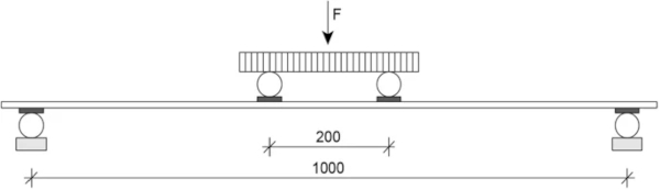
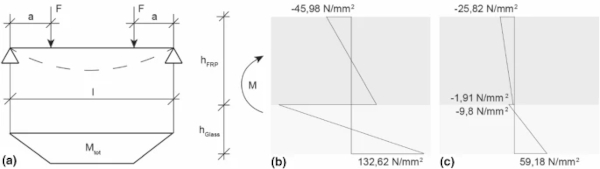
In practice, the façade panels are mainly loaded in bending. A standard four-point bending test for glass is used to assess the load-bearing capacity of the composite elements. The bending test for FRP is usually carried out according to (EN ISO 14125). However, to obtain comparable results, all tests are performed in accordance with (EN 1288-1), which is typically used to determine the bending strength of glass. Wherever possible, though, the specifications of (EN ISO 14125) for the bending test on FRP are followed, apart from the significantly larger test specimen dimensions. In the four-point bending test, schematically shown in Fig. 10, a panel of 1100 mm in length and 360 mm in width was supported at a distance of 1000 mm. The force was applied at the centre and evenly split on two points 200 mm apart from each other, and increased continuously (EN 1288-1).
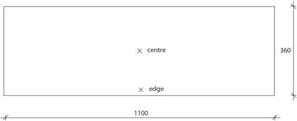
Due to the “Poisson effect”, an additional stress field perpendicular to the span direction is generated. This effects a counter-bending in the transverse direction, which means that the longitudinal stresses are no longer uniform. The result is an increased bending stress along the longitudinal edges and a reduced bending stress in the centre of the panel. Because of this effect, all specimens were equipped on both sides with strain gauges at the mid-span of the panel—one in the central axis and one close to the edge, as shown in Fig. 11.
Both panel build-ups of the final selection were tested in four-point bending. Load was applied from either side of each panel configuration. Hence, the bending tests assessed both the performance of the panel with the glass surface in tension and with the FRP-side in tension. A number of 3 samples per panel configuration were assessed under the same test conditions. Thus, 12 test specimens were tested. The specimens tested in this study met all requirements of (EN ISO 14125) with regard to the geometry.
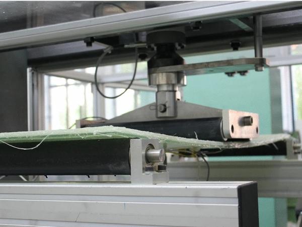
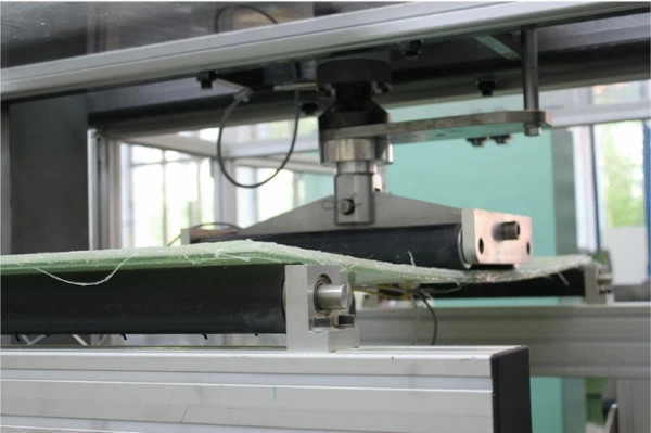
The samples are loaded stepwise with 200 N and a holding time of 1 min, up to a maximum load of 2000 N. The tests are performed at room temperature. Figure 12 shows the test setup and a specimen with the glass side facing downwards.
The strain in the four-point bending test is linear in the thickness direction between the negative strain on the top side and the positive strain on the bottom side of the glass. The strain as well as the elongation depend on the material stiffness. As a result of the changing fibre orientation, the stiffness of the FRP laminate changes in layers. And, as a consequence, there are discontinuities in the stress profile. The results from the four-point bending test were compared with the analytical calculation in Sect. 3.2 and are discussed.
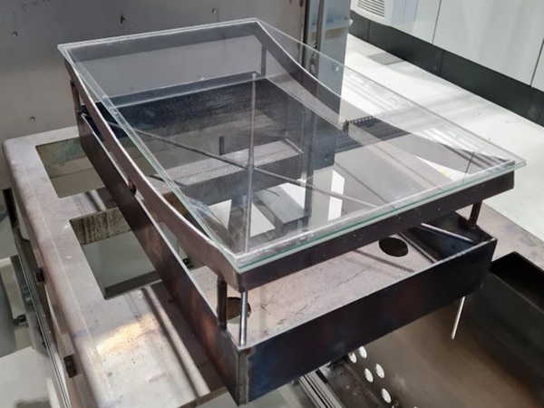
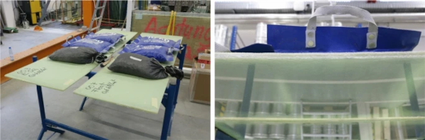
None of the specimens failed during tests. Nevertheless, the residual load-bearing capacity of the composite panels was assessed in further tests. A sufficient residual load-bearing capacity and the protection of people against falling shards are essential aspects when glass is used. The residual load-bearing capacity was verified in a horizontal position. The test specimens were loaded by a weight of 30 kg using sandbags (Fig. 13). The glass on the bottom was broken at several locations. The residual load-bearing capacity was guaranteed over a standing period of 48 h. The test was carried out both on test specimens with float glass and additionally on test specimens made of fully tempered glass. In the tests carried out, the glass, both float glass and fully tempered glass, adhered very well to the FRP.
Even with conventional laminated glass with polymeric interlayers of, for example, polyvinyl butyral (PVB) or ethylene vinyl acetate (EVA), this means that the elements achieve a comparatively high residual load-bearing capacity (Overend et al. 2014). With standard laminated glass, the adhesion of the broken glass to the interlayer is responsible for the increased residual load-bearing capacity. When using annealed glass or heat-strengthened glass, the broken glass pieces interlock with each other, providing a sufficient residual load-bearing capacity once again. Laminated sheets of FRP and glass also have the further advantage that, in addition to the adhesion of the glass to the resin, the load-bearing capacity of the FRP itself leads to a higher residual load-bearing capacity compared to standard laminated safety glass.
Comparison with an analytical calculation
In order to be able to classify the composite action of the novel façade panel, the results of the four-point bending test were compared using an analytical calculation assuming full composite action and no composite action as layered limit. Figure 14 shows the resulting stress profiles in the midspan of the composite panels made of FRP and glass. The blue area shows the glass and the grey area the FRP. Thus, in the representation chosen here, the glass lies in the zone subjected to bending tensile stress. The surface tension can be calculated using the strain measured in the four-point flexural test and the Young’s modulus determined from the tensile tests. An approach of a new analytical model, albeit not applicable here, is presented in Pascual et al. (2017).
In this paper the authors consider the axial and shear stresses produced by local response versus global response. However, the sandwich element used differs greatly from the panel built-up chosen for the study. Especially since the FRP is bonded to the glass by means of an adhesive instead of the matrix material serving as an adhesive at the same time, as in the example given here. Nevertheless, a similar approach to stress profile was examined here as well. In their contribution, Overend et al. (2014) also depict the stress profiles of a sandwich element made of two glass faces and a shear-resistant glass core enclosed in polymeric intermediate layers. They demonstrate the strain and stress profiles of the composite element under bending stress with intact and broken core.
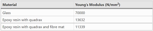
The Young’s moduli listed in Table 5 were used. The combination of a fibre mat and quadrax scrim is calculated from the two experimentally determined Young’s modulus according to the quantity proportions.
Table 5 Young’s moduli used for stress calculation - Full size table
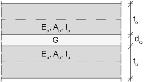
The deformation with layered limit, calculated according to beam theory, was taken after the Bernoulli hypothesis. Figure 14a) shows the resulting stress profile. Figure 14b, c show the stress curve for full composite action. For that, the sandwich theory was used, assuming full coupling between the elements. The following Fig. 15 shows the structure of the sandwich element according to Stamm and Witte (1974). The upper part of the sandwich component, with the index “O”, represents the FRP range. The lower part of the sandwich, index “U”, represents the glass. For the calculation, the assumption G → ∞ and dQ → 0 is made. The stress discontinuity between the two materials in Fig. 14 originates from the different Young’s moduli.
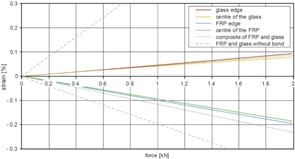
In the four-point bending test for pure glass, there is a linear curve in the thickness direction between the negative strain on the upper side and the positive strain on the bottom side of the glass. Since both the stresses and the strains depend on the material stiffness, alternating stiffnesses occur in the load direction in the FRP laminate layers as a result of the changing fibre orientation and consequently jumps in the stress curve in the thickness direction. As a result, the outcomes of the four-point bending test are not presented in the usual form of stress–strain diagrams, but as force-strain diagrams.
Figure 16 shows an example of the diagram of a plate made of quadrax scrim and glass with the glass on the side subjected to bending tensile stress. The dashed lines show the analytically calculated strain-force behaviour under full composite and layered limit. The two lines on each side (FRP and glass) represent the previously described sample preparation by two strain gauges on each side. The centre of the specimen undergoes an equal or greater stress compared to the edge of the specimen.
Except for minor deviations on the FRP side, the results of the four-point bending test are consistent with the analytical calculation assuming a full composite. The experiments showed that the combination of FRP and glass forms a hybrid element (Weller and Pfalz 2018). This result is consistent with other research such as Achintha and Balan (2017, 2019). Up to a load of 2 kN, there is no difference in the strain-force curve between the two selected FRP lay-ups, which is why a panel consisting of quadrax and fibre mat is not shown here.
Conclusion and future work
The experimental tests on small parts showed the different material properties resulting from the choice of matrix material and the type and quantity of fibrous materials. This is the reason why the choice of material is made with great effort. However, the actual focus of this research project was to investigate the combination of glass and FRP in terms of their composite action. The experimental tests showed significant coupling between the glass and FRP. In addition, the comparison with the analytical solution shows that the glass-FRP interaction is close to full composite action. For the first time the glass pane is part of the load transfer and can go beyond its previous function.
Therefore, the structure can be considerably slimmer than before, and material can be saved. A further aesthetic advantage is the possibility of colouring the FRP. The FRP can take on any desired colour. Thanks to this and the high residual load capacity of the façade elements, float glass can thus be used. Float glass is much easier to work with, as it can be cut after bonding with the FRP by water jet cutting and makes it possible to create a clean edge.
Also during the production of the test specimens, a significant advantage over conventional carrier plates with glass as the top layer became apparent: as the glass acts like a kind of formwork for the FRP, no equipment is required for manufacturing, which can be started without much preparation. In comparison to a conventional carrier plate system, where the glass is bonded to the carrier plate as weather protection and an optical element, as described in Sect. 1, the resin works not only as a matrix material but also as an adhesive bond to the glass. Which means that bonding as a separate production step is not needed.
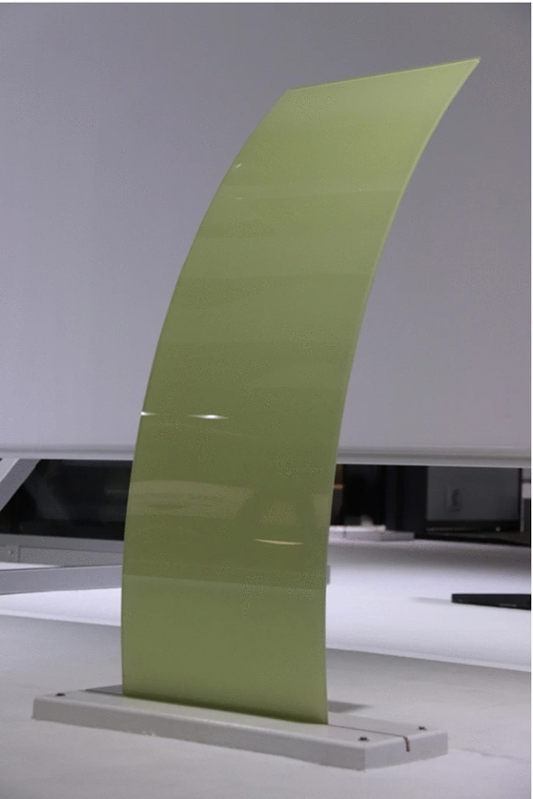
In addition to the numerous advantages, such as weight and material savings, cost reduction and simplified production, the material combination of FRP and glass offers further great potential: Previous ventilated rain screen façades made of glass and a conventional carrier plate were exclusively available in flat design. The newly developed glass-FRP composite offers the possibility to construct curved elements, since the FRP material is geometrically unrestricted. Figure 17 shows an example of such a curved element.
In consideration of the high potential that results from the combination of glass and FRP, the authors recommend further investigation of the composite action. This includes further, extensive experimental test series that support generated results and take other aspects into account, such as is the performance of the panel under thermal cycling. When combining different materials, the effect of the different coefficients of thermal expansion must always be examined. As a result of thermal cycles, the component can be subjected to forced loading and, in the worst case, fail. Initial tests have already been carried out in this area as part of the project, but a more thorough investigation is needed. Other types of stress that play a role in façade construction should also be examined. Depending on the planned area of application, these include, for example, impact loading or high cycle mechanical fatigue.
References
Acknowledgements
The research project “FKV-Glas-VH Fassade” is funded by the research programme “Zentrales Innovationsprogramm Mittelstand” (BMWi/AiF). The authors thank for the financial support for the research project. Furthermore, we would like to thank FIBER-TECH Products GmbH for the cooperation and the provision of materials as well as test specimens.
Funding
Open Access funding enabled and organized by Projekt DEAL. Funding was provided by Bundesministerium für Wirtschaft und Technologie (Grant No. ZF4123705HF5).
Author information
Authors and Affiliations
Institute of Building Construction, Technische Universität, Dresden, Germany - Alina Joachim, Jan Wünsch & Bernhard Weller
Corresponding author
Correspondence to Alina Joachim.