Challenging Glass 6
Conference on Architectural and Structural Applications of Glass
Louter, Bos, Belis, Veer, Nijsse (Eds.), Delft University of Technology, May 2018.
Copyright © with the authors. All rights reserved.
ISBN 978-94-6366-044-0, https://doi.org/10.7480/cgc.6.2158
Authors:
Philipp Eversmann, University of Kassel, Germany
André Ihde, TU München / Pfeifer Hebe und Seiltechnik Memmingen, Germany

The demand for transparent but robust designs in architecture is still enormous. One of the most complex points of the application of glass is the use of efficient and appropriate connection details. The article examines a modular glass system about its architectural possibilities with a special focus on the connection methodology. We constructed a 2 x 2 x 1m prototype of specially laminated glass sheets with integrated connection details in the framework of a Master of Science programme on digital fabrication with support from Seele and Bischoff Glastechnik, which was also featured in two public exhibitions at TU Munich and the House of Architecture in Munich.
The design potential is investigated using parametric geometrical modelling as well as FEM sensitivity analysis. At the interface between the architect and the engineer, the consequences of the FEM analysis are discussed reflecting the influence of the chosen connection to the peak stresses within the structure and expected deflections. A typical part of the examined structure is prepared as an FEA-model. The abstraction of the connection details within the model allows a more in-depth analysis of the load transmissions between the glass panes using non-linear contact effects as well as the rheological behaviour of the interlayer material. The examined structure was designed for application in small-scale architectural design.
Beside the design, and analysis of the structure fabrication and installation aspects and their consequences to the design is explained in detail. Unique aspects of this article are new possibility to build transparent and efficient façade systems that can be flexibly adapted to possible areas of application due to the parametrically supported design processes. In addition to the design process, the direct interaction between the architect and the engineer was also able to consider the aspects of the data exchange regarding de tail development. The article concludes with a description of further development for full-scale architectural applications and the necessary research.
1.Introduction
1.1.Structural Glass in Architecture
Glass has been used for structural applications already since the last century (Rice and Dutton 1995) and has a wide range of architectural possibilities (Nijsse 2003). Ledbetter et al. give a good overview of structural applications of glass (2006). For safety and loading issues, laminated glass in used in most cases. Laminated glass for architectural glazing applications consists of two or multiple layers of glass bonded to a thin thermoplastic interlayer, usually polyvinyl butyral (PVB). The resulting assembly has desirable structural advantages over monolithic glass regarding impact resistance and moderation of postfracture glass fallout and also provides better sound attenuation and ultraviolet radiation absorption (Behr al. 1993).
1.2.Structural Glass Joining
Glass connection systems have been optimised in recent years (Overend 2005), especially in the recent versions of Apple stores (O'Callaghan 2012) up to very few amounts of steel elements necessary for structural bonding. Blandini realised a glass dome with glued structural adhesives (2007). Nevertheless, to the author's knowledge at the point of writing, no demountable joint exists without the use of steel elements.
1.3.Homogeneous Glass Joints
In this paper, we describe a novel method of a Glass-dovetail (GD) connection system which doesn’t require any steel connectors. In section 2, we describe the computational design method using a voxel approach (2.1), assembly detailing (2.2) and structural design (2.3) incorporating the modelling method (2.3.1) and the FE-Analysis (2.3.2). In section 3, we show the digital fabrication and assembly techniques used for a large-scale prototype. In section 4 we analyse and compare results and conclude in section 5 by relating further development for full-scale architectural applications and necessary research.
2.Computational and Structural Design
2.1.Computational Design
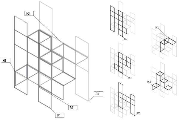
This study was done for the application of an exhibition pavilion. The architectural idea was to use a glass exhibition case as the basic element for generating the geometry of the overall structure of a cloud-like appearance. We employed a computational design method using voxel elements. The word voxel originates by analogy with the word "pixel", with vo representing "volume" and el representing "element (Foley 1990). We realised quickly that constructing complete voxels of glass would require a large amount of material and also double sheets between each voxel element. We, therefore, developed a computational method to generate only a part of each voxels’ faces, which were necessary for structural and functional reasons. This resulted in decomposition of interconnected faces that still evoke the impression of complete voxels depending on the angle and superposition of glass sheets in the structure (Fig. 1).
2.2.Detailing
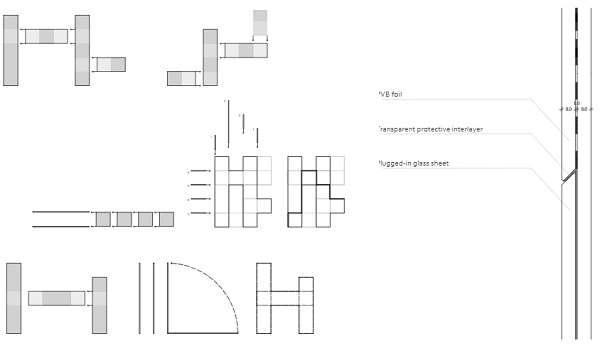
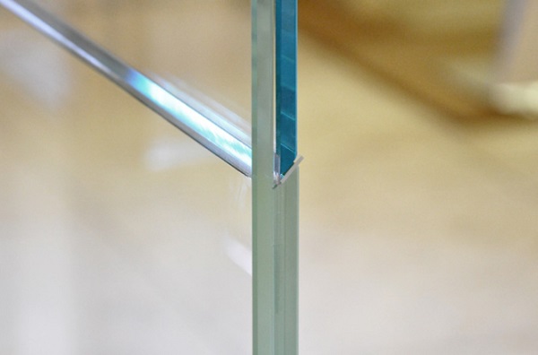
The detailing of the structure went through multiple iterations. In a first step, we ordered and connected the voxel faces into a series of vertical frames and horizontal connection plates. For the vertical frames, we developed a plug-in system of sheets of 3 laminated glass layers with integrated holes and connection elements. This proved to be too difficult to realise taken into account fabrication tolerances, and excess polyvinyl butyral (PVB) foil problematic to evite. We, therefore, developed a double-layer system of laminated sheets with 45° chamfers on the edges, which would block sheets after insertion, similar to dovetail connections in timber connections. We used acrylic distance elements of thin sheets to eliminate direct contact of the glass edges and allow for sliding during insertion (Fig. 2).
2.3.Structural Design
The finite element analysis aimed to determine the influence of the glass-dovetail (GD) connection method about:
- the overall deflection due to horizontal wind loads,
- the location and magnitude of glass stresses,
- the modelling effort to include the GD connection method into a larger structure.
2.3.1.Finite Element modelling method
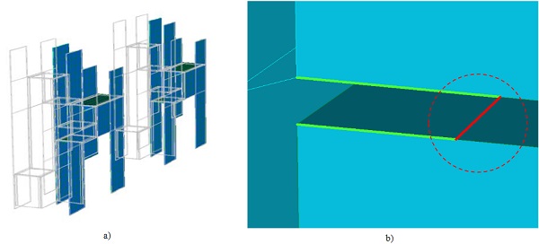
For the FEM analysis, a typical section of the overall structures (see Fig. 3a) was chosen to model and analyse the behaviour of the GD connection using the general FEM-Software Strand7. The abstraction of the joints was governing the modelling method. We modelled the glass panels as Quad4 plate/shell elements and isotropic material behaviour. We realised the coupling of the glass panels with PVB foil through a rubber-like material with the law by Mooney-Rivlin (bulk-modulus 1000 Mpa, C1 =1.6, C2=0.06) as described in (Timmel et al. 2007). Along the connection line of two neighbouring Quad-elements, we integrated a zero-gap element in a 45° angle (red marked in Fig. 3b), which only allows the load transfer of a negative axial load (compression) and a small amount of friction (friction value 0.05).
We also used zero-gap elements for the regular glass to glass joints as well as for all regions where the glass panels are not connected by a PVB foil to allow only a load transfer due to direct contact of the glass surfaces. Besides the gravity load (load case 1) we also applied a wind load of 1KN/m² (load case 2) to the structure in the global y-direction. Since the auto-meshing tools provided by the FEM software did not show any usableresults, we programmed a mesh with the precise matching of adjacent FEM nodes using Rhino / Grasshopper. To create a second FEM-model with a more monolithic behaviour, the discussed zero-gap elements were converted to full connected link elements.
2.3.2.FE- Analysis
A direct comparison of the two modelling methods shows that the FEM-model with the fully linked glass panels has a 42% lower deflection under the 1KN/m² test load (see Fig. 4). That means that the influence on the overall deflection behaviour can be considered as significant under realistic wind loads.
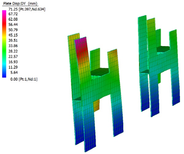
The overall stress distribution of the two comparison models are similar, but the first FEM Model (with zero gap elements) shows high-stress concentration near the connections, so the peak stress in this model approximately doubles compared to the monolithic structure. Fig. 5 shows the comparison of both structures under the same load.
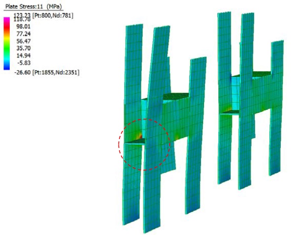
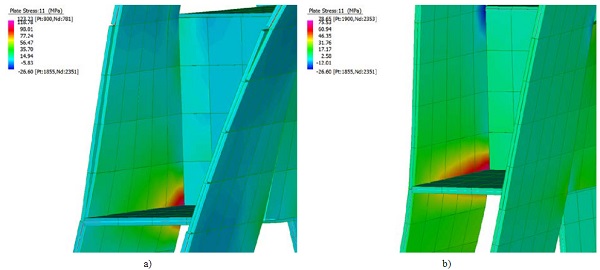
The first FEM Model shows singular peak stress of 123 MPA (Fig. 6a) while the monolithic structure reaches only 78 MPa (Fig. 6b) at the same location. Also visible in Fig. 6b is the enlarged opening of the glass connection as well as the warping in the area without a PVB bonding.
3.Digital Fabrication and Assembly
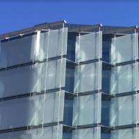
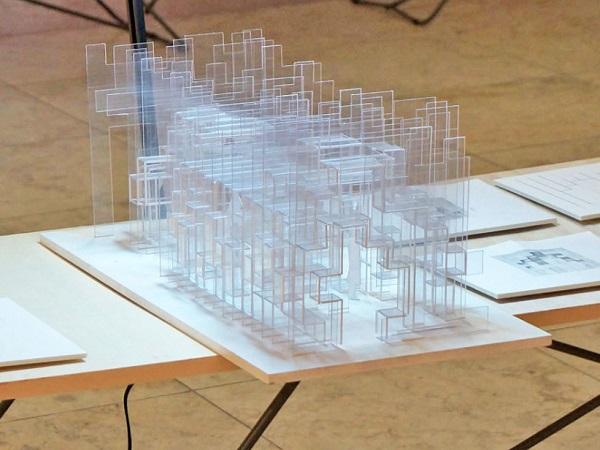
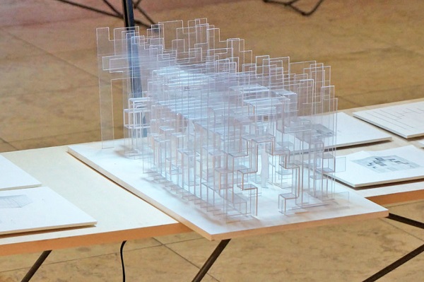
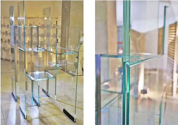
Through a collaboration with the firm Bischoff Glastechnik BGT, we were able to realise a large-scale prototype of around 2 x 1 x 2m (h). The prototype consists of three vertical frames and their horizontal connecting glass plates (see Fig. 7). All elements consist of double-layer laminated glass sheets and were digitally cut and manually assembled for lamination using distance holders.
The vertical frames were connected and assembled through the Glass-dovetail connection system described in section 2. The GD-connection details were CNC-milled. For assembly, we used thin acrylic sheets to allow the glass sheets to glide and prevent direct contact of the glass edges (see Fig. 8). For the horizontal glass sheets, we used pairs of demountable stainless-steel elements which we glued to the vertical frames using acrylic foam tape to allow the structure to be mobile and easily transportable.
4.Results
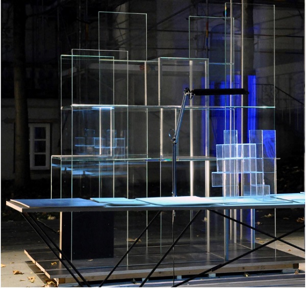
In this research, we described a modular structural glass system of specially laminated glass sheets with an integrated novel connection detail using a principle similar to dovetail joints in timber construction. We analysed this novel method through parametric modelling with a voxel-based approach as well as highly detailed FEM sensitivity analysis. Through industry collaborations, we were able to realise a 2 x 2 x 1m prototype which was also featured in two public exhibitions at TU Munich and the House of Architecture in Munich (Fig. 9., Fig. 10).
The prototype demonstrates that homogeneous glass joints can be designed for larger structures. Regardingstructural analysis, these types of joints are challenging and require considerable modelling effort. The FEM comparison indicated that the GD joint significantly influenced the magnitude of resulting peak stresses and deflections of the structure. It can be stated that a reliable simulation of such a connection is possible, but requires more efficient meshing techniques that should be subject to further research.
5.Conclusion
This article demonstrates a new possibility to build transparent and efficient glass systems that can be flexibly adapted to a range of architectural applications due to a completely integrated parametric design and fabrication workflow. At the current state of research, the structural glass construction method of this research could be imagined in a scale of small-scale architectural design or for parts of façade structures. For more extensive scale applications, research needs to be done on the fabrication and assembly procedure due to the considerable weight of structural glass systems and their challenging manoeuvrability. To compensate for higher stresses, this kind ofconnection would require thicker glass panels or additional laminated layers. This disadvantage needs to be balancedwith high flexibility referring to transport and novel assembly systems. Further investigation could lead in the direction of mixing different glass thicknesses within one structure to overcome singular stress peaks and develop a more detailed and elaborated positioning system for these kinds of joints.
Acknowledgements
This research was supported by the Technical University Munich in the course of a quest professorship program at the chair of envelope structures. The design of the prototypes was done in collaboration with Dr. Philipp Molter and the students Adrian Ben Djebbour and Stefani Wolf. We would like to warmly thank Erwin Trommer of Seele and Martin Sulzer of BGT Bischoff Glastechnik AG for their support, technical insights and contributions.
References
Behr, R. A., J. E. Minor, and H. S. Norville.: Structural behavior of architectural laminated glass. Journal of Structural Engineering 119.1 (1993): 202-222.
Blandini, L.: Structural use of adhesives for the construction of frameless glass shells." International journal of adhesion and adhesives 27.6 (2007): 499-504.
Foley, James D.: Andries van Dam; John F. Hughes; Steven K. Feiner.: Spatial-partitioning representations; Surface detail. Computer Graphics: Principles and Practice. The Systems Programming Series. Addison-Wesley. (1990) ISBN 0-201-12110-7.
Ledbetter, Stephen R., Andrew R. Walker, and Alan P. Keiller.: Structural use of glass. Journal of architectural engineering 12.3 (2006): 137-149.
Nijsse, R.: Glass in structures—Elements, concepts, designs, Birkhauser, Basel. (2003).
O'Callaghan, J., and Bostick.C.: The Apple Glass Cube: Version 2.0. Challenging Glass 3 (2012): 57-65.
Overend, M.: Optimising connections in structural glass. Proceedings of 2nd International conference on Glass in Buildings. (2005).
Rice, Peter, and Hugh Dutton. Structural glass. Taylor & Francis, (1995).
Timmel, M., et al.: A finite element model for impact simulation with laminated glass. International Journal of Impact Engineering 34.8 (2007): 1465-1478.