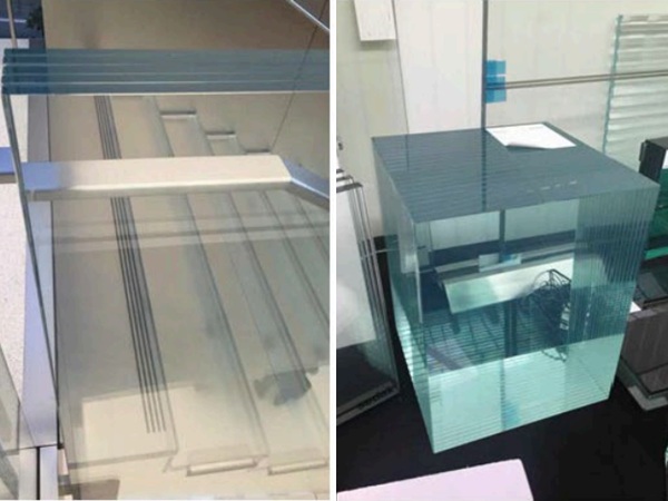
The “U”-shaped, linear cast-glass channels are self-supporting and mounted in an extruded metal perimeter frame to provide a truly distinctive architectural feature.
A Popular daylighting system for interior or exterior glass walls, channel glass – such as Pilkington Profilit™, available from Technical Glass Products (TGP), Kirkland, Washington – provides a sleek, modern look for commercial or industrial buildings and homes. The glass is available in a variety of colors and textures with varying translucency, allowing for the passage of natural light without loss of privacy. This very versatile product can be installed vertically or horizontally and is available in lengths up to 23 feet, with either tempering or filming options available to meet impact safety requirements.
Because of the shape of the system, it can achieve very tight radiuses or can be used in serpentine applications. Intermediate vertical mullions are generally not required for vertical installations. Additional benefits include strong thermal performance, sound transmission control and adaptability to seismic code requirements.
Given the distinctive nature of channel glazing, some specific guidelines must be followed for proper installation. While not difficult or complex, the steps differ from more traditional glazing materials. The following guidelines provide general instructions for installing the product in exterior vertical applications. As with any specialty glazing, consult the supplier’s documentation for specific installation instructions, including procedures for horizontal or interior installations.
Preparing the Structural Opening
Prior to fitting, the supporting structure must be checked to ensure that it is square, plumb and in plane. The support jambs must be plumb. All surfaces should be checked to ensure that they are suitable for attachment and conform to the contract documents.
Measuring and Attaching Aluminum Frames
Measure the opening sizes and cut the head, sill and jamb sections. Miter or cope and butt the joints at the head. Cope and butt joints at the sill.
When measuring the frames, take into account the caulking bead clearance requirements and shim with the appropriate-sized horseshoe-type plastic glazing shim. Expansion properties of the aluminum frame should be taken in to consideration. Consult the supplier for specific details.
To attach the aluminum frames to the structure, place all fasteners approximately 12 to 18 inches on center (300 to 450 mm), or as recommended by the engineer of record. Fasteners should be located no closer than 6 inches from the corner joints. Couple frame members exceeding 24 feet in length with an expansion joint material as supplied by TGP.
The specific type of fastener required depends on whether the supporting structure is concrete, steel or wood. Refer to manufacturer’s table for typical types of fasteners for the various applications.
At all head/jamb mitered corner joints, install aluminum corner keys and internally seal corners with approved silicone. At sill/jamb coped and butted corner joints, a screw boss is provided for corner assembly. After assembly, care must be taken to internally seal all joints.
Cut and fit plastic inserts into the head, jamb and sill sections of the frame. The vinyl inserts at the jamb should be fitted to the full daylight height of the opening and clip securely into the frame. The horizontal head and sill vinyl comes pre-cut to length to match the glass sizes and should be place intermittently (to match glass placements) in the sill and head of the frame. Finally, insert foam baffles into exterior weep holes.
Cutting channel glass
Tempered glass and annealed (at customer’s option) glass can be provided cut to length. If glass is desired, or required, to be cut on site, the following procedures should be followed:
• Place the glass channel on a flat surface, preferably cushioned with felt or other suitable materials. With the flanges pointed upward, channel glass channels can be cut by hand or by special saw. There should be a minimum glass bite allowance of ¾ inches (20mm) for the head and jamb and ½ inches (13mm) for the sill. The flange cut (jamb) channels must have a bite or at least ¾ inches (20mm).
To cut by hand:
• Use a cutting template or straight edge to ensure a straight cut.
• Begin by scoring the flange furthest away, starting at the corner and working upwards; return back to the corner of origin and start the cut across the face of the glass and continue up the flange closest to the cutter in one continuous motion.
• Make a light glancing blow to the top edge of the flange opposite the cut on each side of the glass channel.
• Place the glass-cutting tool under the glass channel and apply light pressure to the flanges of the glass to snap it cleanly across the cut line.
• Ensure that the ends of the channels are free from chips, cracks or bad cuts (pay particular attention to the quality of the cut at the corners, there should be no notches or shark’s teeth in this area). Seam the ends of the glass with a disc or belt sander specifically designed for glass edging, taking special care to smooth any irregularities caused by cutting.
Installing Glass

Before installation, clean all internal surfaces of the glass with an alcohol-based glass cleaner. Apply the 166 flange gaskets on each flange of every channel. The gasket application is most effective if the material is stored in a shaded location prior to installation.
The gasket should be held ½ inch from the end of the flange on one end and flush with the edge of the flange on the opposite end (e.g. a 96-inch channel would have a 95-½ inch 166 flange gasket). The recessed portion of the gasket is always applied to the bottom end of the channel.
Installation of the glass channels can begin at either the center point of the opening or at either end. Shop drawings are typically provided to indicate starting point and number of channels to be used for a specific elevation. Consult TGP for the size of joint between the channels.
Typically, these joints are 1/8 inch, but the size can sometimes vary depending on the requirements of the contract documents. The jamb channels at either end of the glazed opening must have a minimum glass coverage of ¾ inch (20mm), or as otherwise specified. The flange cut/jamb channels are typically inserted prior to the installation of the last full-size channel.
Pocket glaze the channels by inserting into the plastic liners located in the head and then lowering the glass down onto the corresponding plastic insert located in the sill. Suction cups are typically used to aid with this procedure. To ensure that the spacing between the channels is consistent, place 1/8-inch plastic shims at the head and sill of each channel as it is being installed.
Sealing the System
Prior to the application of any sealant, check glass joints for consistency and plumb. Install special channel glass shims across internal and external joints and seal all glass-to-glass and glass-to-aluminum joints with approved silicone sealant. For 1/8-inch glass-to-glass caulk joints, it is not necessary to use backer rod. The caulk joint at the perimeter of the frame should be packed with the properly sized backer rod and the approved, specified sealant should now be applied to the perimeter joint.
Although the installation process for channel glass such as Pilkington Profilit involves some specific steps and techniques that differ from standard glass, experienced glaziers can install the product without hassle using these basic guidelines.
By Ms. Tysen Gannon and Mr. Peter Alberini
Tysen Gannon is the product manager for Pilkington Profilit, a channel glass offered by Technical Glass Products (TGP), Kirkland, Washington. Peter Alberini is the technical sales manager for TGP. www.tgpamerica.com 1-800-426-0279