First presented at GPD 2017
On the other hand, both parties are also expecting smaller, more slender structural elements that are challenging in terms of code compliance. Both aims may be satisfied using Hybrid Glass Structures (HGS). Combining glass panels with another structural material could contribute to the total structural performance of a building, with efficiencies that allow for material savings and a reduction in construction time. Guidelines outlining HGS on the analysis, basis of design, methodology and constructability are currently considered inconsistent.
This paper intends to review existing projects that include HGS in order to assess the adequacy of the structural scheme and materials used. Commonly, materials consist of steel/stainless steel or fibre reinforced polymers. This paper will include a literature review opening up to a broader state-of-the-art review to develop knowledge on this theme. An example of existing structures with numerical studies are presented and the potential benefits of HGS quantified.
1 Introduction
Engineers are expected to propose the efficient use of natural and human resources to a design problem specified by the client in their brief, architectural intent and national / international regulations and code of practice. A problem is never trivial and design space is multi-parameter; engineering judgment is as important as technical knowledge.
In the current, competitive climate, consultants are asked to deliver original designs with, perhaps, a controversial performance brief. More often than not, design consultants offer their clients a multidisciplinary and global service to provide a holistic design approach. As such, a multidisciplinary team of experts (from many fields of expertise) will cooperate closely to develop a bespoke solution. It is important for engineers to drive innovation and research in growing areas of the construction business that allow for quick and effective answers to client demands, while at the same time developing solutions that are sustainable, practical and deliverable. This topic is explored in more detail in [4].
The concept of combining materials to produce desirable characteristics that differ from those possessed by the individual materials themselves is not a new concept. Wilkinson and Monier’s 19th Century composite of iron bar embedded in concrete is still a concept used widely in the construction industry today. It is worth noting that in composite materials, the individual component materials remain separate and distinct.
Materials can be categorised according to their characteristic properties and for each subcategory advantages and disadvantages can be listed as per particular design situation.
2 Performance criteria
As mentioned earlier, the engineer is responsible for compliance with client, architecture brief and design codes of practice. Efficiency can be measured by total material use per unit volume, but cost tends to be used to compare different schemes.
This is because the quantity surveyor will incorporate scheme complexity such as procurement, constructability, access and maintenance and risks associated with above activities alongside with material costs. Innovative (or complex) design concepts such as HGS require upstream investment and development to ‘mainstream’ it as reliable structural solution that may be disseminated to all the involved parties within the construction environment, and hence reduce costs.
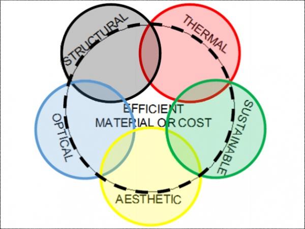
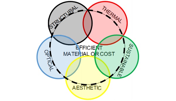
This study has identified five main aspects where schemes comprising of glass in combination with other material(s) have been a success story. Precedents have been gathered from past projects and projects being currently developed.
2.1 Structural
Outlined below are key structural qualities when designing with structural glass. Further information can be find in [5]:
• Redundancy – duplication of critical component to increase reliability of system;
- Passive: extra strength, no. of elements
- Active: prevents overstressing
• Ductility – ability of relatively high energy absorption capacity due to the material yielding;
• Robustness – ability of system to cope with change without being damaged to an extent disproportionate to original cause;
• Resilience – ability to absorb or avoid damage without suffering complete failure and recover within reasonable cost or time;
Improving in service performance or post failure behaviour of HGS could be achieved on an elementary level:
• Reinforced with steel, timber, FRP,GRP glass edges, to increase strength, stiffness from rectangular flat plate to T, I sections. Such reinforcement may switch failure mode of the HGS component from brittle to ductile.
• Lamination of glass panes with interlayers and polycarbonate sheets is well known technique to increase redundancy of the element.
• Edge rods, profiles, may contain failed element and as such improve robustness of the glass element. Concept successfully proposed by Dodd [3] on the Constitution Bridge in Manchester where measures to increase public safety was required.
On a material level, glass may be combined with other materials that complement the lacking characteristic properties of glass. Particular attention to the differential thermal expansion and thermal capacity of the materials shall be given, as well as the magnitude and distribution of connection forces between components and failure mode prediction. After the literature review we summarised materials considered by researchers and designers as:
• Metals - Stainless steel, Aluminium, Titanium; [12], [13]
• Hard and soft timber, Engineered timber composites; [8], [9]
• Polymers, and cement based materials as FRP, GFRP, GFRC; [10], [11]
Glass in structural systems can differ in form; planar, single or double curved geometry have been explored. Internal composition of the structural form is closely linked with geometrical orientation. Short summary of possible structural systems are outlined:
• Predominantly bending structures, with a structural skeleton spaced further apart consisting from flat 1D or 2D elements. Concept often used to maximise transparency, however potentially resulting in larger elements which may hinder visual perception;
• Diffused glass structure with a smeared metal skeleton. Traditional greenhouses of 19th century are considered highly transparent despite the relatively closely spaced steel bars;
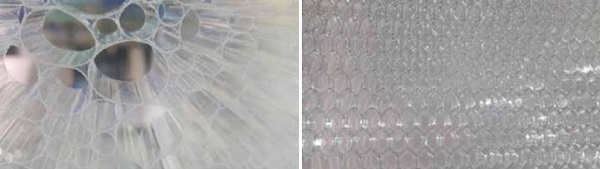
• Sandwich glass elements; [6]
• Membrane;
• Compression; (glass bricks)
• Shear walls and stability elements (reinforcing diaphragm in tensile nets or traditional steel frames).
2.2 Thermal
With the increasing financial and environmental cost of the energy, designers are focusing their efforts on improving thermal performance of building envelopes. Another increasingly important parameter to consider in the design is the shading coefficient as reducing cooling demands is a high priority of envelopes comprising of high ratio between transparent and opaque areas. A shading device may be integrated into the structural system and recently dynamic shading components or switchable glass was researched by many teams with new exciting products emerging on the market.
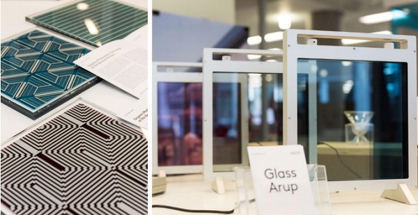
Over past years we have developed and perfected our envelope detailing to mitigate energy loss. Today we are investing our efforts in harvesting some of the energy to create energy passive buildings. Some examples of the latest generation of PV cells thermo /photo chromic glass are presented on figure above. Interesting prototype of Glasstex arch was built by a team led by Jan Wurm and Ralf Herkrath in 2002 for the Glasstec fair in Dusseldorf.
The design was motivated by evenly distributed light to prevent overheating as such desire to integrate solar shading into the structural concept was developed. The structural system is a complex cable stabilised compression glass arch with bottom tension cables connected with fabric shades and longitudinal forces.
Similar concepts to integrate shading devices into the cavity of insulated glass units was outlined in [7]. The micro louvers in the glazing cavity help to provide Sun and glare protection. Z-profiles can be employed to optimise solar shading and provide full protection when sun is high in the sky.
2.3 Sustainability
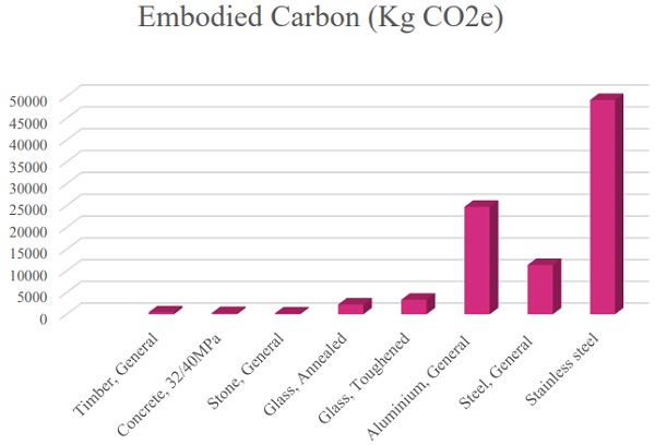
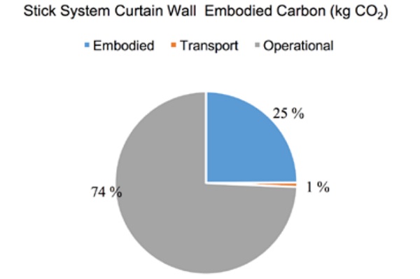
The graphical data illustrated on figure below shows the embodied carbon of a variety of typical façade materials. Additional fabrication processes of annealed glass such as heat treatment, heat soaking, lamination, edge polishing and coating can more than double the embodied carbon footprint of the final product. However it is expected that above processes will improve product performance and as such reduce operational carbon footprint.
2.4 Optical
The visual performance of glass may be specified as either transparent, opaque, or both/in-between. Furthermore, the transparency of glass may (appear to) be dynamic. Optical quality, distortions and reflections shall be reviewed as they may have an influence on the perception of the final product.
2.5 Aesthetic
Glass, when combined with other materials, is a unique solution with unlimited possibilities for clients, architects and engineers. Aspects such as natural/artificial light, reflection and shadows are usually considered in conceptual design stages. Furthermore, the process of combining materials should strive to enhance structural integrity.
The concept of total transparency is challenged by increasingly prominent environmental requirements that are in favour of an alternative concept of diffused transparency. In diffused glass structures, a holistic approach of ‘layering’ (and where possible, integrating functions) helps to minimise cost and develops a product with desirable properties.
3 Selected applications
3.1 Structural IGU Panel
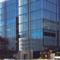
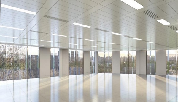
Architects are intrigued by uninterrupted views and as such often tend to specify facades without vertical mullions or horizontal transoms. In this particular example, architectural intent is to provide maximum transparency between opaque elements by omitting framing in the visual zone. This provided the engineer with a challenge to design floor to floor glazing panels which are 3 side supported with the middle panel only two side supported top and bottom.
Displacement compatibility at the edge was a considerable issue here. To avoid increasing glass thickness and thus cost and weight to the primary structure, all panels were connected with a structural silicone. Structural silicone is stiff enough to transfer shear forces from the ‘softer’ middle (two side supported) panel to the stiffer three side supported panels and as such equalise system deformations.
However, to limit out of plane edge deformations to the acceptable industry limit of L/175 and reducing durability risks of the insulated glass units, two sets of two glass panes of 12mm thick laminated glass were required. This is around 50% more glass than on a typical curtain wall system (per m2 of elevation) with mullions.
As briefly touched on earlier, researchers and industry focus on connecting both inner and outer glass panes together to benefit from the increase of inertia moment. The shear coupling co-efficient introduced by interface slippage can be theoretically calculated. The build-up offers improved structural performance. Such structural insulated glass units must be designed to withstand climatic loads. Alternatively units can be pressure equalised and connected to the external desiccant container to mitigate climatic stress and water condensation within the cavity.
This strategy was successfully used in many projects including the recent Berkeley Hotel, development in London completed by Bellapart and design by our colleagues from Arup. [6] Our initial studies focused on the development of the edge connections between the outer and inner pane of the insulated glass units using finite element analysis.
Traditionally, this seal is semi-structural and usually consists of an Aluminium spacer bar filled with desiccant, butyl adhesive and structural silicone (predominantly acting as a secondary seal to prevent moisture ingress and air/gas leakage.) Triple insulated units are becoming increasingly common in order to increase the thermal performance of building envelopes. Larger spacing between outer and inner glass panes in the triple insulated panels may significantly increase structural performance of the element.
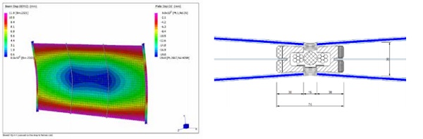
Fig 8 Conceptual detail of triple insulated curved panel made from thin laminated glass
a. four side supported panel, standard system
b. two side supported panel, no composite action between glass panels
c. two side supported panel, partial composite action, connection modelled with spring element
d. two side supported panel, partial composite action, connection modelled with plate element
e. two side supported panel, partial composite action, connection modelled with volumetric element
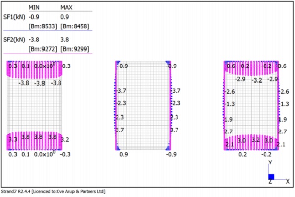
Effect of the edge bonding has been parametrically studied on the array of panels. In this paper we will only present results for panel with 2m width and 3.35m length. Connection edge stiffness with elements of generic stiffness of E=100mm, nu= 0.45, t= 25mm have been considered in this example and results presented in the graphs below.
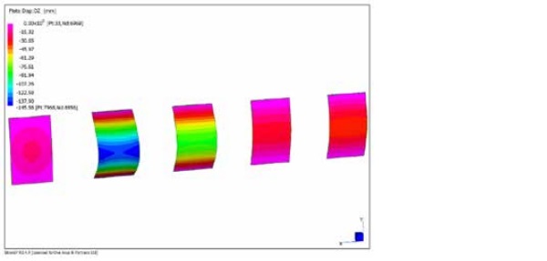
In addition, three conditions were studied where connections between outer and inner glass panes were considered on short, long and both edges of the panel. Peak shear forces in the connection element are presented on the figure below. While the peak shear force for short and long connection is almost equal 3.8 kN, 3.7 kN respectively, a smaller shear force of 3.2 kN was calculated located in the shorter edge for both edges.
Deformation analysis of the above panel revealed that short edge connections contribute least to the overall panel stiffness with peak mid panel deformation of 59.3mm. The long edge connection provided slightly improved composite action with peak deformation of 51.7mm, while if all edges were connected the deformation peak was 35.8mm.
From discussions with the Architect, it was clear that the width of the bond on the long edges should be kept to a minimum as those are key visual obstructions, while the less active bond on the short edge could be potentially increased in depth as it is usually hidden within the top and bottom connection within the opaque panels between ceiling and floor.
As such the top connection was modified and depth increased to 75mm. Decrease in overall deformation from 35.8mm to 28.9mm was noticed, not as dramatic as hoped for. However, a further study will be required to understand this phenomenon in greater detail and as such optimise this concept for practical application. The following graph summarises deformations and neutral axis stress.
It is clear from the neutral axis glass stress plot that a very linear stress distribution is noticeable in the case of the short edge connection. Longer effective width of 561mm was calculated as well in comparison to the effective width of 420mm for the modified all edge condition. The methodology as outlined in [1] and [2] was used to calculate effective width of the structural insulated panel.
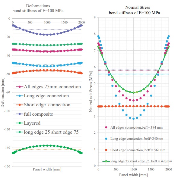
a. Deformation plot at mid span through panel width
b. Neutral stress plot at mid span through panel width
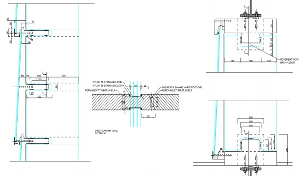
3.2 Glass / Timber Pavilion
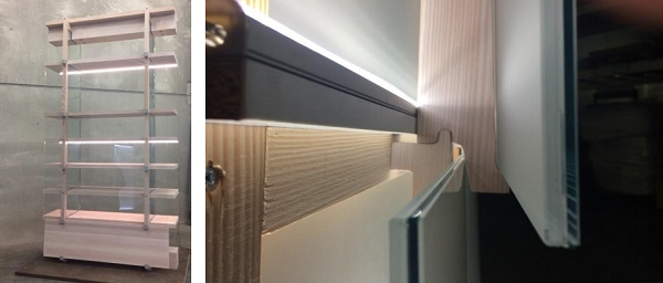
London based architectural studio Friend & Co. won a competition for the new V&A shop with a 6m tall glass pavilion. A main volume is ground supported with a top vertical movement joint to accommodate floor movements. This volume initially comprised of a 6.0m tall, 400mm deep glass fins spaced up to 1200mm from each other. Glass fins were designed as simply supported beams.
However, due to the fast track program and long procurement time of the jumbo size glass components available from mainland Europe only, a late design change was introduced to reduce fin size to approximately 3.5m. A second smaller volume attached to the main volume is a 3m tall by approximately 2.5m x 2.5m size in plan. This volume is top hung. As such separation via a movement joint was specified. Again, glass fins as primary structural elements were value engineered after tender stage.
A non-traditional combination of glass and timber was envisage by the architect. From a strength perspective, both C24 softwood and D40 hardwood would be capable of safely transferring loads. However tight deflection limits limited material selection. One potential issue was the shelf dimension at 400mm.
This is on the extreme end of the dimensions available for a solid piece of timber. Typically hardwoods come in larger dimensions (being larger diameter trees) but this depended on availability within the UK market, Alternatives were outlined, namely engineered timber products such as LVL, or glued connections of multiple solid timber planks.
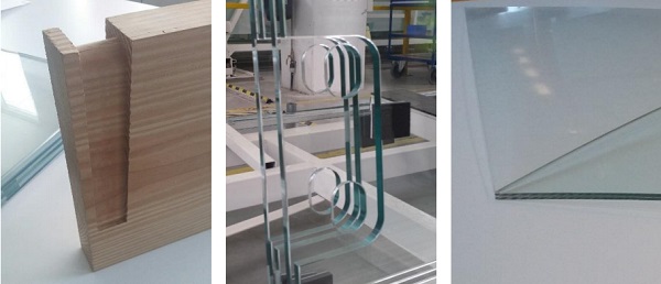
Timber shelves are connected to the glass fins via extremely narrow glass notches. Due to the high stress concentrations at fin notches, heat strengthened glass was specified. Triple laminated glass consisting of 12mm thick panes were considered to provide enough bearing to the timber.
Polished edges are specified for the glass fins which are particularly difficult due to the notch shape. The pavilion is cladded form outside with glass shingle. Annealed glass is specified to deliver superb visual quality and lightweight appearance. Thin glass laminate was proposed in the early design stages. However due to the procurement time traditional double laminate consisting from 3mm thick glass was ultimately installed.
A series of finite element analyses were carried out to justify the feasibility of the scheme. Global deformations of the global system were within few millimetres. The glass fin was analysed with shell elements and notches of 200x 40mm were explicitly modelled to check local stress concentrations in the glass. It should be noted that good quality of workmanship – glass polish in this zone was achieved.
4 Conclusions and summary
Examining previous Arup projects and projects recently built by others, it was realised that the concept of hybrid glass structures should be reviewed from a wider perspective. Key areas were identified that our clients have been interested in when designing with structural glass.
Clients are now interested in holistic design (i.e. combination of multiple performance criteria’s rather than structural excellence only.) This requirement is what will define hybrid glass structures of the future. The knowledge from this paper has been disseminate on current Arup Facade Engineering projects.
Acknowledgements
Invest in Arup fund 077359-54, Chris Noteboom, Patrick Rogers, Luis Soares Martins, James Griffith, Vladimir Marinov, and Graham Dodd
References
[1] Amadio, C., Fragiacomo M., 2002 Effective width evaluation for steel–concrete composite beams Journal of Constructional Steel Research 58 (2002) 373–388
[2] Bin Zou, et al, 2011 Evaluation of effective flange width by shear lag model for orthotropic FRP bridge decks, Composite Structures 93 (2011) 474–482
[3] Dodd, G., Reed, L. 2014, Anchoring Triangular Glass Panels to Prevent Collapse, Challenging Glass 4 Conference on Architectural and Structural Applications of Glass, Bos, Louter, Belis (Eds.), 2014.
[4] Lenk, P., 2016. : Designing with Structural Glass, Challenging Glass 5 Conference on Architectural and Structural Applications of Glass, Bos, Louter, Belis (Eds.), Ghent University, 2016.
[5] Lenk, P. Honfi, D., 2016. Resilience, Damage Tolerance & Risk Analysis of a Structure Comprising Structural Glass, engineered transparency, Dusseldorf 2016
[6] Teixidor,C.,2010, Glass – Honeycomb Composite Panels, Challenging Glass 2 Conference on Architectural and Structural Applications of Glass, Bos, Louter, Veer (Eds.), TU Delft 2010.
[7] Wurm, J., 2007, Glass Structures, Birkhäuser, Germany 2007
[8] Kozłowski M., E. Serrano E., Enquist B., Experimental investigation on timber-glass composite I-beams, Challenging Glass 4 & COST Action TU0905 Final Conference – Louter, Bos & Belis (Eds) 2014
[9] Antolic D., et al, Laminated Glass Panels in Combination with Timber Frame as a Shear Wall in Earthquake Resistant Building Design, Challenging glass 3 conference on architectural and structural applications of glass, 2012
[10] Valarinho L., et al., Numerical simulation of transparent glass-GFRP composite beams using smeared crack models, Proceeding of the 6th International Conference on Fibre-Reinforced Polymer (FRP) Composites in Civil Engineering (CICE 2012)Rome 2012,
[11] Louter Ch., et al., Structural Glass Beams with Embedded Glass Fibre Reinforcement, Challenging Glass 2 – Conference on Architectural and Structural Applications of Glass, Bos, Louter, Veer (Eds.), TU Delft 2010
[12] Bos, F.P., Stainless steel reinforced and posttensioned glass beams Pappalettere, C (Ed.), International conference on experimental mechanics / icem12 / advances in experimental mechanics, Bari 2004
[13] Feldmann, M., Abeln, B., Richter, C., Experimental and Numerical Studies of the Nonlinear Structural Behaviour of Bonded Steel-glassfaçade elements Subjected to Multi-axial Loading, 2nd International Conference on Structural Adhesive Bonding, Porto 2013