Work presented includes the Osaka Maritime Museum, Changi Airport T3, the Partheonon Gallery, Athens as well as 3 Pacific Place and One Island East in Hong Kong.
1 Introduction
Structural glass has become a commonplace component in architecture. Early pioneering work on structural glass that created the spherical bearing articulated bolts for suspended tempered glass and tensile cable wind bracing cable trusses was carried out by Peter Rice and the RFR group at la Villette, Paris in the early ‘80’s. The author had the good fortune of participating in that project and co-authored Structural Glass with Peter Rice [1] telling the story of the development process.
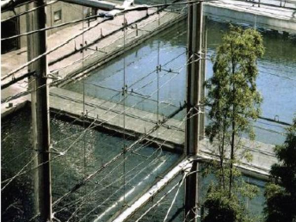
Figure 1: Facades Bioclimatiques La Villette
For HDA, it is the architectural potential of structural glass that is the most appealing to me. At the time, maximal transparency was the objective of our work. The architect of the museum, Adrien Fainsilber, wished that the Museum have an open dialogue with the park, using the south facing Bioclimatic Facades as a ‘zone tampon’ between the museum and the park. The glazing system consisting of 2m x 2m panels of tempered glass were suspended from each other using investment cast components in stainless steel. An entire bay measuring 8m x 8m is an autonomous structural glass panel gravity supported by the glass itself and using the glass surface to stabilize the cable system. The ‘cable truss’ was developed as an alternative to glass fins. The cable truss itself was a pioneering development of non-linear analysis engineering at the time. HDA’s work has attempted to explore the architectural potential of structural glass, applying it in varied contexts with maximal attention to the architectural message of each case rather than an expression of the technology itself. There has been notable attention to the recent concerns of sustainable design.
2 Case Studies
The following selection of the HDA’s work is presented as evolution on structural glass architectural trends within our practice. the dates indicated for each project correspond to the time that design for each was carried out.
2.1 Osaka Maritime Museum –1995
Paul Andreu’s 73m glass dome in Osaka bay houses the cities collection of maritime history pieces as well as a full scale replica of the Higaki Kaisen sailing craft. HDA proposed a Lamella type lattice grid-shell structure for the hemispherical dome. The gridshell dimensions are determined as a function of maximal glazing dimensions, where four panels of glass at the equator are supported by the tubular compression frame, with their internal corner supported by the cross-over node of the ‘X’ of diagonal bracing.
Figure 2: Osaka Museum showing Lamella gridshell and night-time reflection of lamínate metallic interlayer
Beyond the structural performances of the dome, the glazing is also designed to minimise solar gain using an innovative adaptation of laminated glass. A perforated steel interlayer is introduced into the laminate with variable dimension holes whose sizes are determined as a function of the solar exposure.
The concepts of variable and relative transparency in this project are achieved through the perforated mesh, providing views of the surrounding seascape from the dome in the day and into the dome at night. Inversely, the views into the dome in the day are obscured because of the mesh’s performance in reflecting sunlight. Similarly, at night, the mesh performs the role of a ceiling that reflects the internal light of the space rather than a view of the black night sky. This entirely passive approach of controlling transparency, similar to traditional lace curtains in windows, simply exploits the fact that transparency is a function of relative light intensity. The eye always sees where there is most light. i.e outside the dome in the day and inside it at night.
Figure 3: Osaka Museum showing Daytime reflectivity and Nightime transparency of metallic interlayer
2.2 Three Pacific Place, Hong Kong- 2000
Pacific Place Three, a 40 storey office tower, is a recent addition to Swire Properties shopping and office complex located on the frontier between the Central commercial office/administration district and the Wan Chai community. The architectural ambition for the podium at the base is maximum openness and transparency such that the tower integrates itself with the surrounding small scale context.
A 20m high suspended structural glass façade is braced by a three dimensional cable net. The net is composed of convex curved vertical cables tensioned against a concave series of horizontal cables. The vertical cables are fixed to the ceiling and ground slabs, while the horizontal ones are fixed to the columns. Corners are complex cases where there multiple re-entrant glass planes. The net system responds to the individual cases by adapting its geometry to the support conditions, whilst still providing the wind load support for the suspended glass.
Figure 4: 3 Pacific Place cable net viewed from Queensway
Figure 5: Cable net corner
Figure 6: Cable net detail
2.3 Changi Airport Terminal 3 Departure hall facade- 2001
The airport is the front door of Singapore, and the facility is continuously modernized in the image of the garden city state itself. The local architectural team CPG, assisted by SOM of New York, collaborated with Hugh Dutton Associates (HDA) for the design of the facades of the building. The design strives to express the CAAS’s objectives of a contemporary image combining the themes of appropriate and ecological technology with transparency. T3 is a sober and minimalist composition of orthogonal surfaces and design with light.
Figure 7: Changi T3 Departure Facade
The frontispiece of T3 is the departure hall cable net façade. An exercise in discretion and transparency, it consists of a simple orthogonal grid of cables tensioned vertically between the roof and the ground slabs as well as laterally between the roof support columns with glass panels clipped to custom designed cast cable clamps. The cable net is a high deflection system, that depends on this deflection to develop resistance against an applied wind force. The net will deflect up to 30cm in maximum conditions. Such extreme values were simulated at full scale on a prototype 15m wide x 18m high of a typical bay of the façade . The suppleness of the cable system requires specific attention to the fixing details that must allow the movement and deflection of the glass, whilst still firmly fixing the glass in place.
Figure 8: Cable net and glass deflection analysis and glazing details
Rather than use bolted glass, it is clipped using more discreet patch fittings that use EPDM rubber bearing pads for the movement capacity between the glass sheet and the stainless steel of the castings.
2.4 Parthenon Gallery-2003
The return of the Parthenon Marbles, removed by Lord Elgin, has long been a strong ambition of Greece, and a competition was held to design a new home for them at the foot of the Acropolis. Bernard Tschumi’s winning design proposed a rooftop gallery in glass to the exact proportions of the Parthenon itself, that would put the marbles in their original context but protected from the elements. HDA were commissioned by the Greek Ministry of Culture to assist in the technical design for the glass envelope with the challenge to find the best possible solution to the fundamentally contradictory objectives of optimal transparency and maximum solar protection.
Figure 9: Parthenon Gallery glass wall during construction showing suspension rods and fins
The glass wall design uses a double skin with a second layer situated inside the external wall. This double layer creates an air corridor or glass chimney in the void between them. The outer skin is in insulated glazing that incorporates a high performance coating and is ‘fritted’ with dots of black paint to protect against infrared radiation to prevent over heating inside the Gallery. The internal skin is in single layer glass on the upper levels only, so that the lower level outer skin glass at viewer’s height is left as minimal as possible. Shading screens are included for the most exposed South, East and West elevations. Cool air is introduced at the bottom edge of the glass all the way round the Gallery facade. The air that enters at the bottom of the ‘glass chimney’ heats up by solar radiation, either directly from the sun or indirectly by absorption in the glass or on the blinds. This heating up causes the air to rise naturally up to the top of the void where it is mechanically extracted. This flow of air limits the rise in temperature of the internal skin to around 23°C when the external temperature is about 40°C. The north elevation, with the view to the Parthenon itself, is not obstructed with shading. Low iron glass is used to minimise colour change in the light. Fritting, or printed ceramic dots on the glass surface, provide complementary glare protection.
Figure 10: Double Skin ventilation concept
Figure 11: Parthenon Gallery glass wall detail
The two glass skins are suspended from the roof edge using glass fins. These fins are cantilevered from the steel structure above into the glass chimney space, perpendicular to the two glass skins. The glass fins must resist wind loads of up to 150kg/m².The weight of the glass itself or the dead weight of the glass which is about 2,5 tons for each row of glass panels, is supported on small stainless steel rods and minimal cast brackets. These fittings provide a fail-safe security in the event the fins break. The entire system was tested for full design wind load and safety margins of up to 220kg/m².
2.5 One Island East, Hong Kong -2005-6
In Hong Kong’s Quarry Bay, a new landmark tower has recently been completed on the city skyline by Swire Properties and architects Wong and Ouyang. Consistent with an economically optimal design strategy, at the ground level, where the users can get up close and appreciate a tactile quality in the building, an exceptionally crafted facade treatment is used for the lobby glass wall. Careful attention is paid to the quality every connection and component of the glazing system. The curved glass and softness of the cast steel components of the podium glazing render it thematically consistent with gentle curves of the building profile itself.
The glazing system proposed by HDA for the glass wall uses fins suspended from the first floor and propped of the suspended floor edge and cantilevering below it The fins therefore stop above ground level, such that the lowest level of glass at eye-level does not need any framing or support, despite the fact that the hall is more than 12m high. It is therefore as transparent as possible where it can be most appreciated by the users.
Figure 12: Typical bay of pódium facade showing facade truss and props to first floor suspended deck
The glass wall is suspended from the level 2 floor edge. The fins find horizontal support at the deck level using a facade truss in duplex stainless steel. For as minimal an appearance as possible, diagonals were not desired. Therefore the truss works as a Vierendeel for shear capacity. A central spine in the glass plane is assisted by cast spreader arms projecting both inside and outside whose tips are linked by an external tie rod. For positive wind loads, the inner rod is loaded in tension and in negative suction winds, the outer one is in tension, while the corresponding compression requirement is provided by the spine itself for both cases.
The spreader brackets are in two halves, such that they clamp either side of the glass fin, allowing it to project continuously through the truss plane. The brackets are in cast stainless steel as is the spine. All components are Duplex grade, with an elastic limit of 460MPa for optimal visual lightness. The truss gravity loads are supported by thin suspension straps on either side of the fins.
The concept analysis was carried out on a full finite element model incorporating steel and glass components modeled as shell and block elements using Strand7 analysis software. Individual details were individually analysed. Particularly detailed analysis was carried out in the glass holes to understand the local stresses and component sizes.
Figure 13: Finite element analysis of curved bay
The glass fin is half inside and half outside the glass plane. As such its 800mm depth is not fully felt inside. Each fin is gravity supported at the facade truss. It is realized in two pieces in tempered laminated glass. It is spliced mid height at a point of minimal bending moment in the fin to diminish the loads on the sensitive holes in the glass. The splice is realized in cast stainless steel in a butterfly shape according to the pattern of the forces it resolves. The fin edges are therefore exposed to the atmosphere. A Sentry Glass interlayer was used in response to concerns about the effect of humidity on it.
The lowest glass panel, whose height is determined by the maximum vertical spans achievable with unsupported vertical edges, is suspended from the tips of the fins using a custom designed casting and countersunk bolts. All other panes are gravity supported from the metal components of the system: the upper row on the splice casting, the second row on the facade truss and the third row on the casting at the tip of the fin.
Figure 14 Spreader detail shown in concept sketch and on test mock-up.
The lower tips of the fin are themselves cut to a gentle taper, compatible with the progressively diminishing shear loads in the fin, to soften their impact.
Figure 15 View of facade and curved fin tapers.
3 Conclusions
HDA’s work using structural glass is an attempt to put it to the service of architectural concepts rather than as an expression of the technology itself. Applications include complex geometrical surfaces such as the Osaka Museum. The work attempts too to address the issue of sustainable design, through the inclusion of shading in laminates, as well as the hot climate double skin application in Athens.
4 References
[1] Rice, P.; Dutton, H.: Structural Glass, Paris: Le Moniteur 1991
AUTHOR:
Hugh Dutton
Designer, Founder of Hugh Dutton Associates
Keywords: Structural Glass, Cable Truss, Transparency
This article was originally published on the blog complexitys.com.