First presented at GPD 2017
Abstract
Building with glass as structural element becomes more and more common. Under special boundary conditions like in alpine areas or near the coast this might become a challenge concerning design and execution at the building site. Important points are the climatic conditions in alpine and maritime regions, like extreme wind loads, extreme pressures for insulating glass units due to the difference in altitude, salt water near the sea, narrow installation situations and a narrow time slot. Basics and applications of glass constructions in these extreme boundary conditions are presented. Two summit stations with glass applications, the Nebelhorn (2224m) and the Zugspitze (2962m) and a pavilion located in the Baltic Sea are presented.
1 Introduction
Glass as a building material is used in a multitude of new applications like modern glass façades or transparent railings. New ways of fixing the glass and almost a boundless freedom in size and shape offer a plentitude of solutions for these issues. From the architect’s point of view glass balustrades and facades in alpine regions should be as transparent as possible (magnificent view), but simultaneously they have to act as a protective barrier and load bearing element (enormous loads). The situation is similar with buildings in touristic areas near the sea. Experienced structural engineers can satisfy both sides of the same coin.
2 Glass as structural element
Glass is used more and more as structural element. Structural element means that the glazing is exposed to actions like wind, snow, line loads, impact and climatic loads in case of insulation glazing. This requires for almost all glass constructions like facades, railings and canopies a careful design and structural analysis.
Glass is a brittle material. Hence it is very important to consider stress peaks, e.g. resulting from the constraint with point fittings or internal corners. Bonded connections have to be analysed in a close to reality structural model.
By means of a temper process, the strength of the glass can be increased. Three levels of prestressing are commonly distinguished:
- annealed glass (float glass) with a tensile strength of 45 MPa,
- heat strengthened glass (HSG) with a tensile strength of 70 MPa and
- fully tempered glass (FTG) with a tensile strength of 120 MPa.
Enamellings reduce the above characteristic values.
Apart from above bending strength the different behaviours of breakage and the different remaining load carrying capacities must be taken into account. Usually laminated safety glass (LSG) is used (two or more layers of glass with an elastic interlayer made of PVB) to increase safety in case of breakage. But PVB is not the only interlayer material for laminated safety glass, other interlayers with different properties are offered, too. E.g. the ionoplast interlayer behaves very stiff and it is not as sensitive towards increasing temperatures as ordinary PVB interlayers. FTG is breaking into very small fragments resulting in a poor remaining load carrying capacity. It can be increased by the use of above mentioned stiff interlayer.
As the use of glass in structural engineering is a quite new subject, only a few regulations and design rules exist so far. With the German standard DIN 18008 more applications are regulated, based on fracture mechanics and in line with the current concept of partial safety factors [2], [3], [4], [5], [6], [7]
3 Boundary conditions in alpine areas
In alpine and maritime areas, specific boundary conditions must be taken into account:
- Extreme weather conditions with high wind and snow loads.
- Difficult access to the building site.
- In case of insulated glass units (IGU) extreme differences of air pressure and temperature between manufacturing and installation site.
- High UV radiation might cause problems of aging of bonds and sealants.
- High salt water content might cause problems of corrosion of metal parts.
- Potential problems of delamination of laminated glass due to moisture.
- Potential problems of infiltration of moisture and snow to the substructure.
4 Summit station “Nebelhorn”
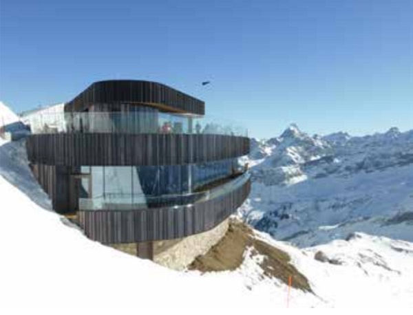
The summit station of the mountain cableway “Nebelhornbahn” is situated next to the town Oberstdorf, Germany at an altitude of 2224 m above sea level. The station was rebuilt in summer and autumn 2016. The building itself is a timber construction with partially curved facades and curved balustrades. The area of the Nebelhorn is famous for skiing in winter and hiking in summer.
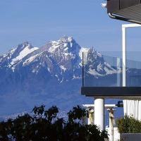
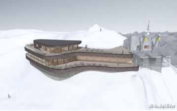
The architect’s plan of Hermann Kaufmann ZT GmbH shows an organic, very transparent shape made of timber, glass and a bronzecoloured cladding, see Figure 1.
4.1 Glass Elements
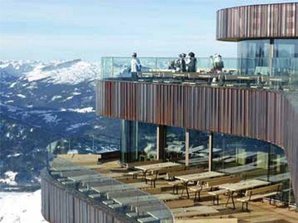
The glass railing is situated on two floors along the terraces of the building, see Figure 2.
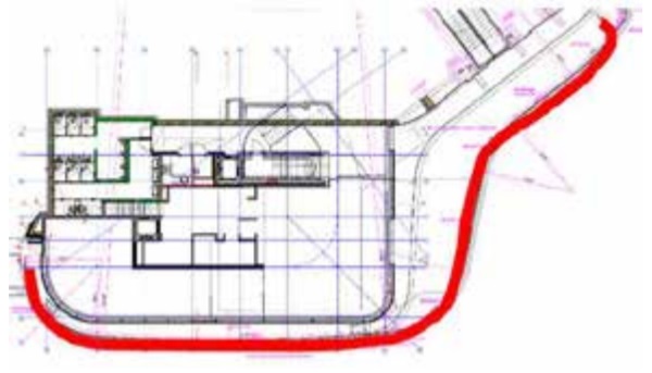
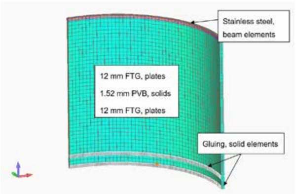
The smallest radius of the balustrade’s curved glass is 870 mm, the maximum radius 6970 mm. A laminated safety glass with two layers of fully tempered glass and a 1.52 mm-thick PVB interlayer was used. At the plane areas laminated safety glass with a 1.52 mm-thick ionoplast interlayer was applied. The clamped glass balustrade is situated on a small base, to protect the glazing at its base, see Figure 3. The overall height of the balustrade of about 1.5 m is higher than building regulations would require. But besides its function as protective barrier it also serves as a wind shield for the visitors of the terrace. The façade consists of fully framed insulated glass units of which some work as sliding doors.
4.2 Structural analysis and impact
4.2.1 Railing
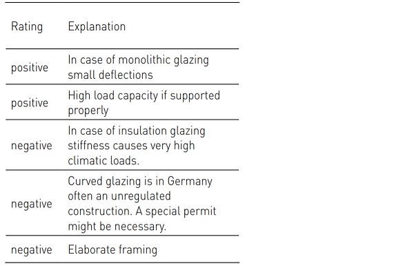
The special feature of this project was the curved glass. There are some advantages but also disadvantages with this kind of glazing, see Table 1.
The wind speed was examined in an expert report with a speed of 50 m/s. The resulting wind loading was 4.7 kN/m².
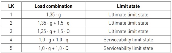
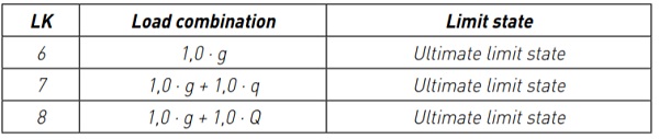
According to Eurocode EN 1990 in combination with DIN 18008-1 the following load sets were considered for the balustrades:
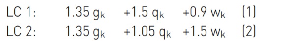
Due to the high wind loads and the low line load’s impact height the load-case LC 2 is dominating.
In addition, it is necessary to consider partial destroyed glass panes as an accidental design situation.
![]()
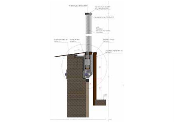
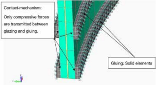
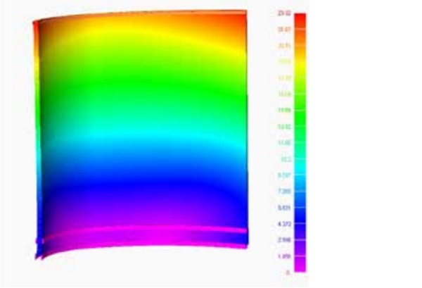
The curvature of the glazing was considered in a finite element analysis, so was the glued constraint situation. The latter is often applied in case of curved balustrades, because otherwise inevitable tolerances of the clamping structure would cause constraint forces in the glass.
Another topic was the anchorage on the wooden substructure. Beside the problems of the analysis it was very important to avoid penetration of snow or rain into the base point of the railing.
4.2.2 Post-breakage behaviour
Beside the load carrying capacity of the intact glazing a remaining load carrying capacity has to be established. It must be ensured that a glass construction cannot collapse (immediately) in case of breakage, so that the safety of pedestrians, e.g. pushing against a glass facade is guaranteed. Depending on the kind of application the verification of residual resistance is done with different testing or numerical methods.
If it is safe to assume that at least one glass layer of the LSG remains intact, because it is protected from all accessible sides, a numerical proof is possible. The reduced loads of LC 3 must be carried by the remaining layer alone. However the edges of the glazing – particularly in the case of balustrades – often are not protected enough against hard impacts. These entire broken elements also must provide a sufficient residual load carrying capacity. As a reliable numerical simulation of broken LSG is not possible (yet), full scale tests and/or expert reports are unavoidable.
The behaviour after breakage of a glass pane depends on many factors. The kind of glass (thermally toughened or heat strengthened glass), the kind of lamination between the glass panes (PVB, ionomer or cast-in-place resin) and the kind of fixture are the main influences.
4.2.3 Impact
Dynamic actions in the form of impact loads have to be considered, too. German standards allow three kinds of verification:
- Comparison to approved systems
- Verification by calculation
- Verification by testing
Curved glazing is excluded from the first two methods. Therefore pendelum tests or at least expert`s surveys have to be charged.
4.2.4 Curved Facade
The resulting pressure in the space between the panes and the mechanical stress to the edge seal is very high.
Under a uniform load bent glass behaves much stiffer than flat glass panes. For the so called “climatic loads” apply almost isochoric conditions (Volume = const.).
According to the DIN 18008-1 [8] it is not allowed to consider a beneficial shear connection in the edge seal. So it is often necessary to consider two cases in the calculation:
- Only radial joint of glass panes (stiff or elastic)
- Additional shear transfer in the edge seal
Aspects like elastic constraint influence of the spacer, consideration of the gluing (intact or with delamination), consideration of the kind of sealing material and many others were very important to investigate. Especially the sealing material plays an important role in the calculation. E.g. a polymer has a nonlinear behavior. The stiffness depends on the geometry, the temperature, the strain-rate and the ageing. The question is, if it is necessary to implement all these phenomena to the calculation.
Because of the extreme difference of air pressure and temperature between production plant and installation site, valves in the space between the panes are necessary during transport to the summit. The manufacturer allowed the valves to be opened for 10 minutes without having severe influence on the gasfilling.
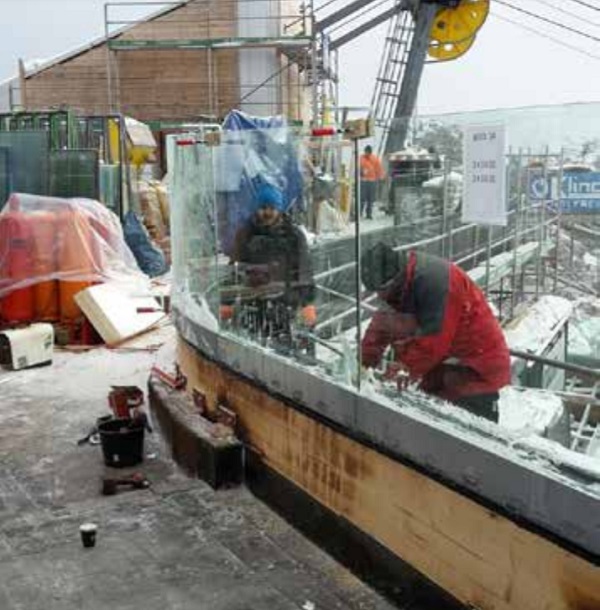
4.2.5 Prefabrication
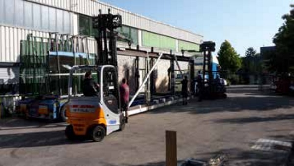
To reduce the time in the cold areas on the top of the mountain as much as possible, time for setup was shifted to the workshop. The elements of glass-plates glued in the substructure were prefabricated (Figure 7). The width of the elements was optimized due to the performance of the helicopter.
4.2.6 Installation
For installation, a very narrow timeslot was given. Reasons are the following:
- Early start of winter with temperatures below zero degree Celsius
- Minimisation of operation breakdowns of the cableway between high season in summer and high season in Winter
- Many project members and trades on a very narrow building site
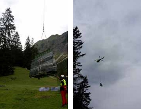
The glass elements were transported to the middle station “Seealpe” by truck, the final step of transportation was done by helicopter (Figure 8). Because of the high cost for the helicopter, it was very important to optimize the size and weight of the prefabricated elements.
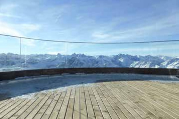
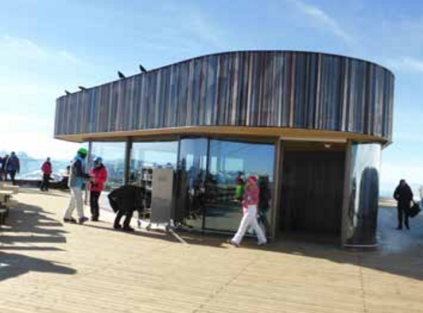
4.2.7 Finished project
The project was finished in time in autumn 2016.
Figure 10 to Figure 13 show the completed project with the railing and the façade.

5 Summit station “Zugspitze”
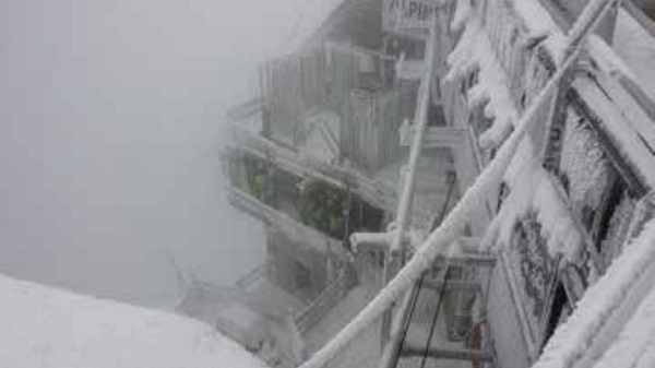
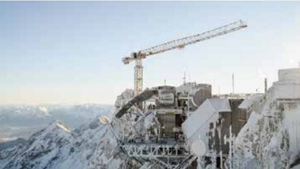
The summit station of the “Zugspitze” is situated near the town GarmischPartenkirchen at 2962 m above sea level. A new cableway including a renovated and partially rebuilt building on the peak is under construction at present. It is the highest situated building site at Germany. The project will be completed in 2017.
5.1 Glass Elements
The façade consists of different glass sizes of double and triple insulated glass units (IGU).
Structural analysis
The wind pressure was examined in an expert report with up to 5.4 kN/m², the snow-load on the terrace is given with 15 kN/m².
For the structural design of IGU, the climatic loads have a main influence. According the DIN standard the following formulas apply accordingly:
Summer :
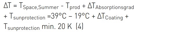
Winter:
![]()
Next step is the approximate calculation of the volumetric coefficient with a linear relationship between variation of volume and load:
![]()
All the formulas for IGU`s can be found in DIN 18008-1 and DIN 18008-2 [2], [3]
Installation
For installation, also a very narrow timeslot was given:
- Early start of winter with temperatures below zero degree Celsius, snowfall also in summer possible.
- Many project members and trades on a very narrow building site
The glass elements were transported to the summit with a second existing cable car from the Austrian side of the mountain.
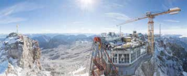
The current situation on the building site at early spring 2017 can be seen in Figure .
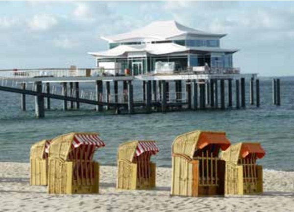
6 The teahouse in the Baltic sea
The Teahouse is situated in the Baltic Sea near the small touristic town Timmendorfer Strand, only accessible over a pedestrian bridge. The impacts of wind and seawater on the building are very high; this had to be taken into account during design of the building and the transparent parts: Large Façade Areas, also with function as anti drop device, accessible glassing – scarcely above the water surface, railings inside and a wind protection outside are all made of glass. The teahouse was designed by Schuberth architects, Hamburg inspired by the Japanese Architecture.
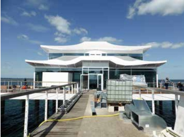
6.1 Facade
The façade is situated in the ground floor and the first floor of the building. The IGU´s are acting as anti drop device and have dimensions of 4630mm x 2730mm. Because of the exposed situation wind zone 3 is obligatory.
The glass set up is from inside to outside:
- A laminated safety glass with two 8mm layers of fully tempered, heat-soaked glass and a 0,76mm-thick PVB interlayer
- 14mm cavity
- 10mm layers of fully tempered, heat-soaked glass
The load carrying posts are shifted to the inside, from the outside only the transparent cover is visible.
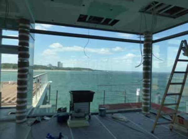
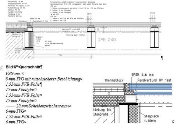
6.2 Accessible glazing
The accessible floor has dimensions of 4760mm x 3300mm in two areas. 10 glass elements with the dimension of 850mm x 1545mm (area 1) and 800mm x 1545mm (area 2) are situated direct above the surface of the water.
Details and the glass set up can be seen in Figure 20.
The analysis was done according DIN 18008 [1]. The ground floor is used as a restaurant, so a load of 5,0 kN/m² and alternately a single point load was considered (Table 2, Table 3).
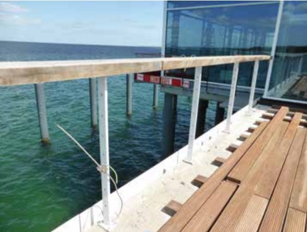
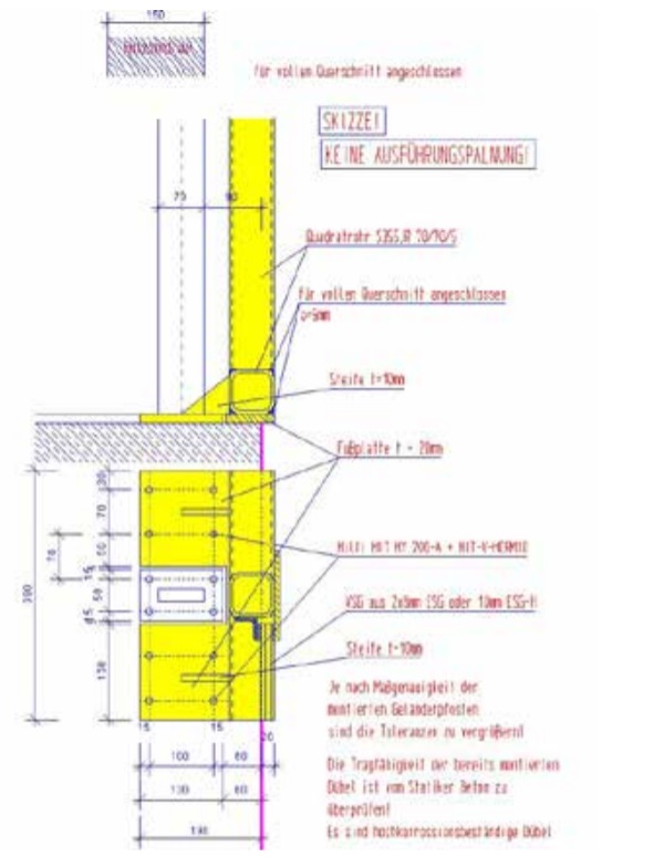
6.3 Windscreen
The additional mounted windscreen with high wind loads up to 2,2 kN/m² has dimensions of 1400mm (width) x 1500mm (height). A laminated safety glass of 2x8mm fully tempered, heat soaked glass was used. Main problem was the mounting with highly corrosion resistive anchoring rods in the bridge to the tea house (figure 21, 22).
7 Conclusions
Constructions at exceptional locations are often challenging but worth one’s while. Extreme boundary conditions and sophisticated demands of the client have to be considered. Experience in the field of structural use of glass, extensive knowledge on the current glazing technologies, state-of-the-art manufacturers and engineering expertise led to the presented impressing solutions.
8 References
[1] ETAG 002: Guideline for European Technical Approval for Structural Sealant Glazing Systems (SSGS)
[2] DIN 18008-1: 2010-12: Glas im Bauwesen – Bemessungs- und Konstruktionsregeln – Teil 1: Begriffe und allgemeine Grundlagen
[3] DIN 18008-2: 2010-12: Glas im Bauwesen – Bemessungs- und Konstruktionsregeln – Teil 2: Linienförmig gelagerte Verglasungen
[4] DIN 18008-2: 2011-04: Glas im Bauwesen - Bemessungs- und Konstruktionsregeln - Teil 2: Linienförmig gelagerte Verglasungen, Berichtigung zu DIN 18008-2: 2010-12
[5] DIN 18008-3: 2013-07:Glas im Bauwesen – Bemessungs- und Konstruktionsregeln – Teil 3: Punktförmig gelagerte Verglasungen
[6] DIN 18008-4: 2013-07:Glas im Bauwesen – Bemessungs- und Konstruktionsregeln – Teil 4: Zusatzanforderungen an absturzsichernde Verglasungen
[7] DIN 18008-5: 2013-07:Glas im Bauwesen – Bemessungs- und Konstruktionsregeln – Teil 5: Zusatzanforderungen an begehbare Verglasungen
[8] Herrmann, T.; Siebert, B.: Energetische Sanierung Hypo-Hochhaus – Gebogene 3-fach Isolierverglasung der neuen Doppelfassade. Stahlbau Sonderheft Glasbau April 2014, Ernst & Sohn Verlag Berlin
[9] Siebert, B., Herrmann, T.: Glass balustrades and facades on pedestrian bridges, 9th German - Japanese Bridge Symposium in Kyoto. September 2012 in Kyoto
[10] Feldmeier, F.: Bemessung von DreifachIsolierglas. In: Stahlbau Spezial 2011 – Glasbau. Ernst & Sohn, Berlin 2011.
[11] Siebert, B., Pistora A. Teehaus am Timmendorfer Strand. Glasbau 2015. Ernst und Sohn Verlag
9 Acknowledgements
We would like to thank the company StahlGlasbau Dann GmbH (www.dann-gmbh.de) for providing the pictures of the installation.