Ennio Mognato, Alessandra Barbieri, Piero Quaia, Robert Miklus, Danijel Hatezic
Introduction
The compatibility of two or more materials consists in their capacity to co-exist in juxtaposition for an indeterminate period of time without manifesting signs of detachment (delamination), discoloration or alterations produced by chemical interactions. In general, the individual material is stable when isolated; upon entering into interaction with another material - even due to the effect of external agents like humidity, elevated temperatures or irradiation - it can become instable and give rise to incompatibility phenomena.
In the specific case of laminated glass for building applications, these phenomena generally occur between sealant materials and interlayer, but they can also be due to interaction between other organic materials such as those used for gaskets, cleaning etc.
Generally a laminated glass pane should be produced following a controlled process to be free of defects, or to avoid the risk of their appearance in the future, having attention to the following aspects:
- glass preparation (storage, cutting, washing, drying temperature);
- interlayer preparation (storage, stretchingcutting, etc.);
- laminating process (assembly glass + interlayer, de-airing, autoclaving or heating).
The onset of delamination phenomena and the occurrence of bubbles in a laminated glass pane, in general, can be due also to the combination with other ones such as the not well-fit assembly of glass panes, excessive moisture content of the interlayer, stagnation of water, contamination by dust or oils, thinning of the PVB.
A manufacturing process not properly done or un-correct choice, composition and installation of the component can affect the durability of the product. The contamination phenomena are aspects that may affect the performance of the product, but certainly involve visual defects not always tolerable, especially when the glazing is not inserted in a support frame.
Manufacturers of sealants provide a “check list” of products compatible with their sealants in order to avoid incompatibility. In general it is good practice to check the compatibility of small scale samples in advance, subject to cycles of accelerated aging.
Several authors have conducted experimental research on the durability of laminated glass by analysing in detail the various factors that affect the mechanical performance, such as adhesion [1] and rising of defects as bubbles, delaminations and opacity [2, 3]. With regard to the specific problem of the interaction between interlayer and sealants, only two published studies should be mentioned.
In the first paper [4] the authors provide data on the edge delamination phenomenon of laminated glass with PVB, analysing some case studies: the Sidney Opera House (Australia) and Terminal 2 Changi in Singapore (Rep. of Singapore). The research has produced a series of data on samples made with two types of interlayer (PVB and SGP) and glass (annealed and thermally toughened) with silicone sealing.
The samples exposition was done in natural environment (Hileah Florida) for 54 months. A similar study was later developed by Block and Davis [5] on ionomer interlayer (SGP) in samples exposed to natural environment in Florida for 7 years and in combination with different sealants for 42 months, in addition to the analysis of two case studies in which the glass panes were laminated with SGP. In both studies, a coefficient called ESN (Edge Stability Number) was defined as indicator of the presence and extent of defects.
In 2005, a working group was created by stakeholders, coordinated by IFT Rosenheim in order to define a protocol of test procedures which verify:
- The Usability of sealants (Part 1): testing of materials in contact with the edge-sealing of insulating glass units;
- The Usability of sealants (Part 2): test of materials in contact with edge of laminated glass and laminated safety glass.
The Part 2 was assumed as reference for the execution of the following tests, object of the present study. The defects, sign of contamination, cited in the IFT protocol are classified in the following categories:
- bubbles (size/diameter, total number, maximum and average penetration depth)
- discoloration
- delamination
defects partially covered by EN ISO 12543-4, which cites “The changes in properties are judged by the occurrence of bubbles, delamination, and cloudiness (not discoloration)”.
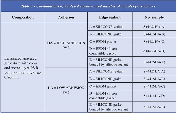
Samples manufacturing
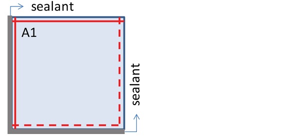
The samples tested have square shape of 300 mm x 300 mm, obtained by original laminated glass pane of dimensions 600 mm x 600 mm, which glass edges were firstly smooth ground worked. Therefore the edges of original panes are worked before the laminating process and they are classified as “pre-lamination finishing” (red line in figure 1). The laminating process was carried out with the same procedure for the whole samples using the same type of interlayer (mono-layer), produced by the same company, with two different adhesion degree: low (signed LA) and high (signed HA).
Four samples were done from these laminated glass panes, to which the sealant materials were applied with the five configuration defined in the following. The samples obtained by cutting the laminated glass pane with “pre-lamination finishing” have two neighboring edges that are then smooth ground worked. In this way the same sample 300 mm x 300 mm has two contiguous edges ascribed to the category of “post-lamination finishing” edges (dotted red line in figure 1)
The samples obtained by the cutting of the “prelaminating finishing” panes were afterwards handled with the sealant systems defined in the third column of table 1 (figure 2).
The samples were called by a alphabetic/numerical code defined by:
- composition(44.2);
- adhesion (HA for high adhesion or LA for low adhesion);
- edge sealant (A for type A; B for type B; C for type C; D for type D; E for type E) (see Table 1); as reported in the fourth column of table 1.
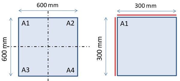
(red line: “pre-lamination finishing” edge; dotted red line: “post-lamination finishing” edge)
Preliminary tests on laminated glass panes
In order to verify if the thermal cycles may cause the onset of bubbles regardless of the treatments of the edges, high temperature tests were carried out on some samples without sealant, specifically on two samples for each type of adhesion (high and low) according to the following thermal cycles:
a. no. 2 samples with high adhesion PVB and no. 2 samples with low adhesion of PVB tested for 16 h at 100°C, and next visual inspection at 23°C;
b. no. 2 samples with high adhesion PVB and no. 2 samples with low adhesion of PVB tested:
1. 2 h at 100°C, and next visual inspection at 23°C;
2. 2 h at 120°C, and next visual inspection at 23°C;
3. 8 h at 120°C, and next visual inspection at 23°C.
The samples tested according to the above procedure did not showed defect, as indicated in the reference standard EN ISO 12543-4; even along the edges of the plates, independently from their working process.
High temperature test
This test is aimed to verify the compatibility between interlayer and sealant under boundary conditions, without UV radiation exposition. The applied procedure is that one described in IFT protocol. The test procedure provides the following phases carried on 4 samples for each typology, of which 3 samples (from n° 1 to n° 3) are subjected to aging process, whereas the sample n° 4 is assumed as witness sample:
1. conditioning at controlled environment (23°C and 50% U.R.) for 7 days;
2. samples inspection to verify the presence of defects as bubbles or delamination;
3. draw up of some samples with thermocouple of type K which precision is ±0,1 °C (on an amount of 30 samples, 3 samples were drawn up and placed at different positions in the testing climate chamber);
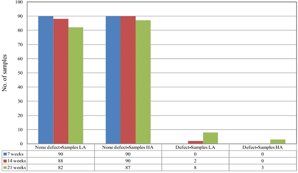
4. storage of samples in the climate chamber at controlled temperature, fixed at 60°C for 21 weeks with check time step of 7 weeks, recording daily the temperature of the climate chamber and glass pane samples.
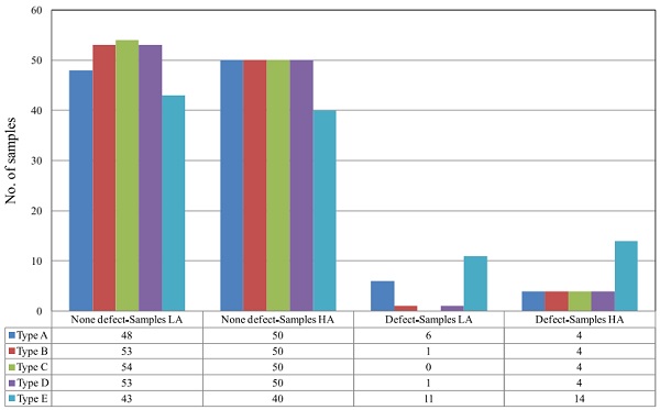
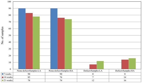
The sampling type E - both with high adhesion PVB both low adhesion one - was come out that it was more vulnerable than the others to high temperature test. It has been observed the occurrence of bubbles of small size near the edges of the panes, without distinction on the type of interlayer adhesion. In figures 3 and 4 the results of high temperature test are plotted versus sealant typology and testing time.
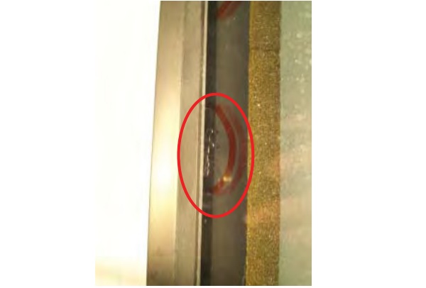
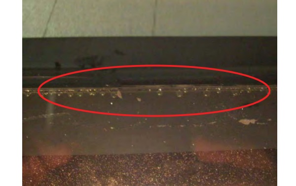
In sample 44.2-HA-E/01, no. 7 bubbles were recorded with penetration depth of 0,5 ÷ 1,17 mm and diameter of about 0,6 ÷ 2,70 mm (Figure 5a); whereas in samples 44.2-HA-E/02 and 44.2-HA-E/03 some very small bubbles were recorded along the edge (Figure 5b). The defects were evinced after 21 weeks of aging and they were on the pre-lamination finishing, along the adhesion side of bonded gasket.
Defect detection (Yes/No) versus sealing typology and PVB adhesion
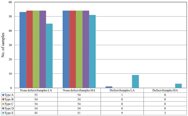
Defect detection (Yes/No) versus testing time and PVB adhesion
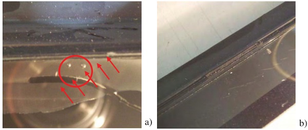
a) bubbles in sample 44.2-HA-E/01; b) bubbles in sample 44.2-HA-E/03
In sample 44.2-LA-E/01 the bubbles appeared just after 14 weeks along pre-lamination finishing and also post-lamination finishing. The bubble depth was about 1,34 mm (pre-lamination finishing) and 1,54 mm (post-lamination finishing) with diameter of 0,82÷2,16 mm and 0,01÷1,56 mm respectively.
After further 7 weeks of ageing, the phenomenon increased: a) on the pre-lamination finishing side some small bubbles were recorded with diameter of 0,1 mm along the edge and no 3 bubbles which diameter was about 1,18÷2,21 mm; b) on the postlamination finishing side new no. 4 bubbles were recorded which diameter was 0,50÷3,48 mm and depth from the edge 1,11÷1,56 mm.
In sample 44.2-LA-E/02 some small bubbles were recorded and no 2 bubbles well-distinguished with 1 mm diameter, as a delamination phenomenon which depth was 1,24÷1,93 mm and 3,83 mm extended, along the pre-lamination finishing; along the postlamination finishing no. 2 bubbles were recorded with a diameter of 0,5÷1,4 mm and analogous delamination effect with depth of 0,20÷1,46 mm and extension of 6,16 mm.
In sample 44.2-LA-E/03, no. 1 bubble was recorded with a diameter of 0,5 mm together with a limited delamination phenomenon which depth was 0,5÷0,75 mm and extension of 1,5÷7,00 mm (Figure 6). The defects were evinced after 21 weeks and only on the post-lamination finishing.
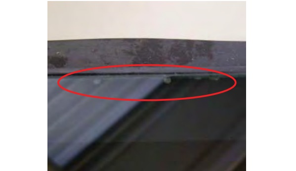
bubbles in sample 44.2-LA-E/03
High humidity and UV irradiation test
This test is aimed to verify the compatibility between interlayer and sealant under boundary conditions by which the environmental conditions are simulated.
The applied procedure is that one described in IFT protocol.
The test procedure provides the following phases carried on 4 samples for each typology, of which 3 samples (from n° 5 to n° 7) are subjected to aging process, whereas the sample n° 8 is assumed as witness sample:
1. conditioning at controlled environment (23°C and 50% U.R.) for 7 days;
2. samples inspection to verify the presence of defects as bubbles or delamination;
3. draw up of some samples with thermocouple of type K which precision is ±0,1 °C (on an amount of 30 samples, 3 samples were drawn up and placed at different positions in the testing climate chamber);
4. storage of samples in climate chamber at controlled temperature, fixed at 58°C and humidity > 95% for 7 weeks with inspection at the end of 7th week;
5. placing of samples on steel frame for UV irradiation test (14 weeks long), following the EN ISO 12543-4:2000, recording daily the temperature and irradiation intensity on drawn up specimens.
In figures 7 and 8 the results of high temperature test are plotted versus sealant typology and testing time.
Defect detection (Yes/No) versus sealing typology and PVB adhesion
Defect detection (Yes/No) versus testing time and PVB adhesion
The samples did not evinced defects after 7 weeks in climate chamber.
In sampling type A, the following aspects were observed after the UV irradiation:
- sample 44.2-HA-A/05: some small bubbles along the pre-lamination fi nishing for an extension of 131,15 mm with a diameter about 0,10 mm; during the next 7 weeks, a new bubble with diameter of 1,56 mm along the pre-lamination fi nishing and one with diameter of 1,16 mm along the post-lamination finishing;
- sample 44.2-HA-A/06: a bubble with diameter of 1,35 mm appeared along the pre-lamination finishing, after 14 weeks of UV irradiation;
- sample 44.2-LA-A/05: along the post-lamination finishing, a bubble with a penetration depth of 1,33 mm and a diameter of 1,34 mm, that increased up to 1,65 mm;
- sample 44.2-LA-A/07: along the pre-lamination finishing, a bubble with a penetration depth of 0,91 mm and diameter of 1,00 mm and delamination along the post-lamination fi nishing for a depth of 1,14÷1,28 mm with an extension of 3,15÷11,83 mm; after 7 weeks the defects increased lightly in dimension and extension.
In sampling type B, the following aspects were observed after the UV irradiation:
- sample 44.2-HA-B/06: during the first cycle (7 weeks) some small bubble along the pre-lamination finishing for an extension of 27,11 mm with diameter about 0,1÷1,35 mm; no more defect were evinced during the further 7 weeks of irradiation.
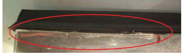
- sample 44.2-HA-B/07: delamination phenomenon along the post-lamination finishing with a depth of 2,36 mm and an extension of 68,36 mm (figure 9); after further 7 weeks of UV a small defect increasing was observed (depth up to 3,31 mm and extension up to 69,28 mm);
- sample 44.2-LA-B-06: a single bubble along the pre-lamination finishing with diameter of 1,39 mm.
In sampling type C, the following aspects were observed after the UV irradiation:
- sample 44.2-HA-C/06: some small bubbles along pre-lamination finishing with a depth of 0,05 mm and an extension of 28,32÷68,20 mm; the mean value of diameter was 0,1 mm; after further 7 weeks the extension the defect increased up to 84,46 mm;
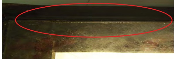
- sample 44.2-HA-C/07: a delamination phenomenon along the pre-lamination finishing with a depth of 1,57÷3,09 mm, for an extension of 12,51÷14,71 mm (Figure 10); after further 7 weeks the extension increased up to 13,07 mm, with an increment of depth 1,73÷3,20 mm.
In sampling type D, the following aspects were observed after the UV irradiation:
- sample 44.2-HA-D/07: some small bubbles along the pre-lamination fi nishing with a depth of 0,5 mm and an extension of 9,28 mm; the mean value of diameter was 1 mm; after further 7 weeks the defects increased by increment of diameter up to 1,0 mm and of extension up to 11,56 mm, along the pre-lamination fi nishing; the post-lamination finishing evinced delamination phenomena after the first 7 weeks with an extension of 12,40 mm and a depth of 1,02 mm which increased after the next weeks (depth of 1,75 mm and extension of 12,42 mm);
- sample 44.2-LA-D/06: after 14 weeks of UV irradiation, no. 3 bubbles appeared with a diameter of 0,68÷1,37 mm.
In sampling type E, the following aspects were observed after the UV irradiation:
- sample 44.2-HA-E/05: small bubbles along the pre- and post-lamination finishing with a mean diameter of 1,65 mm; these defects were stable after further 7 weeks of UV aging;
- sample 44.2-HA-E/06: small bubbles along the pre- and post-lamination finishing with a mean diameter of 1,6 mm and a delamination defect near the corner of post-lamination finishing; after further 7 weeks of UV aging, the delamination increased up to a depth of 1,39 ÷ 7.37 mm;
- sample 44.2-HA-E/07: small bubbles along the pre- and post-lamination finishing with a mean diameter of 1,6 mm; these defects increased lightly after further 7 weeks of UV aging;
- sample 44.2-LA-E/05: small bubbles along the pre- and post-lamination finishing with a mean diameter of 0,1 mm (Figure 11) and a delamination defect near the corner of post-lamination finishing with a depth of 1,50 ÷ 3,61 mm and extension of 62,5 mm (Figure 12); these defects increased lightly after further 7 weeks of UV aging;
- sample 44.2-LA-E/06: small bubbles along the pre-lamination finishing with a mean diameter of 0,1 mm; these defects were stable after further 7 weeks of UV aging but no. 25 bubbles appeared on the post-lamination finishing with diameter of 0,5 ÷ 0,71 mm;
- sample 44.2-LA-E/07: small bubbles along the pre-lamination finishing with a mean diameter of 0,1 mm and no. 2 bubbles on the post-lamination finishing with diameter of 1 mm.
Further tests to increase the defects arising
Later on, in the next stage of study, the sample used to carry out high temperature test were used for carrying on the following tests done in sequence:
1) temperature cycles of 24 h from -5 °C to +80°C with slopes of 21,25 °C/h for 28 days.
2) test of immersion in water, at room temperature, for 28 days.
3) application of a acetic silicone on half of each sealed side followed, after silicone reticulation, by high temperature test (60 ° C) for 14 days; then, on the same samples, high humidity test in climate chamber for 14 days; finally UV radiation test for 14 days, for a total duration of 42 days.
The tests referred to points 1), 2) e 3) did not evinced the presence of new defect and that recorded in the previous test were stable. There was only one case in which further defects arose: sample 44.2-LAE/03 in which, at the end of the high humidity test at point 3), a delamination phenomenon appeared along post-lamination finishing, where acetic silicone had not been applied (Figure 13).
Conclusions
The high temperature test at 60°C for 21 weeks, with check step of 7 weeks, did not induce the arising of defects on tested samples except of the sampling type E, in which the silicone gasket was bonded by neutral silicone along the laminated glass pane.
Bubbles were recorded in this sampling (E) along the pre-lamination finishing on 5 sample to 6, during the cycle between the 14th and 21st week; the same phenomenon was recorded only on 2 samples along the post-lamination finishing. The delamination was recorded only on 1 sample (44.2-LA-E-02).
The combined test of high humidity (at 58°C and 95% H.R. for 7 weeks) and subsequent UV irradiation (following ISO EN 12543-4 for 14 weeks) induced the arising of defects -mainly bubbles- starting from the irradiation phase in almost all types of samples, with a number of samples greater in the case of pre-lamination fi nishing (14 samples). Moderated delamination phenomena were recorded more frequently on the post-lamination fi nishing (5 sample). The sampling with more presence of defects has been that of type E.
In this sample (E), the predominant defect was the occurrence of bubbles, with modest size, regardless of the type of edge finishing; delamination has been recorded only in 2 samples, one LA (low adhesion) and one HA (high adhesion). In general the onset of defects occurred at the end of 14th week.
The additional testing conducted on samples, previously tested at high temperature for 21 weeks, did not evidence the onset of additional defects, compared to those already present or their extension, in the sides of acetic silicone application.
The edge finish type E appears to be relatively critical with respect to the occurrence of defects such as bubbles and delamination. However the defect extension is restricted to the sample edges. The technical solution with silicone gasket bonded by silicone sealant may to be not the best one for specific environmental application.
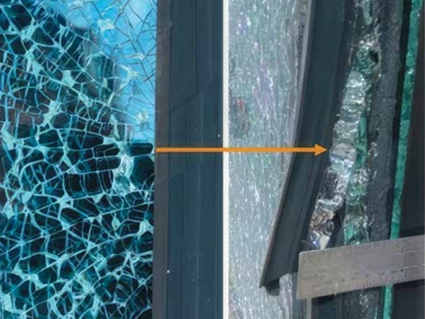
It was never detected in the tested glass following the exposed procedures an evident and clear phenomenon of interlayer contamination, similar to what is sometimes found in some applications on glazing facades (Figure 14), or other types of application.
In the case we have investigated it was not noted a deeply contamination phenomenon as some time occurs in situ. It can depend from a good quality of material and lamination process as well the kind of ageing used. It means that when delamination by contamination happens probably some process faults had occurred or humidity and sealant materials work on the edge.
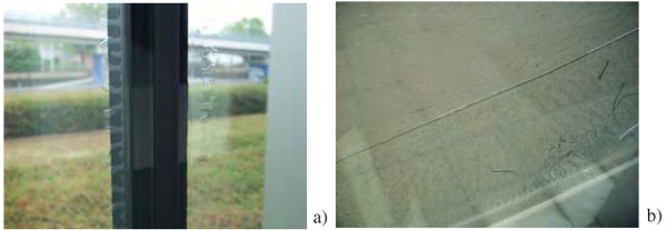
a) defect starting from the glass pane edge;
b) defect starting from a bubble
Acknowledgments
The technicians of SSV - SVP Laboratory, Mr. G. Negri and Mr. F. Comiati, are acknowledged for the collaboration to the execution of experimental tests in our Laboratory, as the production staff of Permasteelisa Group.
References
[1] Keller U., Mortelmans H., Adhesion in Laminated Safety Glass - What makes it work?, Glass Processing Days, 1999, pp. 353-356.
[2] Wong B.C., Shattering old myths about defect formation in laminated glass, Glass Processing Days, 1997, pp. 464-469.
[3] De Jackome G.E., Moisture induced delaminations in automotive windscreens, Glass Processing Days, 1997, pp. 486-490.
[4] Davis P., Cadwallader R., Delamination Issues with Laminated Glass - Causes and prevention, Glass Processing Days, 2003, pp. 427-430.
[5] Block V., Davis P.S., Enhanced Edge Stability with Structural Glass laminates, Glass Processing Days, 2005, pp. 1-2.
Authors
Ennio Mognato, Alessandra Barbieri
Stazione Sperimentale del Vetro
Piero Quaia
Permasteelisa Group
Robert Miklus, Danijel Hatezic
Formator Safety Glass.d.o.o.