Article Information
- Digital Object Identifier (DOI): 10.47982/cgc.8.416
- This article is part of the Challenging Glass Conference Proceedings, Volume 8, 2022, Belis, Bos & Louter (Eds.)
- Published by Challenging Glass, on behalf of the author(s), at Stichting OpenAccess Platforms
- This article is licensed under a Creative Commons Attribution 4.0 International License (CC BY 4.0)
- Copyright © 2022 with the author(s)
Authors:
- Maria Dimas - Eckersley O'Callaghan Ltd
- Faidra Oikonomopoulou - TU Delft Faculty of Architecture and the Built Environment
- Marcel Bilow - TU Delft Faculty of Architecture and the Built Environment

Abstract
Interlocking cast glass assemblies are a promising solution for architectural cast-glass applicationsaiming for high transparency and a reversible structure that allows the reuse of the glass components (Oikonomopoulou et al.,2018; Oikonomopoulou,2019b). In such a system, an interlayer material between the glass elements is essential, to assist the homogenous stress distribution and account for the surface microasperities of the glass elements. Towards circularity, this material should be dry (and not an adhesive), allowing for the eventual disassembly of the system. Previous experimental work by (Aurik at al.,2018; Oikonomopoulou at al.,2019b) has focused on the use of PU and PVC interlayers as suitable candidates; the focus in those studies has been solely placed on the mechanical performance of the interlayer material.
This research provides a review of potential material candidates suitable for interlayers of an interlocking cast glass assembly based on a set of revised design and performance criteria that are divided into primary and secondary. Furthermore, the impact their unique material properties have on the potential application of the interlocking system is examined. The whole process, from fabrication to construction of the entire assembly, based on an assumed building scenario, ispresented in a chain reaction manner, whose starting point is the interlayer itself.
After defining the design criteria the interlayer should adhere to, the proposed candidates are: PETG sheets (Vivak®), Neoprene, Aluminum, Laminated Polyurethane (PU) and a Soft-core aluminum interlayer. The unique properties and fabrication challenges of all five proposed interlayers are considered, as well as their properties in relation to assembly, which leads to the development of two distinct assembly sequences. The main distinction concerns the interlayers that risk creeping and those that do not. The research concludes with a comparison between the interlocking assembly and the other glass block assemblies currently applied.
1. Introduction
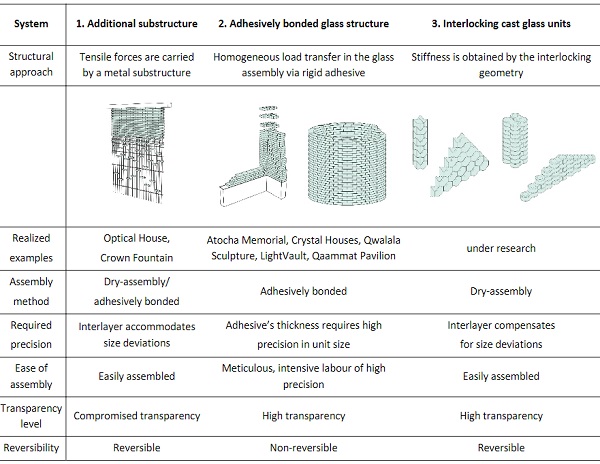
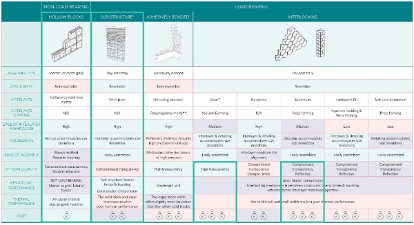
The architectural application of cast glass blocks is slowly gaining popularity, with recent examples including the Qaammat pavilion (Oikonomopoulou et al., 2022), the LightVault (Parascho et al., 2020), the Qwalala Sculpture (Paech, Goppert, 2018), the Crystal Houses (Oikonomopoulou et al., 2018), the Optical house (Oshima, 2012), the Crown Fountain (Hannah,2009), and the Atocha memorial (Paech, Goppert, 2008). All aforementioned projects of self-supporting cast glass block assemblies rely either on a visible, supportive sub-structure (e.g. in Optical Houses, Crown Fountain) or, for a less visuallyintrusive system, on a clear or light-coloured adhesive for bonding the solid glass blocks together (e.g. in Atocha Memorial, Crystal Houses, Qwalala, LightVault and Qaammat Pavilion), as shown in Fig. 1 and Table 1.
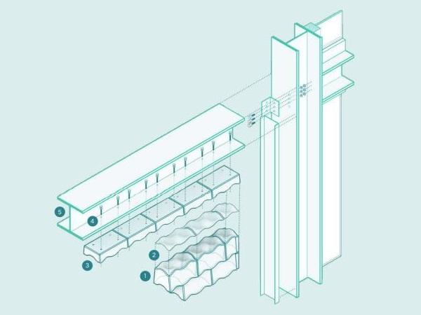
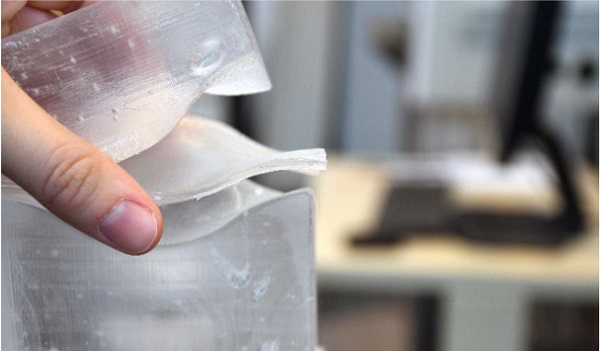
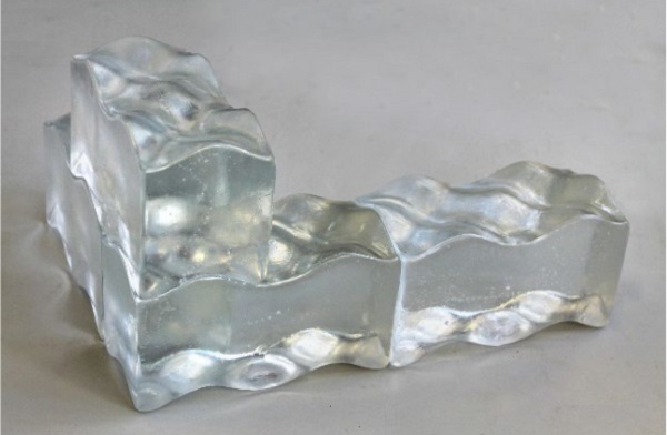
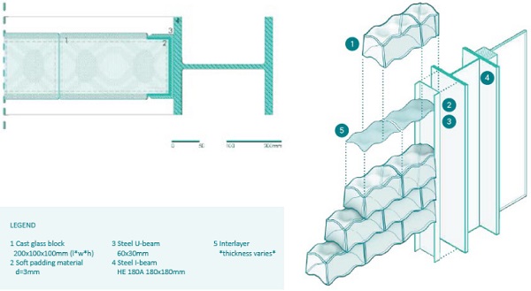
The option of adhesive bonding is gaining increasing popularity, as it offers a comparatively higher level of transparency, whilst ensuring the structural integrity of the assembly. Nonetheless, the use of adhesive yields a non-reversible structure and further hinders the recyclability of the glass components due to contamination. In an effort towards a reversible and demountable cast glass block assembly, which simultaneously offers a competitive level of transparency, a novel system employing interlocking cast glass blocks has been introduced by (Oikonomopoulou et al., 2018) (Fig. 1, right). The system, which is still under development, features a dry-stack assembly, with interlocking cast glass blocks and an intermediate interlayer material (Fig.2) that evenly distributes the stresses and accommodates the size deviations of the individual blocks. Table 1 summarizes the main characteristics of the three systems.
While there has been development and experimental testing, towards optimizing the interlocking glass block geometry itself (Jacobs, 2017; Yang, 2019; Oikonomopoulou, 2019a), a consistent study on the interlayer material has not yet been carried out. Instead, limited experimental data is available from previous studies (Aurik, 2017; Oikonomopoulou, 2019a; Akerboom, 2016; Oikonomopoulou 2019b) which focus primarily on the creep performance of the chosen interlayer, rather than on all interwoven aspects related to the eventual applicability and assembly of the cast glass structure.
This study therefore aims to set design and performance criteria for such interlayers and explore potential interlayer material candidates in terms of mechanical performance and manufacturability to the desired interlocking shape. Furthermore, the extent to which the interlayer material affects the detailing and assembly of the interlocking cast glass block structure is examined. The study results in a roadmap that may assist with the selection of the most suitable interlayer material, depending on the respective design criteria of future designs.
Table 1: Design principles of the different structural systems employing cast glass components derived from (Oikonomopoulou, 2019b)
2. Methodology
The research begins with a brief review of relevant studies, to determine the design and performance criteria for the interlayer material selection. A material study follows, in which various promising interlayer candidates are specified based on the set criteria and properties, as verified by CES Edupacksoftware and relevant literature sources. Apart from the material properties and performance, the fabrication methods and challenges for each interlayer candidate are examined. Having defined the proposed interlayers, the assembly and detailing of the interlocking cast glass block structure is presented, based on an assumed building scenario utilizing a peripheral metal frame.
The interlocking cast glass block employed, is largely based on the studies of (Jacobs,2017; Yang, 2019; Oikonomopoulou, 2019b), and is shaped as showed in Fig. 3 below, developed by (Jacobs,2017). The different detailing and construction requirements occurring depending on the interlayer material selection are examined. The findings of the study are summarized in a roadmap, where depending on the unique requirements or priorities of a project, the relevant interlayer and key considerations can be identified. Lastly, potential aspects for development of the research are presented.
3. Review of previous dry-interlayer studies for cast glass block assemblies
For the investigation of an interlayer material for cast glass blocks, previous studies developed a set of design criteria, while considering materials compatible with glass. Indeed, the previous studies presented below focus greatly on Polymers, which are commonly combined with glass. Polymers are typically used as interlayers in laminated float glass panes, where they are mainly subject to dynamic or cyclic loads (wind, hard body impact etc.) for their shear strength capacity. However, Polymers are also known to present satisfactory compressive strength. Considering the interlayer of the interlocking glass block assembly would be mainly subject to a uniaxial compressive load, Polymers could indeed present potential for this assembly.
Studies involving an experimental investigation of interlayer materials for cast glass blocks include (i) a stacked glass block column (Akerboom, 2016), (ii) a glass block masonry bridge (Aurik, 2017) and (iii)experiments on glass interlocking blocks (Oikonomopoulou, 2019b). Table 2 presents the design criteria of the interlayers within each project and their performance.
Table 2: Design criteria and selected interlayer materials in previous case-studies.
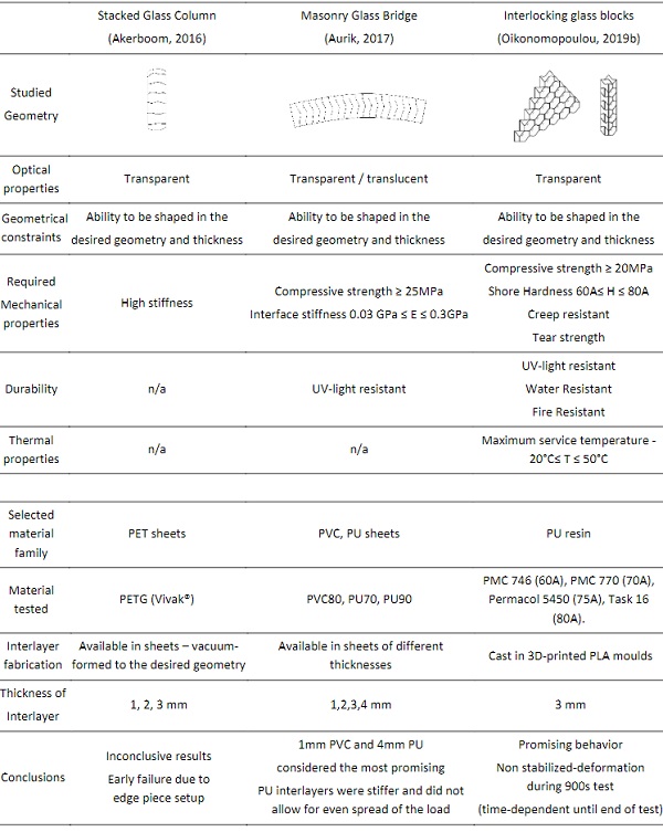
All three studies set transparency-translucency as a main criterion which, in combination with the stiffness criteria, limited the material selection towards polyurethanes (PU) and Polyvinyl Chloride(PVC). The compressive strength of the interlayer is considered from the same source (Oikonomopoulou et al., 2014) as a representative number, however, in practice, this value is highly dependent on each unique case study- for example, taller assemblies will result in higher loads. For the durability and thermal properties, limits commonly required in architectural applications are stated, which are less likely to have greatly affected the material selection.
The required stiffness of the interlayer presented the most variations among the studies. In study (i) (Akerboom, 2016) argues that the stiffness should be relatively high in order to avoid creep. Unfortunately, the single experiment conducted failed prematurely, due to the edge piece setup, so the results in regard to PETG sheets (Vivak®) are inconclusive. In case (ii) the interlayer material is chosen to have a significantly lower stiffness than the glass (Aurik, 2017). Sheet specimens of various thicknesses (1-4 mm) were tested, concluding that the 1mm PVC and 4mm PU were the most promising. The same study indicated that the thicker interlayer variants (3-4 mm) allow for a more homogeneous distribution of the stresses and of an increased stiffness of the interlayer.
For PVCthough, 3-4 mm thick interlayers visibly creeped during testing. Instead, thinner PVC interlayers were chosen, after it was experimentally proven that the material was highly time-dependent and creep occurred under static loads. Finally, in study (iii) the interlayer should be stiff enough to avoid penetration, yet flexible enough to allow for adapting to the micro-asperities of the glass components(Oikonomopoulou, 2019b). Four different interlayer materials with a Shore Hardness between 60-80A were tested: PMC 746 (60A), PMC 770 (70A), Permacol 5450 (75A) and Task 16 (80A).
All alternatives could be cast into the desired interlayer geometry (Fig.2). Some of the specimens tested presented promising behavior, though did not stabilize within the test duration of 900s, indicating that creep performance of the chosen interlayers needed further experimental investigation. The results also suggested that the tear strength of the interlayer is as important as its Shore Hardness. In particular, the assemblies interleaved with Permacol 5450 (75A) and PMC 746 (60A) failed due to the early tearing of the interlayer which lead to glass-to-glass contact and thus, failure due to peak local stresses.
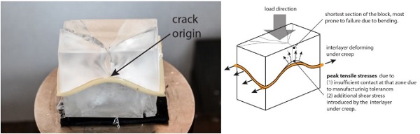
Where 3mm thick interlayers of Task 16 (80A) and PMC 770 (70A) were used, it was noticed that insufficient or non-homogenous contact of the interlayer with the glass blocks due to dimensional deviations of the cast components or/and insufficient thickness of the interlayer, can lead to the eventual failure of the glass block assembly even under static load due to the occurrence of peak stresses, further increased by lateral forces imposed by the creep of the interlayer (Oikonomopoulou, 2019b), as shown in Fig. 4.
Another observation regards the different manufacturing method of the interlayer in each case-study in respect to the desired geometry. The single-curved interlocking geometry of example (ii) allowed for the use of readily available PU and PVC sheets in various thicknesses. Instead, the double-curved interlocking geometry of examples (i) and (iii) lead to the selection of either a sheet that can be vacuum-formed to the desired geometry or of a PU interlayer that can be cast in the desired form.
4. Design and performance criteria for the interlayer material
The previously discussed studies focused on establishing criteria that lead to customized interlayer solutions for respective designs. Aim of this work is to provide an overview of possible interlayer materials based on a more extensive set of design and performance criteria, as well as ease-of -manufacturing and constructability. The goal is to provide architects and structural engineers with a material selection roadmap for the interlayer material based on the prioritized criteria of the designed interlocking glass structure. Hence, having examined previous design criteria for the interlayer material, a set of new revised criteria can be determined.
To ensure the research will not be prematurely limited, the criteria are divided into primary and secondary. The research will focus on finding materials that fulfill the primary criteria, which are considered essential for the proper structural function of the interlayer and the interlocking assembly. The secondary criteria concern aspects that do not interfere with the structural integrity of the assembly and therefore will be examined with more flexibility. The established criteria are summarized in Table 3. Highlighted in bold are the criteria that have changed or become more dominant compared to the previous studies.
Table 3: Revised design criteria for interlayer material
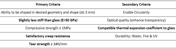
4.1. Primary
- Ability to be shaped in desired geometry and thickness (≤2-3 mm)
The geometrical constraints defined by the previous studies have remained unchanged in this research. The interlayer material should be able to be processed in the decided upon geometry and thickness. The interlayer shall accommodate the size discrepancies of the individual blocks and achieve a homogeneous contact, to prevent the occurrence of localized peak stresses, which can lead to failureof the assembly (Oikonomopoulou, 2018). The ability of the interlayer to accommodate the size deviations of the individual blocks further contributes to decreasing the costs of a cast-glass structure, as it evades the post-processing of the blocks, such as in the Crystal Houses facade (Oikonomopoulou et al., 2017). Previous realized examples suggest anticipated size deviations in height and flatness of ±1 mm for (mould-pressed) borosilicate glass blocks (Paech, Göppert, 2008) and of ± 1.5 mm for (open-mould) soda-lime cast glass blocks (Oikonomopoulou et al., 2022) of a size comparable to terracotta bricks. Thus, a thickness between 2-3 mm seems to be an optimum for allowing a consistent contact area while being able to absorb surface irregularities.
- Slightly less stiff than glass (E<50GPa)
An interlayer between two interlocking objects of a brittle material, should be more ductile than the material itself. However, if the interlayer is considerably less stiff than the interlocking components, it is expected to creep; moreover, it can greatly compromise the composite stiffness of the assembly. To avoid such an adverse outcome, the interlayer is proposed to have a lower, but comparable stiffness to the cast glass. It should be soft enough to achieve a homogeneous contact area with glass, yet it should not risk the system’s stability. A similar proposition had been made by (Wurm & Peat, 2007): “The hardness, stiffness and durability of the interlayer affect the assembly’s system under loading. The load transfer layer should combine a modulus of elasticity similar to that of glass and a compressive strength as high as possible.” According to CES EduPack 2019 (Granta Design Limited 2019), borosilicate and soda-lime glass have a Young’s Modulus ranging from 50- 72GPa. Depending on the interlayer material, instead of the Young’s Modulus, the shore hardness may be more relevant to consider, as has been seen in the previous studies of Section 3.2.
- Compressive strength≥ 2MPa
The minimum compressive strength of the interlayer is stated at a representative value, relevant to the expected maximum compressive load (e.g. due to own weight) of relevant realized examples. Based on previous realized examples, owing to the large thickness and thus contact area between the blocks, the anticipated permanent compressive stresses acting on a glass-block structure due to own weight are typically considerably less than 0.5 MPa. For example, at the lowest row of bricks, the permanent compressive stresses acting upon the Crystal Houses facade (12m tall) were < 0.2 MPa (Oikonomopoulou et al., 2017), <0.1 MPa for the Qwalala Structure (Paech, Goppert, 2018) and <0.15 MPa for the Qaammat Pavilion (Oikonomopoulou et al., 2022). Thus, the requirement of a >2MPa compressive strength should be able to satisfy most cast-glass block assemblies.
- Satisfactory Creep resistance
One of the main challenges the previous studies had to cope with, was the creep of the chosen interlayer materials. Creep can result in permanent deformation, from the prolonged application of stress (McKeen, 2015). Although most materials possess creep properties, not all present them in room temperature. For example, metals can also creep, but at significantly high temperatures, therefore in room temperature their creep behavior may be considered constant. However, for other materials such as plastics, which are viscoelastic (with solid-like and liquid-like properties), creep is evident even in room temperature. In this design the interlayer is subjected to compressive creep, which will be of more concern in certain material types over others, based on the defined service temperature (Oikonomopoulou, 2019b) and (Aurik, 2017).
- Tear strength ≥ 34 N/mm
The tear strength of the interlayer affects the assembly’s performance, therefore while this criterion is not critical for all materials (metals do not risk tearing), it will be included as a primary criterion for the material families affected. The limit value is taken from the experimental results of (Oikonomopoulou, 2019b).
4.2. Secondary
For the secondary criteria, properties that are not related to the structural performance are defined.
- Enable Circularity
The initial goal, that lead to the development of an interlocking cast glass block system, was to obtain a dry stack recyclable-reusable assembly. Although the recyclability of glass is the main goal, ideally the interlayer material should also be recyclable or reusable.
- Optical quality: transparent, translucent or light/reflective in colour
Transparent or translucent interlayer materials are not considered necessary, as it could prematurely limit the search process. The aesthetic contribution of the interlayer will be factored into the final decision, but it will not be a prime defining factor. This is further supported by the choice of non-transparent adhesives for the bonding of several of the realized bonded glass-block structures (e.g. in Qwalala Sculpture, LightVault and the Qaammat Pavilion).
- Thermal expansion coefficient compatible to glass
The interlayer and the interlocking blocks are two independent items, simply laying upon each other, so having analogous thermal expansion coefficients is not of urgency; particularly taking into account the required softer nature of the interlayer material (which would thus be able to accommodate thermal movements by deformation). Previous realized glass-block structures use either Borosilicate glassor soda-lime glass blocks. Soda-lime has higher thermal expansion coefficient than borosilicate; 9*10⁻⁶/K and 3.1-6*10⁻⁶/K accordingly. It is important to ensure that the difference with the respective coefficient of the interlayer materials is relatively small in order to minimize significant movement among the facade elements.
- Durability - water, fire & UV-light resistant
The durability criteria are relevant to the assembly if the interlocking cast glass system is used in a building facade. If the assembly is used internally such criteria are no longer necessary. Furthermore, depending on the country of application the exact requirements may vary. Therefore, while they will be eventually defining, it is preferred to not prematurely limit the study based on the interlayer’s durability.
The revised criteria, under their respective categories can be seen in Table 3 above.
5. Material selection
The primary and secondary criteria will be the main guidelines throughout the material study, while also taking under consideration unique material properties of each candidate (e.g. friction). According to (Ashby et al., 2007) the materials of engineering can be classified in six broad families: metals, polymers, elastomers, ceramics, glasses and hybrids-composite materials. Each family has certain distinct characteristics and properties, which are verified with the assistance of the CES Edupack program.
Because the interlocking blocks are made of glass, a brittle material of high stiffness, the interlayer should not share the same properties, otherwise the challenge will be merely multiplied between the block and the interlayer. As a result, the glass and ceramic material families, which both share these properties, are overall excluded from potential candidates, with the remaining families to review being metals,polymers, and elastomers. Furthermore, hybrid materials can be considered, which occur from the combination of two or more materials are combined, to result in improved properties. Almost all natural materials (bone, wood) are hybrids (Ashby et al., 2007). From the material families, candidates typically combined with glass or used as interlayers in various applications are the main focus; split in monomaterial and hybrid candidates. An overview of the considered materials is presented in Table 4.
Table 4: Overview of considered materials for dry interlayer
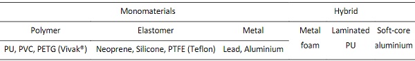
5.1. Monomaterial
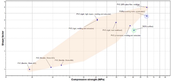
Polymers
Laminated glass interlayers are typically polymers (PVB, EVA, Ionomers). Therefore, they are commonly associated with shear loads, despite their satisfying levels of compressive strength. The viscoelastic nature of polymers allows the shape to adapt depending on the applied forces, which means that they are prone to creep under static load. Polymers can be shaped by injection molding and are commonly transparent or translucent.
The experiments of (Aurik,2017) and (Oikonomopoulou,2019b) tested PU and PVC in various thicknesses, under a static load of 480kN and 40kN respectively. While the PU70 and PU80 candidates were considered promising, their deformation did not stabilize during the experiments, which means failure due to creep could eventually still occur. However, it should be mentioned that the imposed static load translates to a nominal compressive stress of 11 MPa in the case of (Aurik, 2017) and 14.2 MPa for (Oikonomopoulou, 2019b), which is considerably higher than the anticipated permanent stresses occurring at a glass brick structure. (Akerboom,2016) chose a copolymer sheet, Vivak®, which is made from PETG (Polythylene terephithalate), the glycol-modified version of PET. As PETG is stiffer than PVC and PU, it is expected to have a better performance, however the results on its resistance to creep were inconclusive. Instead of PETG, PMMA is also a stiffer thermoplastic polymer, typically produced in sheets, with similar mechanical properties and shaping capabilities. Due to the many similarities among the two materials, only PETG will be considered for this study.
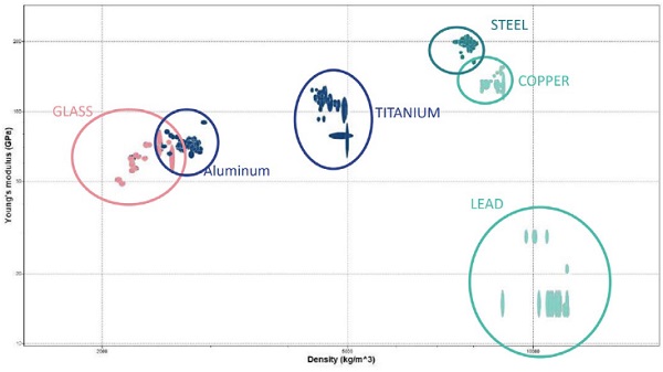
Fig. 5 presents the three material candidates together. While PVC presents a high range of strength and shape factor, depending on a varying shore hardness, PU and PETG appear to have more consistent properties.
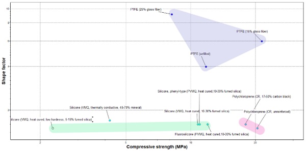
Elastomers
Elastomers, such as Neoprene, Silicone and PTFE (i.e. Teflon), are often placed in contact to glass in architectural applications, as window sealants, gaskets, washers and padding, often performing under long-term compression, which makes them promising candidates. In Fig. 6 it is evident that while all three materials have analogous compressive strength, PTFE presents the highest shape factor.
Neoprene is a Polychloroprene rubber that is flexible, resistant to tearing and produced in sheets of various thicknesses. As it requires minimum to no maintenance, neoprene is preferred in long-term constructions, often found in glass point fittings protecting glass panes from direct contact to the metalclamp (Patterson, 2011). Neoprene was also used as an intermediate between tested interlocking glass blocks and the steel machine (Oikonomopoulou, 2019b). The compressive strength of neoprene is expected to be satisfactory, and the flexibility of the material should allow it to adapt to the shape of the interlock, however, its creep behavior in the desired thickness and shape needs to beexperimentally verified. While for flat specimens a similar test might have already been realized, the interlocking geometry can potentially affect the material’s performance, as the load is not consistently perpendicular to the interlayer surface, thus requiring further investigation.
Silicone has a very similar consistency to glass (silicon dioxide), meaning when in contact with glass as it cures, a very strong bond can be formed. The removal of the silicone typically results in contamination of the glass surface, thus working against the initial goal of a demountable, recyclable interlocking system. Although a new promising silicone spacer product has been developed by Dow Silicones Belgium with the potential of easy removal, it has not yet been tested on non-flat surfaces(Hayez et al.,2019). Furthermore, silicones risks creeping under compression. To shape the silicone, casting the desired geometry or using silicone sheets products could be considered.
PTFE is often used as washers for different glass fixings (i.e. spider fixings, etc.). It is very durable, resistant to corrosion and non-stick. The glossy surface, reduced friction and risk of sliding, could be challenging in this application, as seen in the interlocking stalked column, and sanding might be required. Concerning shaping, a complex procedure such as compression molding the powder and sintering may be required for the geometry, since PTFE in its heated form is not very pliable. PTFE’s creep behavior also needs to be explored through testing, although it is more susceptible to tensile creep rather than compressive creep (DuPont, n.d.).
Metals
One of the main advantages of metals, is that in room temperatures they present virtually no creep. Nonetheless, placing glass in immediate contact to a metal can prove to be challenging. When glass is in direct contact to steel or titanium crack propagation often occurs. Indeed, typically between titanium inserts and glass elements a foil is placed to distribute the stresses. This has been experimentally confirmed also for cast glass assemblies by (Oikonomopoulou et al., 2015): compressive tests of individual glass blocks that were in direct contact with the steel surface of the testing machine, exhibited early failure at values between 20-30 MPa, whereas blocks that were tested with plywood as intermediary reached the load limit of the machine without failure, suggesting a compressive strength higher than 90 MPa.
Early failure due to peak stresses occurring between a thin copper interlayer and the glass brick surface was also observed at an experiment conducted by (Akerboom, 2016). But this condition is not true for all metals in contact with glass. In manycompressive glass experiments, which are performed by steel machines, an intermediate layer between the glass component and the machine is used to allow for even stress distribution; among the materials used are also thin metal sheets of lead and aluminium (Daryadel et al., 2016) (Sheikh et al., 2018), which have a Young’s Modulus similar or lower than glass.
The defining property of using these metals in direct contact to glass is their stiffness. As shown in Fig. 7 stainless steel is much stiffer than the other metals as well as glass, while lead and aluminium aremore ductile, which allow them to account for the micro-asperities of the glass surface while still withstanding the compressive load. Aluminum’s stiffness is more comparable to glass, while lead is more malleable and ductile. However, lead can be dangerous to humans as it is toxic, and its use is slowly being restricted. Moreover, lead has a considerably different thermal expansion coefficient compared to glass, which is discouraging as it can lead to considerable movements in the resulting construction. Regarding the shaping criterion, all metals can be cast in a mold or pressed, so no difficulties arise in that matter.
5.2. Hybrid
Hybrids are the combination of multiple materials, such as fiber reinforced polymers, sandwich structures, laminates, composites (Ashby et al., 2007), merged to obtain an optimized combination of the materials involved. One of the main disadvantages of advanced hybrid materials are the increased production costs and the added bonding among the multiple layers.
Metal foams
Metal foams are often used as panel interlayers, as they are lightweight and have an increased compressive strength. The properties of these materials concerning impact resistance (Liu et al., 2014), blast responses (Liu et al., 2012) and overall effectiveness (Torre, Kenny, 2000) are still under exploration. A foam geometry is too erratic to be in contact with a glass component, thus requiring smooth sheets on the outer faces to avoid friction with the glass surface. Furthermore, the shaping of a metallic foam to the required geometry is challenging. Most metal foam production methods result in the production of flat panels or symmetrical basic volumes (cubes, cylinders etc.). Methods making use of molds would be considered appropriate, such as metal powder slurries or investment casting, however it is still expected that the proposal could be too complex for fabrication.
Laminated PU
A main concern related to the elastomer and polymer candidates is their tendency to creep. In bridge bearings elastomeric pad bearings are commonly used, often laminated with metal plates in a sandwich form, and are subject to long-term compression. The metal plates reinforce the rubber layers, interfering with the extent to which it can creep, thus improving the overall stiffness of the bearing. The entire system is surrounded by a thin layer of rubber to protect the metal from corrosion (Lee, 1990).
Similarly, for the interlayer, a thin metal sheet could be sandwiched between two elastomer or polymer pieces, to create a hybrid reinforced interlayer. Such a process would significantly increase the manufacturing labor of the interlayer; the double amount of elastomer interlayers would have to be shaped, as well as the metal interlayers. Finally, the three items of each interlayer would have to be bonded to one unified object. The most common joining method for the two materials would be the application of an adhesive, as a mechanical bond would increase the complexity and labor.
Soft core aluminium
Implementing a softer core and harder outer layers, could be more effective than the opposite, as itcould improve the interlayers behavior on impact and vibrations. Such a material already exists in the market: Alucobond®. The material is a composite sandwich comprising of two sheets of aluminum over a polyethylene core (Kula, Ternaux, 2009). For the shaping, Alucobond® is produced in sheets, whichwould require bending post-production, or shaping the individual parts before bonding them.
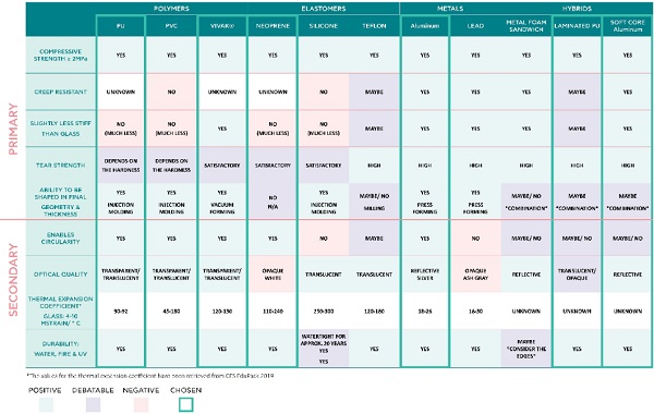
5.3. Overview & discussion
In Fig. 8 all of the discussed materials are presented, in a qualitative comparison of their performance according to the revised primary and secondary interlayer design criteria. From the discussed materials, the most promising candidates for dry-interlayers considered are; PU, PETG sheets (Vivak®), Neoprene Aluminium, Laminated PU and Soft-core Aluminium. The selected materials have distinct properties, which will eventually indicate which material family exhibits the most promising structuralperformance, for the interlocking glass assembly.
Due to the, comparatively, extended testing of polymers in similar applications already, the selection from this family will focus on examining a stiffer polymer, such as PETG, and on retesting PU in creep under the reviewed anticipated permanent compressive stresses. PU should be investigated both with and without a lamination (hybrid interlayer), to potentially demonstrate how effective lamination actually is.
From the Elastomer family, three materials were discussed: Neoprene, Silicone and PTFE. Concerning the primary criteria, neoprene’s rating is ambivalent. Α physical prototype is needed in order toconfirm if it can adapt to the required geometry, and compressive testing under static load is essential for investigating to what extent the materials creeps. Silicone, typically results in contamination of the glass surface, rendering it non-recyclable. Although there are potential products that could overcome this issue, as they are still under development the silicone interlayer candidate is discarded. PTFE would require extreme manipulating during manufacturing to achieve the desired geometry, which would be reflected on the overall cost. Furthermore, due to reduced friction, additional post processing for sanding might be needed to avoid the micro-rotations of the glass blocks.
For the Metals family, both aluminum and lead rate high on the primary criteria. Lead however, should be disqualified on account of its toxic properties and considerably higher thermal expansion coefficient. In addition, due to lead’s high density, the added load to the structure would burden the assembly for no reason. Aluminum is therefore the most promising candidate from this material family.
Finally, in case a monomaterial solution cannot meet the requirements of the structure, a hybrid proposal could be considered. The biggest disadvantage to using a hybrid interlayer, is the increased cost that will be needed for the processing of the material. Apart from the increased layers that need to be shaped, their joining is also of concern and needs to be further examined. The metal foam core sandwich requires additional treatment for the edges of the composite, otherwise water will pass through. Of the three, the bridge bearing prototype, has the highest risk of creeping, considering the extent to which the internal lamination will improve the overall interlayer creep performance is uncertain. The soft-core aluminum, though may appear to be the most promising, should be tested only if the monomaterial aluminum interlayer fails. Overall, the hybrid solution that will be chosen, will be considered after the indications of the monomaterial interlayers, as they are combinations of those.
In conclusion, to gain as much input possible from the experimental testing, materials from different families should ideally be tested under static load in flat and shaped specimens to assess their creep behavior. In Fig. 8 the materials chosen for investigation are highlighted: PU (with and without lamination), PETG (Vivak), Neoprene, Aluminium and Soft-core Aluminium.
5.4. Fabrication
The industrial fabrication process for forming each interlayer candidate in the desired size and shape is presented. In Table 5 the required information for the fabrication of all the interlayer candidates is collectively presented. The interlayer thicknesses vary greatly, from the thinnest 1mm aluminium to the thickest 5mm laminated. Neoprene requires the least processing, PETG is the only candidate that needs post-processing and the combined techniques required for the hybrid interlayers present the highest complexity. Specifically:
Table 5: Fabrication details of interlayer candidates
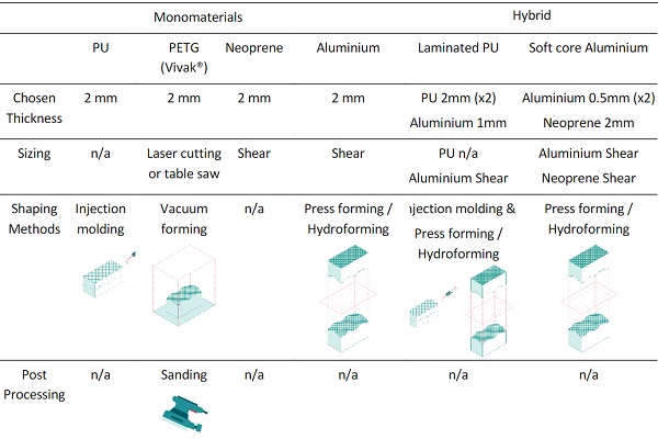
- PETG (Vivak®)
Although PETG is considered appropriate for laser cutting, saws and routers are more widely adopted for cutting the material. For shaping, Vivak® sheets offer superior thermoforming properties. The most extensively used processes are vacuum forming, free blown forming, and line bending, out of which vacuum forming is considering the most suitable method for the desired geometry. As the glossy PETG (Vivak®) surface, could risk increasing the contact imperfections through micro-rotations during assembly, the material should be sanded beforehand to increase the friction between the interlayer and glass blocks (Akerboom, 2016). The sheets could be sanded using wet sanding techniques. In previous studies, the chosen thickness was 2mm (Akerboom, 2016) (Barou, 2016), to allow for some potential creep without risking glass-to-glass contact.
- Neoprene
Neoprene is produced in sheets, which is typically industrially cut by die- or laser- cutting. After it is cut to the desired size, the flat specimens can be transferred on site and the material shall adapt to the shape merely through compression. Considering that thicker neoprene sheets tend to be stiffer,specimens thicker than 3mm are not considered appropriate alternatives, as they will fail to adapt well to the complex double-curved interlocking geometry and compromise the total stiffness of the assembly. Also, because the material is prone to creep, a thickness below 2mm is not advisable.
- Aluminium
To shape aluminum, various cold and hot forming methods exist (Zheng et al., 2018). Considering that dimensional accuracy is important, and the geometry is not too complex, cold forming is probably preferable. Sheet hydroforming could be an option, which results in fewer abrasions, better finishes, and requires only one mold piece. Otherwise, cold stamping could be used, which is faster in production, but requires both a male and female mold for the press. As there is no risk of creep, the thickness can be less than a neoprene or PETG interlayer, but not so too thin to account for the glass block microasperities, therefore a minimum of 2mm is proposed.
- Laminated PU
The shaping of this interlayer will be examined both with an adhesive and with a mechanical bond. Usually in such composites, an adhesive bond is preferred, to ensure a coherent performance throughout the entire surface. First the three layers would be separately shaped; aluminum as discussed above and PU through injection molding, as was done in previous experiments (Oikonomopoulou, 2019a). Then, to ensure a consistent adhesion, the shaped aluminum has to be properly prepared; degreasing the metal, abrasive grid blasting and applying the chemical primer are some main steps, as described by (Gallagher Corporation, 2017).
Using an adhesive though, means that the interlayer cannot be recycled, which is why, an alternative, reversible bond is also examined. If a flat specimen is produced and then pressed to the desired shape, the PU risks creeping in the process, resulting in an inconsistent thickness. Instead, the three layersmust be joined with the aluminum layer during or after the PU shaping. The PU could potentially be cast in a mold already containing a shaped, punctured aluminum layer, for the material to pour through the holes and enclose the aluminium, resulting in one unified object. If the aluminum is properly treated, then the PU will not stick to the aluminum, allowing for the layers to be separated and recycled. This process does not add significantly to the required labor, as no additional parts are needed, and a mold for casting the PU would be either way used.
Based on the results of (Aurik, 2017) and (Oikonomopoulou, 2019) 2mm thick PU layers are suggested, so that the added thickness of PU equals the best performing thickness. In between, a 1mm aluminum sheet can be placed, meaning the total thickness is 5mm.
- Soft core aluminium
A soft-core aluminum composite already exists in the market, under the name Alucobond®. The polymer panel and adhesive film are extruded in separate sheets, and slowly unraveled for the successful adhesive application. After the adhesive film is placed on the polymer, the layers are heated up and laminated with the aluminum. Such a process is tailored for the production of flat sheets, therefore, to achieve the desired geometry, press forming would be required.
If the interlayer were to be made reversible, a mechanical fastening would have to be implemented. The mechanism should be chosen so that the interlayer surface remains smooth, to avoid creating peak stresses at specific points and allow a full contact surface among the blocks and the interlayer. A connection imitating flush rivets or ring snaps could be adapted, where the rivets are placed and pressed before shaping, to overcome the risk of slanting. While this process would result in a recyclable interlayer, it requires the most intensive labor of the alternatives.
Concerning the interlayer’s thickness, the soft-core aluminium, would be considered if the single aluminum interlayer was too rigid. As a result, the added thickness of both aluminum sheets should be equal or less to the minimum thickness, meaning sheets of 0.5mm could be used. The soft core’s thickness should also be quite modest, as a larger thickness would increase the risk of creep. A 2mm thickness is proposed, bringing the total thickness to 3mm.
6. Assembly considerations & alternatives
To investigate the assembly considerations, a three-storey (9m) opening in an existing building is assumed, with a peripheral metal structure. The interlocking cast glass block assembly is to be used for the facade.
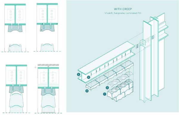
6.1. Detailing & Assembly Scenario 1: interlayers with creep risk
For the research, the starting point of the detailing is a metal frame structure, within which the glass blocks are placed, thus ensuring the assembly has a sufficient periphery constraint system. The assembly process and specific details are presented below for two different scenarios, based on the interlayer materials risk of creeping.
For the interlayers prone to creep, namely PETG (Vivak®), Neoprene and Laminated PU, an on-site pre-compression of the facade is required. This is done to bypass the settlement of the facade, that would inevitably occur gradually due to the interlayer material. Instead, pre-compressing the entire assembly on site, brings the interlayers to a phase of consistent structural performance and ensures a homogenous load transfer throughout the entire assembly¹. In any other case, due to the different dead load among the lower and upper rows, the thickness of the interlayer as well as the contact surface would exhibit great variations. The assembly and detailing for this scenario are presented below.
¹ Currently, there is only one realized dry-assembly glass-block structure (employing as well a steel-rod mesh) which demanded pre-compression, the Optical House in Japan. In this case a pre-cambered steel beam was used.
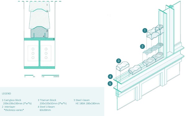
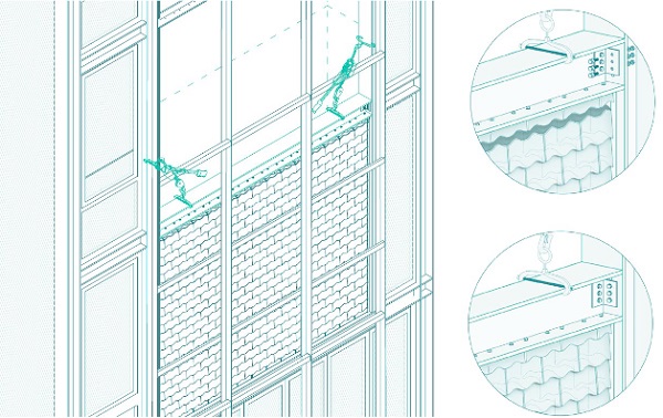
1. Main structural frame assembly: initially, the frame elements comprising the periphery system of the interlocking cast glass assembly are placed. To achieve the required pre-compression for the interlayers, the top beam is initially set in a higher position and will be later on lowered and secured.
2. Bottom detail assembly: the purpose of the bottom detail is to properly place and align the self-bearing assembly. A U-beam is to be fixed to the main structure, to act as rail for the bottom blocks to slide onto. To avoid casting additional glass blocks, solid metal blocks are shaped to have a flat bottom surface and an interlocking top face. Multiple blocks are preferred over having one continuous base element, as the fragmentation can help calibrate the individual units with higher precision. Once the solid metal blocks are all placed, interlayers are set upon them, before placing the glass blocks, as shown in Fig. 9. For this study, the material of the bottom blocks has been assumed to be titanium, due to its comparable thermal expansion coefficient (8.4-9.4*10-6/K) and high compressive strength (970MPa) (Granta Design Limited 2019), although depending on the visual intent other materials could also be considered.
3. Guides placement: the interlocking mechanism is not fully stable until its periphery system is properly constrained. In addition, although the interlocking mechanism does ensure self-aligning to a certain degree, it cannot entirely prevent eccentricity during construction, which is why an additional guide system is needed throughout construction, regardless the properties of the interlayer material.
4. Glass block placement: for the side assembly, another U-beam is proposed, within which the block will be enclosed. To protect the glass blocks, the U-beam will require a soft padding material on the inside (Fig. 10).
Ideally, the glass blocks should be laid from the edges moving inwards. If done otherwise, the last block to be placed will be edge blocks which need to be slid into the side U-beam, which increases complexity (Fig. 11). All rows apart from the last glass block row should be placed.
5. Top block placement: similarly to the bottom detail, to avoid casting additional glass geometries, for the top row titanium milled blocks are proposed, which are to be screwed from the top. The last row of glass blocks is not placed so that there is enough space to connect the titanium blocks to the top beam (Fig. 11). Furthermore, the height at which the beam shall be placed, depends on the amplitude of the interlocking mechanism. The beam must be placed as such that allows a person to place the last glass blocks from the side. Only then can the beam be lowered and secured to its final position. Any fabrication tolerances that occur can be accounted for by the repositioning of the beam.
6. Glass block placement: The last glass blocks can be placed.
7. On site compression: The top beam can be disassembled and lowered to its final position. To avoid the repeated need of a crane on site, throughout construction the beams are lowered with the use of come-alongs (Fig. 12). The new, lower position ensure the added compression needed to accommodate for the creep in the interlayers and stabilize the assembly.
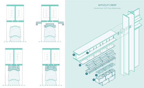
6.2. Detailing & Assembly Scenario 2: interlayers without creep risk
For interlayers that do not risk creeping, such as the aluminium and soft-core aluminium, as there is a reduced risk of buckling, taller assemblies can be targeted. A minor compression is still required on site, to stabilize the structure. However, as the compression is very little, the beams can be assembled in place, and the interlocking blocks will then fill the space in between. The assembly process is described step by step. When the process is identical to that of Scenario 1, only a brief title is provided.
- Main structural frame assembly
- Bottom detail assembly
- Guides placement
- Glass block placement
- Top block placement: due to the interlocking geometry, the last row of blocks cannot be simply pushed in. Instead, the top row of titanium interlocking blocks has to be modified. The block is divided in three pieces: a bottom piece, that accounts for the interlocking keys and has half the height of the total block and two pieces that can be placed from the sides. All three elements are screwed together from the top and are connected to the steel beam, as shown in Fig. 13. Concerning the assembly tolerances, a steel plate may be placed between the titanium blocks and the horizontal beam, whose thickness will be calculated based on the on-site size deviations. The required pre-compression is achieved through the tightening of the connection among the beams. Compared to the previous top detail, this scenario, is more suitable for restoration projects, where the boundary system cannot be altered, and the disassembly-maintenance process is easier.
- On site compression: unlike Scenario 1, when the interlayer does not risk creeping, a slight compression achieved by tightening the beam to column connection can suffice for stabilizing the interlocking assembly.
6.3. Overview
The two different assembly sequences, while very similar for the most part, have certain main differences, which derive from the interlayer material’s tendency to creep or not.
When the interlayer does not risk creeping, the assembly process is facilitated, because the top beam can be placed in its final position from the beginning, whereas, when there is a risk of creep, the beam needs to be placed at a higher position and then lowered to compress the assembly and interlayers on site. This process requires additional equipment (come-alongs) and labour. Furthermore, if aninterlayer does not creep, the interlocking assembly can expand to a larger envelope.
For the final evaluation of the facade system with different interlayer materials the following criteria were considered:
- Ease of assembly
This refers to the state in which the interlayer material arrives on site (flat or shaped), as well as the facade assembly process as described above (with and without the need for precompression).
- Ease of fabrication
Ease of fabrication concerns the fabrication, sizing, shaping and post-processing of the interlayer as well as how receptive to tolerances the interlayer is. For a more malleable interlayer, that can adjust and take tolerances, the production precision is not as critical as in a harder interlayer. In this category, Neoprene has a clear advantage, as it only requires cutting after its production. For Aluminum, the shaping will need to be very precise, to account for the stiffer nature of the material. PETG (Vivak®), might require post-processing (sanding), while the most complex fabrication, is required for the hybrid interlayers.
- Optical quality
A glass facade entails certain visual expectations, so the resulting appearance should not be overall disregarded. Depending on the interlayer materials discussed, the visual result can be: transparent, opaque and reflective. Out of the alternatives, the only candidate that can result in an entirely transparent assembly is PETG (Vivak®), with the view inside being almost completely unobstructed. The only opaque interlayer candidate is neoprene, in its white version, where the result is anticipated to be similar to the visual impression of existing adhesively bonded structures using a white adhesive, namely the Qwalala Structure (Paech, Goppert, 2018) and the Qaammat Pavilion (Oikonomopoulou et al., 2022). All interlayers featuring Aluminum, would have a more dominant visual presence.
- Cost
This is dependent on many factors; the materials themselves, the required shaping processes, the assembly process, as well as fluctuations of market demand. A detailed cost analysis of the chosen interlayer materials is beyond the scope of this work. However, a general ranking based on the comparative cost of the material, their fabrication processes and the assembly challenges is presented, acknowledging that it could vary depending on the market at the point of construction. Due to the increased labor and materials required for the hybrid interlayers, they are expected to be the most expensive alternatives. Neoprene which required no further processing after being produced should be the least expensive.
From the different interlayer candidates, the PETG (Vivak®) and Aluminum alternatives appear to be the most promising. The hybrid interlayers, as mentioned previously, significantly increase the fabrication difficulty and cost of the assembly, while the Neoprene interlayer, negatively affects the assembly process. The comparison in Fig. 14 also includes conventional hollow glass block assemblies as a reference, despite their not having a structural role. While the table offers a solid indication of the strengths and weaknesses each assembly entails, a structural validation of the dry interlayer materials for interlocking geometries is required for the assessment to be complete, as described in the following section.
7. Conclusions and recommendations
The aim of this research is to discover the effect of different interlayer materials on the performance and construction potential of a dry assembly, interlocking cast glass block assembly. This interlayer ensures an even load distribution among the glass components and accounts for the surface micro-asperities, preventing early failure. Prior to this research, limited exploration concerning the interlayer materiality had been made, as the interlocking cast glass block assembly is in itself a novel structure.
Through the re-definition of the performance criteria, an extended examination of various materials used with glass or as interlayers, limited the candidates to: PETG (Vivak®), Neoprene, and Aluminum, from the monomaterial families, and Laminated PU and Soft-core Aluminum as hybrid material choices. The extent to which the unique properties of all materials affect the fabrication, detailing and assembly of the interlocking structure were examined.
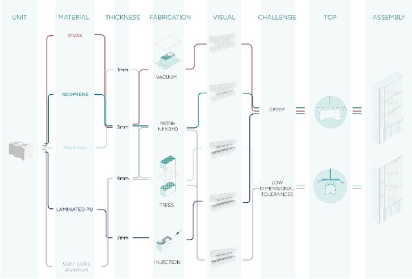
The present research intentionally does not conclude in a single suitable interlayer material. Instead, the exploration among different material families, results in a general guide of affected parameters during fabrication and construction of the interlocking cast glass assembly. The cause and effect starting from the choice of an interlayer material to the final assembly is illustrated in Fig. 15. Depending on the intent and priority of a project, the most suitable route can be followed. For example, if a high-level transparency is required, then PETG (Vivak®) is most likely to serve the intent. If, however one would intend on having the interlocking assembly on an extended facade, then interlayers that do not risk creeping would be encouraged, such as Aluminium.
Thus, Fig. 15 serves a selection roadmap that can guide the engineers and architects on the most suitable material based on the prioritized criteria of the respective case-study.
Concerning the interlayer fabrication, each material dictates which shaping method is best to achieve the desired geometry and what thickness should be preferred. In the case of monomaterial interlayers, the production procedures are quite common, while the selection of a hybrid interlayer would result in increased complexity.
The detailing and assembly of the interlocking structure are mostly affected, when considering the different interlayer materials. The most definitive property of the interlayer candidates for this phase, is their tendency or not to creep, which in turn defines the entire assembly’s requirements. Based on the material properties, two distinct cases are analyzed.
When the risk of creep is evident (PETG (Vivak®), Neoprene, Laminated PU), the entire assembly requires an additional on-site compression, to evade the settlement of the facade, that would inevitably occur due to the interlayer material. Compressing the glass block wall on site, ensures a consistent structural performance of the interlayers and a homogenous load transfer throughout the entire assembly. To do so, the top beam needs to change position during construction, requiring some additional equipment. Furthermore, as these interlayers are more vulnerable to buckling, the maximum allowable height of the assembly is limited. Without the fear of creep (Aluminum, Soft core Aluminum), the assembly can expand, resulting in a larger load-bearing structure.
Finally, the most obvious result of changing the interlayer material, is the appearance of the assembly. Selecting among transparent, opaque or reflective interlayers, has an immediate effect on the way the assembly reacts with light, the degree to which the interlocking geometry is accented and the overall feeling of the facade.
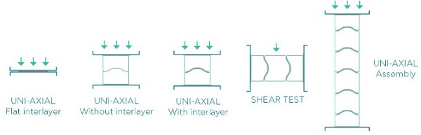
Due to restrictions related to the Covid-19 pandemic, it was not possible to perform any structural tests within the duration of the presented research. Thus, the main recommendation following this research would be to perform relevant experimental tests, which will offer an indication of which material family is better suited for the particular assembly, as each material family is represented in the proposed alternatives. The expected tests would include testing flat and shaped interlayers of the desired final thickness under static load for creep, out of plane shear tests for lateral loads and uniaxial tests of taller assemblies for bending. While creep was considered a defining material property for this research, the structural validation of the proposed interlayers may reveal additional properties that affect the assembly. Considering that the interlocking assembly is a novel system, there are still many aspects that can be further explored. The recommended validation tests are shown in Fig.16.
Regarding the assembly, the key points and principles critical in such a structure have been highlighted. Apart from self-supporting envelopes, the interlocking assembly has the potential to be applied to other compressive members as well, such as columns or arches. The reversibility of the system makes such an assembly a promising proposal for restoration projects as well (Barou, 2016).
Finally, additional investigation of the thermal performance should be carried out and set as supplementary design parameters. The monolithic nature of the cast glass blocks results in relatively poor insulation properties and a presents high risk of surface condensation.
References
Akerboom, R.: Glass Columns, exploring the potential of free-standing glass columns assembled from stacked cast elements. Delft University of Technology, Delft (2016)
Ashby, M. F., Shercliff, H., Cebon, D.: Materials: Engineering, Science, Processing and Design Butterworth-Heinemann, Oxford (2007)
Aurik, M., Snijder, A., Noteboom, C., Nijsse, R., Louter, C.: Experimental analysis on the glass interlayer system in glass masonry arches. Glass Structures & Engineering 3(2), pp. 335-353 (2018) doi:10.1007/ s40940-018-0068-7
Aurik, M.: Structural Aspects of an Arched Glass Masonry Bridge. Delft University of Technology, Delft (2017)
Barou, L: Transparent restoration, Delft University of Technology, Delft (2016)
Daryadel, S. S., Mantena, P. R., Kim, K., Stoddard, D., & Rajendran, A. M.: Dynamic response of glass under low-velocity impact and high strain-rate SHPB compression loading. Journal of Non-Crystalline Solids, Elsevier, 432, pp. 432–439 (2016) https://doi.org/10.1016/j. jnoncrysol.2015.10.043
DuPont. (n.d.). Teflon PTFE: fluoropolymer resin. Retrieved January 6, 2020, from http://www.rjchase. com/ptfe_handbook.pdf
Gallagher Corporation: Principles of Bonding Cast Polyurethane to Metals, Gallagher Corporation [Video file]. (2017) Retrieved from https://www.youtube.com/watch?v=lxQYfjoZr_w
Granta Design Limited: CES EduPack (2019)
Hannah, B.H.: Jaume Plensa: Crown Fountain as Carnivalesque. Umi Dissertation Publishing, USA (2009)
Hayez, V., Gubbels, F., Chambard, G.: Maximizing façade transparency with crystal clear silicone spacers. Glass performance days (2019)
Jacobs, E.A.M.: Structural consolidation of historic monuments by interlocking cast glass components. Delft University of Technology, Delft (2017)
Kula, D. K., & Ternaux, E. T.: Materiology: The Creative’s Guide to Materials and Technologies (Rev. ed.). Frame Publishers, Amsterdam (2009)
Liu, C., Zhang, Y. X., & Heslehurst, R.: Impact resistance and bonding capability of sandwich panels with fibre–metal laminate skins and aluminum foam core. Journal of Adhesion Science and Technology, 28(24), pp. 2378–2392. (2014) https://doi.org/10.1080/016942 43.2014.967744
Liu, X., Tian, X., Lu, T. J., Zhou, D., & Liang, B.: Blast resistance of sandwich-walled hollow cylinders with graded metallic foam cores. Composite Structures, 94(8), pp. 2485–2493. (2012) https://doi. org/10.1016/j.compstruct.2012.02.029
McKeen, L. W.: Introduction to Creep, Polymers, Plastics and Elastomers. The Effect of Creep and Other Time Related Factors on Plastics and Elastomers, pp. 1–41 (2015) https://doi.org/10.1016/b978- 0- 323-35313-7.00001-8
Oikonomopoulou F., Bristogianni T., van der Velden M., Ikonomidis K.: The adhesively-bonded glass brick system of the Qaammat Pavilion in Greenland: From research to realization. Journal of Architecture, Structures and Construction, Springer, Heidelberg (2022) https://doi.org/10.1007/s44150-022-00031-2
Oikonomopoulou, F., Bristogianni, T., Barou, L., Veer, F.A.: Dry interlayers out of cast polyurethane rubber for interlockingcast glass structures: experimental exploration and validation. In: Proceedings of the Seventh International Conference On Structural Engineering, Mechanics And Computation (SEMC). Cape Town (2019a)
Oikonomopoulou, F.: Unveiling the third dimension of glass, A+BE, Rotterdam (2019b)
Oikonomopoulou, F., Bristogianni, T., Barou, L., Jacobs, E., Frigo, G., Veer, F., & Nijsse, R.: Interlocking cast glass components, Exploring a demountable dry-assembly structural glass system. Heron, 63(1/2), 103-138, (2018)
Oikonomopoulou, F., Bristogianni, T., Veer, F.A., Nijsse, R.: The construction of the Crystal Houses façade: challenges and innovations. Glass Structures & Engineering, pp. 1-22 (2017). https://doi.org/10.1007/s40940-017-0039-4
Oikonomopoulou, F., Veer, F.A., Nijsse, R., Baardolf, K.: A completely transparent, adhesively bonded sodalime glass block masonry system. Journal of Facade Design and Engineering 2(3-4), 201-222 (2015). https://doi.org/10.3233/FDE-150021
Oikonomopoulou, F., Veer, F., Nijsse, R. and Baardolf, K.: A completely transparent, adhesively bonded soda-lime glass block masonry system, In U. Knaack and T. Klein, Journal of facade design and engineering Vol. 2, No.3-4, IOS Press, Delft (2014)
Oshima, K.T.: The Architectural Review, Optical Glass House, Hiroshima, Japan. 〈https://www.architectural-review.com/today/optical-glass-house-hiroshima-japan/8638709.article〉. (2012)
Paech, C., Göppert, K.: Innovative Glass Joints - The 11 March Memorial in Madrid. In: Louter, C., Bos, F., Veer, F. (eds.) Challenging Glass: Conference on Architectural and Structural Applications of Glass, pp. 111-118. IOS Press, Delft, (2008)
Paech, C., Göppert, K.: Qwalala – Monumentale Skulptur aus verklebten Glasblöcken. ce/papers 2(1), 1-12 (2018)
Parascho, S., Han, I.X., Walker, S., Beghini, A., Bruun, E.P.G. and Adriaenssens, S.: 'Robotic vault: a cooperative robotic assembly method for brick vault construction', Construction Robotics, 4 pp.117-26.(2020)https://doi.org/10.1007/s41693-020-00041-w
Patterson, M.: Structural Glass Facades and Enclosures (1st ed.). Wiley, Hoboken (2011)
Sheikh, M. Z., Wang, Z., Suo, T., Li, Y., Zhou, F., Ahmed, S., ... Wang, Y.: Dynamic failure of annealed and chemically strengthened glass under compression loading. Journal of Non-Crystalline Solids, 499, pp. 189–200. (2018) https://doi.org/10.1016/j. jnoncrysol.2018.07.043
Torre, L., & Kenny, J. M.: Impact testing and simulation of composite sandwich structures for civil transportation. Composite Structures, 50(3), pp. 257–267. (2000) https://doi.org/10.1016/s0263- 8223(00)00101-x
Wurm, J., & Peat, R.: Glass Structures: Design and Construction of Self-supporting Skins. Birkhauser, Boston (2007)
Yang, H.: Facade design with interlocking cast glass system. Based on structural behavior investigation., Delft University of Technology, Delft (2019)
Zheng, K., Politis, D. J., Wang, L., & Lin, J.: A review on forming techniques for manufacturing lightweight complex—shaped aluminum panel components. International Journal of Lightweight Materials and Manufacture, 1(2), pp. 55–80. (2018) https://doi. org/10.1016/j.ijlmm.2018.03.006