First presented at GPD 2017
A 35’ tall all-glass storefront designed and constructed in a market that had no prior experience with glass of that scale, and almost three feet of vertical movement between the glass storefront and the tower above. The design and execution of a structural glass façade required input and expertise from a wide range of professionals, including the Architect, Engineer, Specialty Glass Engineer and Builder. By assembling the core team of specialists, the Owner achieved their goal of developing an exceptional and iconic building in the heart of Salt Lake City, Utah.
Project Overview
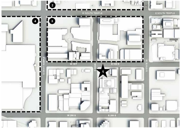
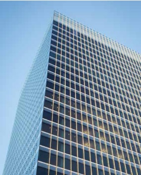
111 Main is a 24-story speculative office tower located at the corner of South Main and E 100 South Street in the heart of downtown Salt Lake City, Utah, and only blocks away from Temple Square, the historic headquarters of the Church of Jesus Christ of Latter-day Saints. The building is connected on the ground floor to the Eccles Theatre, a new 2,500 seat performing arts center built concurrently to the 111 Main tower, and is directly across the street from City Creek Center, a 20-acre mixed use development with retail, commercial and residential program completed in 2012. (Refer to Figure 1.)
Design of 111 Main was nearly complete when the project was acquired by City Creek Reserve, Inc. (CCRI). CCRI is the real estate investment portfolio of the Church of Jesus Christ of Latter-day Saints and a major developer of commercial real estate in Salt Lake City, Utah. CCRI’s recent developments include the City Creek Center.
In the years leading up to their acquisition of the project, CCRI had made significant investments in the revitalization of downtown Salt Lake City. CCRI viewed the 111 Main project as an opportunity to create a landmark building within this newly re-energized downtown corridor.
Site Complexities
The 111 Main tower is the cornerstone of a city block identified by the Salt Lake City Redevelopment Agency (RDA) as the ideal location for a new performing arts center. Contained within this city block was a 90,000 square-foot (8,360 square-meter) L-shaped property owned by the RDA. The majority of this property was intended for use by the new performing arts center. A portion of the property was to be sold to the 111 Main development team for construction of a new office tower.
Economic feasibility of the office tower required a 21,000 square-foot (1,950 square-meter) footprint. However, to accommodate essential program elements, the new performing arts center required a footprint of nearly 75,000 square-feet (6,970 square-meter). For the tower project to move forward, a 21,000 square-foot (1,950 square-meter) tower floorplate would need to be constructed on a 15,000 square-foot (1,390 square-meter) site.
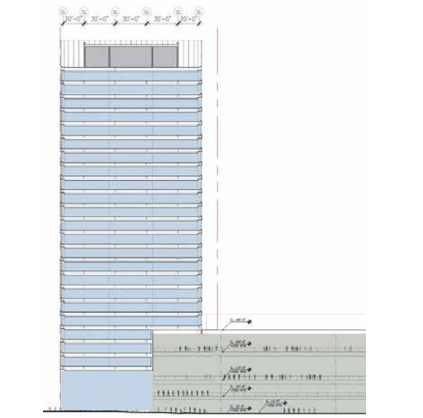
The northern edge of the building is aligned with the property line along 100 South Street. Above Level 5, the southern edge of the building is suspended approximately 47.5 feet (14.48 meters) over the southern property line. The performing arts center encroaches 45 feet (13.72 meters) into the tower footprint between the ground floor and Level 5. CCRI acquired air rights from the RDA, and SOM Architects and Structural Engineers conceived a building with rooftop trusses to suspend the southern lease span of the tower over the new five-story performing arts center. (Refer to Figure 2.)
Building Form
The tower has a rectangular form beginning at Level 5 and continuing up the full height of the building. The tower footprint is a 155 foot (47.24 meter) by 135 foot (41.15 meter), 21,000 square-foot (1,950 square-meter) rectangle. Levels 3 and 4 create a 155 foot (47.24 meter) by 87.5 foot (26.67 meter) rectangle, justified to the northern edge of the tower above. Level 2 is a mechanical level enclosed by intake and exhaust louvers, and setback 2.5 feet (0.76 meters) from the property lines along the west and north. The ground floor is 37 feet (11.28 meters) tall and has a footprint of 14,000 square-feet (1,300 square-meters).
Structural Performance
Salt Lake City is located in Seismic Design Category D, near the active Salt Lake Segment of the Wasatch Fault Zone. As a result, the building is designed to accommodate severe seismic activity. With an above grade building height of 387 feet (118 meters) the building structure was designed using a performance-based seismic design procedures, which required additional independent peer reviews.
The building foundation is driven steel HPpiles, reaching depths over 100 feet (30.48 meters) below grade, supporting a central reinforced concrete core. The reinforced concrete core extends from 18 feet (5.5 meters) below grade up to the mechanical penthouse level (Level 25) at 351 feet (107 meters) above grade. The mechanical penthouse level consists of a two-way steel truss system suspending 18 perimeter columns.
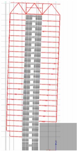
The perimeter columns along the south reach down to Level 5. In order to create a balanced system, on the west, north and east the perimeter columns reach down to Level 2. All floors of the tower are supported from the suspended perimeter columns, which are supported by two-way steel truss system at the roof. Gravity loads are transferred from the hat trusses to the top of the reinforced concrete core walls using six steel spherical structural bearings.
The two-way steel truss system at the roof supports 23 suspended levels on the west, north and east, and 20 suspended levels on the south. The reinforced concrete core walls are the only connection between the tower and the foundation, and account for the transfer of all gravity, wind, and seismic loads.
The building’s unique structural design combined with the anticipation of severe seismic activity result in significant differential movements, mostly between Level 1 and Level 2. At this location design of the exterior enclosure and building systems were required to accommodate significant movement: vertical movement up to 32 inches (81.3 centimeters), parallel movement up to 3.3 inches (8.4 centimeters), and perpendicular movement up to 3.3 inches (8.4 centimeters). (Refer to Figure 3.)
Building Design: General
There were three fundamental principles that served to guide the design of the 111 Main tower: transparency, visual depth and performance.
Transparency was engaged as the primary means of connecting the building and its occupants to the site, at the human scale in response to the dense urban setting, and at the environmental scale in response to its geographic location in a valley bordered by the Wasatch and Oquirrh mountain ranges.
Visual depth is used in the massing and the design and detailing of exterior enclosure as a juxtaposition to the transparency. The visual depth of the exterior enclosure creates a presence in the skyline and on the street that is constantly changing and invites people closer to explore the building. Performance requirements included accommodation of challenging movements from the building structure, an emphasis on human health and comfort, and an understanding of the regional market and tenant demands. At each step in the design process these principles were rigorously considered and articulated in the resolution of building systems and exterior enclosures.
Exterior Enclosure Design: Tower Enclosure
The primary building exterior enclosure is comprised of a unitized curtain wall. Typical units are 5 feet (1.5 meters) wide by 13.75 feet (4.19 meters) tall, corner units are 7.5 feet (2.3 meters) wide by 13.5 feet (4.1 meters) tall, and the floor to ceiling vision glazing is 9.42 feet (2.87 meter) tall. At Level 24 the typical units are 5 feet (1.5 meters) wide by 15.75 feet (4.8 meters) tall, the corner units are 7.5 feet (2.3 meters) wide by 15.75 feet (4.8 meters) tall, and the floor to ceiling vision glazing is 12.75 feet (3.9 meters) tall. The wide corner units combined with floor to ceiling vision glazing serve to maximize transparency, especially at the corners, offering occupants breathtaking and unobstructed views of the surrounding valley and mountain ranges.
A shadow box at the spandrel features a series of horizontal aluminum extrusions painted to accentuate the shadows they create. At each of the vertical mullions there are 10-inch deep (25.4 centimeter) glass fins with a custom frit pattern. The horizontal lines and the depth of the shadow box combined with the vertical lines and the depth of the glass fins are used to create visual depth in the façade. (Refer to Figure 4.)
Located in a dry and arid climate at an elevation of approximately 4,250 feet (1,295 meters) above sea level, the building systems and exterior enclosures are required to accommodate significant temperature swings (basis of design was an outside cooling condition of 97.4°F (36.3°C) and an outside heating condition of 9.3°F (-12.6°C)) to maintain an indoor space temperature of 72°F (22.2°C).
42,935 square-feet (3,990 square-meters) of the exterior enclosure faces due south, 39,815 square-feet (3,700 squaremeters) faces east and west, and 47,200 square-feet (4,385 square-meters) faces due north. With an average of 70% window to wall ratio, it was important to minimize solar heat gain. A gray tinted 0.375 inch (9.52 millimeter) float glass on the outer lite of the insulated glazing unit was installed with a Low-E coating on the #2 surface.
For occupant comfort, glass deflection was limited to a maximum of 1 inch (25.4 millimeters) at the center of the vision area. Because wind loads in some areas were in excess of 65 miles per hour (105 kilometers per hour) the insulated glazing unit was comprised of a 0.375 inch (9.525 millimeter) outer lite, 0.5 inch (12.7 millimeter) air space, and a 0.375 inch (9.525 millimeter) outer lite.
The anticipated seismic drift between any two of the typical floor slabs of the tower, spaced at 13.75 foot (4.2 meter) apart, is 3.3 inches (83.8 millimeters). Seismic drift is accommodated in the unitized curtain wall through a combination of sliding and tilting of the units.
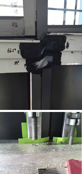
Further complicating the design of the unitized curtain wall, the construction schedule required that installation of the unitized curtain wall begin well before the building loads were transferred from temporary shoring to the rooftop trusses. This required an unusually large amount of adjustment to be designed into unit to unit joinery at the curtain wall anchors. (Refer to Figures 5A and 5B.)
Building Design: Ground Floor Lobby
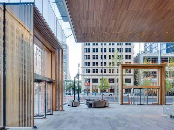
It was important to CCRI that the L-shaped lobby at the base of the 111 Main tower be a public, open and active space. The design of the ground floor lobby was conceived of as a living room for the city, a large space that functions at a human scale by offering a place to gather, lounge and repose.
Along the southern edge of the lobby there is a large 29.5 foot (9 meter) wide by 32.5 foot (9.9 meter) tall interior glass storefront, the bottom 10.5 feet (3.2 meters) of which slides open providing a direct connection between the tower lobby and the great hall of the adjacent performing arts center.
At the opposite end of the L- shaped lobby is a cafe, also open to the tower lobby. The connections to the performing arts center and the café – in combination with a 40 foot (12.2 meter) long water feature, a 36 foot (11 meter) by 19.5 foot (5.94 meter) tall media wall art installation, and a collection of couches, tables and chairs – serve to inspire public curiosity and engagement within the space, and encourage free-flow through the lobby.
Exterior Enclosure Design: Lobby Enclosure
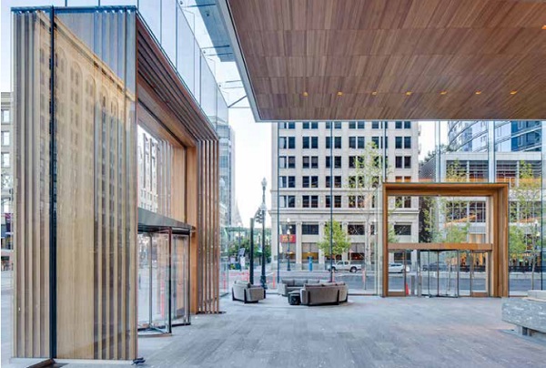
To promote the lobby’s connection to its urban context and inspire public use, the lobby exterior enclosure along public ways on the north and west was designed to be a transparent all-glass façade. Except at the entries, the storefront is constructed of only one material – laminated ultra-clear glass. Using this single material and a generous 10 foot (3 meter) by 35 foot (10.7 meter) module the number of material intersections is minimized and each detail is carefully crafted to support the principles of transparency and visual depth. (Refer to Figure 6.)
Because the building structure is suspended from the roof, the 37 foot (11.28 meter) tall ground floor is column-free. The all-glass lobby exterior enclosure is gravity supported at grade resulting in extreme differential movement between the enclosure and the tower above. The all-glass exterior enclosure is required to accommodate +14 inches (35.6 centimeters) and -18 inches (45.7 centimeters) of vertical movement between the base of the suspended tower and the ground, and 3.3 inches (8.4 centimeters) each of parallel and perpendicular movement. Focused on the principles of transparency and visual depth, cumbersome and opaque expansion joints were replaced with a system design able to accommodate these movements.
The primary elements of the all-glass lobby exterior enclosure are described below, and are as follows:
1. Typical plan detail
2. Corner plan detail
3. Pivot section detail
4. Corner section detail at skylight
5. Lobby enclosure return
6. Lobby entrance portals
1. TYPICAL PLAN DETAIL: Spaced at 10 feet (3 meters) on center, each of the laminated glass stabilization fins consists of four 0.5 inch (12 millimeter) sheets of ultra-clear low iron glass. The laminated glass stabilization fins are set behind the laminated glass face panels to provide a continuous line of resistance to positive and negative wind loads and eliminate the need for visible metal fittings. The laminated glass face panels are 10 feet (3 meters) wide by 35 feet (10.7 meters) tall. Each laminated glass face panel consists of two 0.5 inch (12 millimeter) sheets of ultraclear low iron glass. Glass manifestation is provided in the form of a horizontal line of small white rectangles that are screen printed onto the #2 surface of each laminated glass face panel. The laminated glass face panels and the laminated glass stabilization fins are cantilevered from the ground in an 8 inch (20.32 centimeter) deep steel channel.
A continuous vertical line of black structural silicone adheres the laminated glass face panels to the laminated glass stabilization fins. The use of black silicone is visually recessive in elevation, and the use of large glass panels with a minimal number of materials at the intersecting joinery reinforces the principle of transparency.
At the base of the all-glass lobby exterior enclosure, nestled between each of the laminated glass stabilization fins, is a series of linear trench heaters. The trench heaters force warm air up the interior side of the all-glass exterior enclosure reducing condensation.
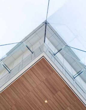
2. CORNER PLAN DETAIL: The lobby exterior enclosure has three glass corners, one at the main building corner, and two where the enclosure returns to meet the building. Because the laminated glass corner panels at the corner act to support one another, there are no laminated glass stabilization fins at the corners of the all-glass lobby enclosure. The converging 10 foot (3 meter) by 35 foot (10.7 meter) laminated glass face panels are mitered and joined with a 0.75 inch (19 millimeter) black silicone joint. This joint configuration allows the laminated glass corner panels to support each other in shear, deform in a seismic event, and provides ultimate transparency.
3. PIVOT SECTION DETAIL: While the all-glass lobby exterior enclosure is laterally supported by a laminated glass purlin joined to the tower, the vertical movements anticipated between the all-glass lobby exterior enclosure and the tower suspended above required that the enclosure be isolated from the tower. In order to satisfy these opposing criteria the glass roof of the all-glass lobby exterior enclosure was designed to act as a movement joint.
The 6 foot (1.8 meter) wide laminated glass skylight panels consists of two 0.5 inch (12 millimeter) sheets of ultra-clear low iron glass. The laminated glass skylight panels are supported every 10 feet (3 meters) by a laminated glass purlin. The laminated glass purlin consists of four 0.5 inch (12 millimeter) sheets of ultra-clear low iron glass. Designed around a mortise and tenon joint, on one end of the laminated glass purlin the outer two layers of laminate are held back, and at the top of the laminated glass stabilization fins the inner two layers of the laminate are cut short.
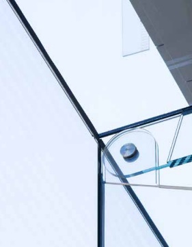
The laminated glass purlin is spliced into the laminated glass stabilization fin and joined with a stainless steel pin. The other end of the laminated glass purlin is pinned to a concealed linear guide rail. The guide rail is mounted to the base of the tower, allowing for free movement between the all-glass lobby exterior enclosure and the tower above. The laminated glass skylight panel is joined to the laminated glass face panel with a 1.63 inch (41.4 millimeter) black silicone joint, and to the laminated glass purlin with a 0.75 inch (19.05 millimeter) black silicone joint. (Refer to Figure 7.)
Similar to the typical plan details, the relatively thin and singular black silicone joints recede in elevation. The stainless steel pin, the laminated glass stabilization fin and laminated glass purlin are shaped to express the rotational movements they have been designed to accommodate.
4. CORNER SECTION DETAIL AT SKYLIGHT: The moment where a number of complex movements converge, the all-glass skylight corner was designed to encourage the laminated glass skylight corner panels to shift above or below one another in a seismic event. The laminated glass skylight corner panels are trapezoidal in shape. The panel is orthogonal and parallel to the building at the front and back edges, and at the laminated glass stabilization fin located 10 feet (3 meters) away from the corner.
On the corner edge, the laminated glass skylight corner panels are cut at an angle to meet the building above. To encourage one laminated glass skylight corner panel to slide up and over the adjacent laminated glass skylight corner panel, the joint between the two laminated glass skylight corner panels was required to be cut at a 30 degree angle. Because a 30 degree angle exceeds glass fabrication standards, the edge of each of the laminated glass skylight corner panels was cut at a 45 degree angle.
The mitered edge was finished to receive a custom stainless steel shape designed to transition the 45 degree angle of the laminated glass skylight corner panel to the 30 degree angle required to encourage one laminated glass skylight corner panel to slide up and over the adjacent panel.
The custom stainless steel shape was shop applied to the mitered edge of each of the laminated glass skylight corner panels. The exposed portion of the cast stainless steel shape is approximately 0.75 inch (1.9 millimeter) wide, and is aligned with the vertical 0.75 inch (1.9 millimeter) silicone joint at the vertical corner panels. There are thin black silicone lines on either side of the exposed portion of the cast stainless steel shape. (Refer to Figure 8.)
A 0.375 inch (9.5 millimeter) wide silicone joint separates the two laminated glass skylight corner panels. The primary water line is a silicone sheet bridging over the top of the two laminated glass skylight corner panels, adhered with a silicone sealant at the edge of each of the laminated glass skylight corner panels.
5. LOBBY ENCLOSURE RETURN: The east and south property lines are shared lot lines. The ground floor exterior enclosure along these shared lot lines consists of reinforced concrete, CMU block, and steel framed walls, all clad with aluminum panel or cement plaster and cantilevered from the ground.
At both the northeast and the southwest corners of the building the all-glass lobby exterior enclosure returns to meet an aluminum clad wall assembly. Because the adjacent wall assemblies are isolated from the base of the suspended tower using conventional seismic joints, it was necessary also to isolate the all-glass lobby exterior enclosure from these adjacent wall assemblies.
On the southwest corner the 35 foot (10.7 meter) tall laminated glass return panel is terminated behind an aluminum clad wall at a 12 inch (30.48 centimeter) wide by 2 inch (5.08 centimeter) deep vertical steel tube cantilevered from the ground and connected to the base of the tower with a concealed linear guide rail. The laminated glass return panel is captured in a continuous built-up steel channel mounted on the vertical steel tube, and running the full height of the laminated glass return panel.
The vertical steel tube is isolated from the adjacent aluminum-clad wall assembly by 4 inches (10.16 centimeters) in all directions to accommodate the anticipated differential movement between these two assemblies. Vertical aluminum panel clad hinged seismic joints are provided on both the interior and exterior sides of the laminated glass return panel, and a 18 inch (45.72 centimeter) tall slot is provided above the laminated glass return panel and built-up steel channel to accommodate vertical movement.
The laminated glass skylight panel is held back from the face of wall by approximately 1 inch (2.5 centimeters). An angled horizontal joint in the aluminum panel tracks the line of the laminated glass skylight panel, and a silicone sheet is adhered to the edge of the laminated glass skylight panel on one end, and to the waterproofing membrane behind the aluminum clad panels on the other.
The laminated glass return panel on the northeast corner is resolved in much the same way as the laminated glass return panel on the southwest, except that the laminated glass return panel on the northeast corner is only 20 feet (6.1 meters) tall and is set on top of a 10 foot (3 meter) tall steel framed entry portal.
The execution of an all-glass expression of the lobby exterior enclosure returns was essential to the resolution of both aesthetic and performance considerations. The all-glass expression of the southwest and northeast corners created an additional dimension – the all-glass lobby exterior enclosure was given a cubic form further articulating its transparency. By terminating the all-glass lobby exterior enclosure into an adjacent wall assembly parallel to the laminated glass face panels, visual depth was achieved and used to emphasize the transparency of the allglass lobby exterior enclosure. Additionally, by implementing details similar to those already used at the all-glass lobby exterior enclosure main building corner and lateral supports, the number of unique details was minimized and the need for additional and complex movement joints was eliminated.
6. LOBBY ENTRANCE PORTALS: The two public lobby entrance portals, one on 100 South Street and one on Main Street, are constructed of glass, steel and wood. Two modules wide, a structural steel frame was designed to support two of the lobby exterior enclosure laminated glass face panels and the three laminated glass stabilization fins supporting them.
On the exterior side of the steel frame, two 2.5 foot (0.76 meter) deep by 20 foot (6.1 meter) tall laminated glass side panels support a 2.5 foot (0.76 meter) deep by 20 foot (6.1 meter) wide laminated glass lintel. On the interior side of the steel frame, two 5 foot (1.52 meter) deep by 20 foot (6.1 meter) tall laminated glass side panels support a 5 foot (1.52 meter) deep by 20 foot (6.1 meter) wide laminated glass lintel.
The four laminated glass side panels consist of three 0.5 inch (12 millimeter) sheets of ultra-clear low iron glass. The two laminated glass lintel panels consist of three 0.5 inch (12 millimeter) sheets of ultra-clear low iron glass and one 0.3 inch (8 millimeter) sheet of ultra-clear low iron glass. The steel frame, laminated glass side panels and laminated glass lintel panels serve to define the 20 foot (6.1 meter) wide by 20 foot (6.1 meter) tall by 7.5 foot (2.29 meter) deep lobby entrance portal.
Transparency at the lobby entrance portal is achieved by using solid materials judiciously, and by engaging the laminated glass panels to support solid materials when possible. Given the transparent nature of the all-glass lobby exterior enclosure, bringing prominence to the building entrance portals within in the urban context was a key criteria for the design of the enclosure. It was the introduction of wood, a quarter sliced California Eucalyptus, which served to set the entrance portals apart from the adjacent all-glass lobby exterior enclosure and to add an inviting warmth to the façade.
Visual depth of the entrances is reinforced by passing through a series of ten wood wickets. There are four exterior wood wickets, one wood-clad steel wicket, and five interior wood wickets. The exterior and interior wood wickets measure 2.5 inch (6.35 centimeter) by 6 inch (15.24 centimeter) and are constructed of solid California Eucalyptus. They are spaced at approximately 5.5 inches (14 centimeters) on center. The wood-clad steel wicket houses the structural steel frame that supports the all-glass lobby exterior enclosure above and the large 20 foot (6.1 meter) wide by 10 foot (3 meter) tall laminated glass transom panel.
The four exterior wood wickets and five interior wood wickets are mechanically fastened to continuous concealed stainless steel hardware. At the lintel, the continuous concealed stainless steel hardware is mechanically fastened to the laminated glass lintel panel and adhered to the underside of the laminated glass lintel panel with a continuous line of structural silicone.
At each end of the lintel, there is a mechanical connection to the continuous concealed stainless steel hardware that supports the vertical wood of the exterior and interior wood wickets. The continuous concealed stainless steel hardware that supports the vertical wood of the exterior and interior wood wickets is then adhered to the laminated glass side panels with a continuous line of structural silicone.
At their bases, the wood wickets are held 2.5 inches (6.35 centimeters) off of the ground to express their how they are supported, and to avoid degradation of the wood by keeping out of water at grade and allowing air to flow freely below. By engaging the laminated glass panels to support the exterior and interior wood wickets the need for additional solid materials reaching out to support them is eliminated. The lobby entrance portals appear solid from across the street, but completely transparent from within.
To further reinforce the transparency and visual depth created by the exterior and interior wood wickets, and to eliminate visibility from the outside of the entrance portals of the 2.5 inches (6.35 centimeters) wide structural silicone lines used to adhere the stainless steel hardware, a natural wood veneer was captured inside of the laminated glass side and lintel panels.
Because this had not been done before, the design team worked closely with the contractor, the specialty glass engineer and the glass manufacturer to research and develop a means for achieving this assembly. Along the way, issues such as veneer substrate, veneer finish, reduced structural contact area of the interlayer, and instability of a 10 foot (3 meter) long by 2.5 inch (6.35 centimeter) wide length of veneer during the lamination process were revealed and addressed through a series of fabrication samples and full scale mockups.
Acknowledgements
The 111 Main project, and the unique opportunities it provided were made possible by the vision of the ownership team at City Creek Reserve, Inc.. Other key players in the success of the 111 Main tower included my fellow SOM Architects and Engineers, Okland Construction Company, Steel Encounters, Inc., Eckersley O’Callaghan Engineers, Sedak, and a number of local associate Architects and Engineers. By assembling this core team of specialists, CCRI realized their goal of developing an exceptional and iconic building in the heart of Salt Lake City, Utah.
Also, a special thanks to my mentor of more than a decade, Keith Boswell, for his tireless devotion to the practice of architecture and support of my work.
Lisa Follman, Associate Skidmore, Owings & Merrill, LLP