First presented at GPD 2017
Abstract
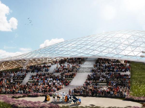
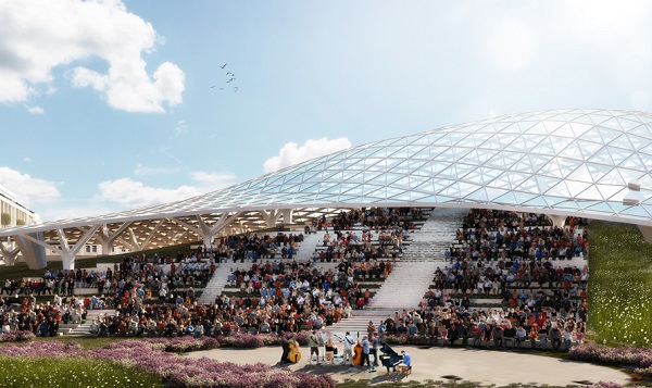
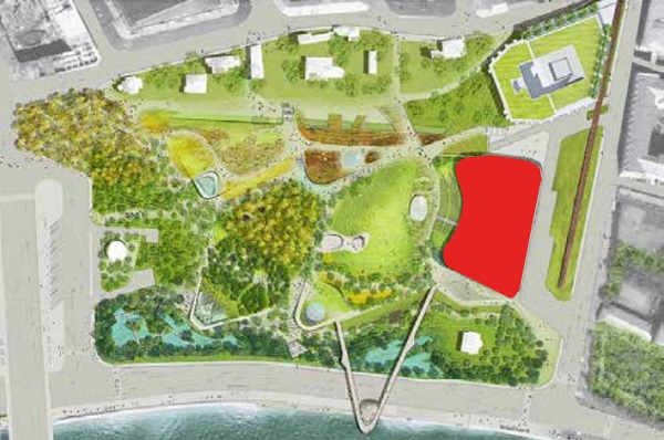
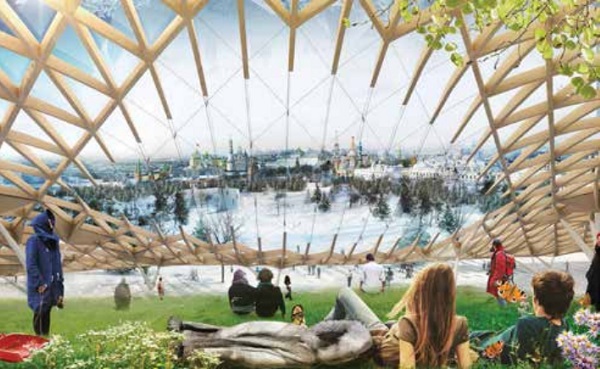
This paper will describe the design, detailing, testing and construction of structural glass beams as part of load bearing grid shell structure in the newly built Zaryadye Park in Moscow, Russia, situated short distance from Red Square and the Kremlin. Glass beams (72 in total) are fixed into the main steel grid shell structure measured around 120m long by 60m wide and measured around 3m long by 0.2m deep.
Glass beams were designed to accommodate extreme weather conditions with snow drift loads of up to 350 kg/m2, as well as differential movement of the main structure which required sophisticated analysis with more than 100 load combinations as well as full scale testing to gain approvals from the authorities.
Due to lack of legislation on use of structural glass in Russia, so called “special technical standard” was created with our help to cover technical aspects of glass and it’s performance, which formed part of approval documents.
Design
3.1 Concept
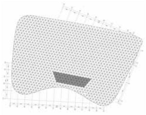
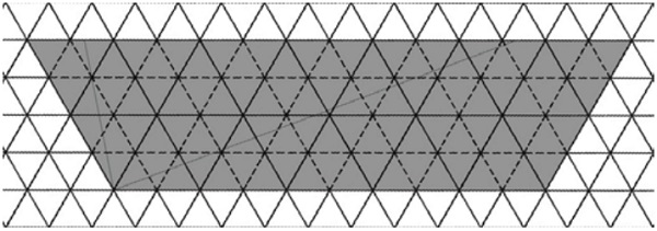
The grid shell structure was designed to follow the curve of artificially created hill as an open structure (not enclosed), hence subject to thermal movements as well as snow loading and wind. The main structure is comprised of structural steel elements of approximately 3m long and 300mm deep.
However in certain locations clear less obstructed views were required, hence more transparency in the structure was necessary. Initially glass clad cable structure was proposed by the architect, however due to significant snow drifts high prestress forces were required which proved to be difficult to achieve hence different solution needed to be found.
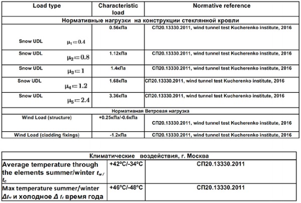
3.2 Design loadings
Scaled model of entire project was wind tunnel tested to ascertain wind loads and possible snow drifts associated with that. Resulting loads are shown below:
In total there were 19 load cases which included: 3 cases for dead load, 5 variations on snow, 9 load cases for wind and 2 cases for the thermal movement. All those load cases generated over hundred different load combinations.
3.3 Load combinations used
Load combinations taken in accordance with Eurocode 0&1:
ULS: 1.35Gk + 1.5 Qk1 + 1.5ψ0 Qk2
SLS: Gk + Qk1 + ψ0Qk2
3.4 Glass selection
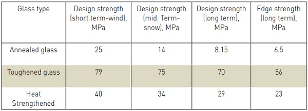
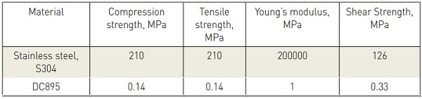
Based on draft version of European standard for use of glass in structures, following design values were adopted for this project, see table 1&2 on the left: Glass beam thickness was adopted as 5x10mm toughened glass laminated with PVB interlayer each 1.5mm thick.
3.5 Other materials used in the construction
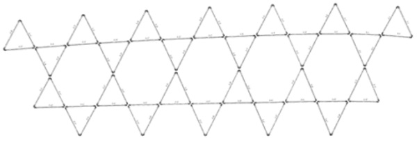
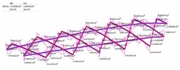
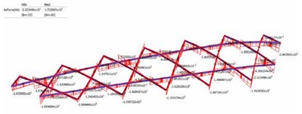
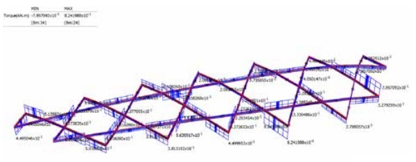
3.8 Computer modelling
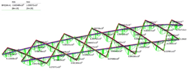
Node coordinates were imported from the main engineer’s model with associated deformations under individual load cases. Node deformations were combined with individual loadings for each glass beam and then analysed. Over 100 different load combinations were generated and analysed.
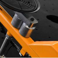
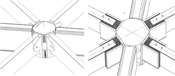
3.9 Bracket design
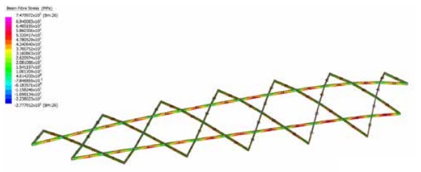
Initially, bolted connection was assumed however from mode detailed analysis and assessment it was clear that relatively rigid bolt connection details causing glass overstress in various locations. Hence softer, more flexible joint details was required.
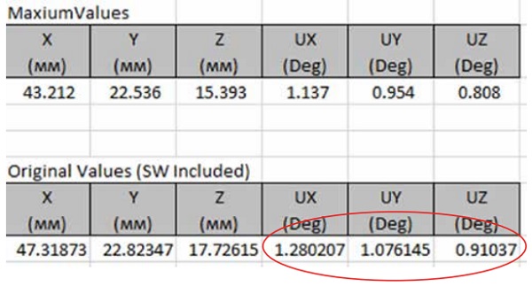
Detailed analysis of node deformations in glass fixing points was carried out and summarized in Fig 13 on the right side. Based on this, nodes are predicted to be rotating approximately 1 degree around each axis. One rotation requirement was established, joint stiffness could be calibrated to minimize stress concentrations in glass.
To model and predict stresses within flexible joint, non-linear solid modelling was carried out using Mooney-Rivlin behavior model and stress strain curve tabulated data based on information from silicone manufacturer. Adopted model has shown silicone behaving within allowable stress range, see fig. 14 on the right side.

Testing
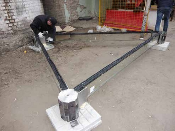
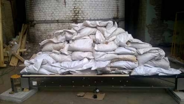
4.1 Full scale mock up
Due to unprecedented nature of the project in this country, it has been decided that full scape testing mock up is necessary. The tests were carried out in the Glass Institute facilities in Moscow, on the 26th April 2017.
Production
5.1. Glass production
Glass production was carried out during the course of April 2017 by Modern Glass Ltd, Chelyabingks, Russia with installation due to start on site in May-June 2017.
Conclusion
In conclusion, this project is our first experiment with use of structural glass beam element in grid-shell type construction which in our view has a potential to be scaled up.
References
Institution of Structural Engineers: Structural use of glass in buildings (1st ed). London, IStructE, (1999)
Institution of Structural Engineers: Structural use of glass in buildings (2nd ed), London, IStructE, (2014)
G. Vasilchenko-Malishev, Malishev Engineers