SUMMARY
Spandrel glazing has developed to a stage where more efficient insulation can generate higher thermal stresses than can normally be resisted by heat strengthened (HS) glass on which ceramic enamel (frit) has been applied.
This paper details: the evolution of spandrel glazing; examples of unexpected breakage; a finite difference method for computing thermal stress; a discussion of possible causes of the weakening of heat treated (HT) glass with applied ceramic enamel; and suggested design changes to eliminate this breakage.
EVOLUTION OF SPANDRELS
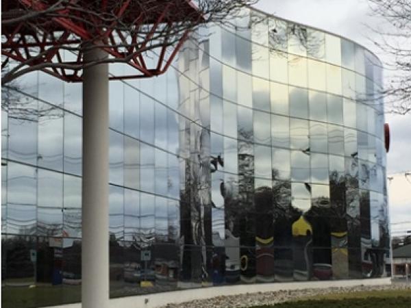
Early (circa 1970) Curtain Walls often had high reflectivity coatings with low light transmission (around 10 %) so, apart from the effect of coating variations, single glazed spandrel glass (covering the edges of the floor slabs) did not look much different from the adjacent double glazed vision glass, and the desired uniformity of exterior daylight appearance was readily achieved without too much concern over what was behind the spandrel glass.
Figure 1. First Surface Silver Color Coated Vision and Spandrel Glass. ̴25 Years Old.
Figure 2. Second Surface Reflective Coated Vision and Spandrel Glass.
OPACIFICATION
Single glazing, with an organic paint opacifier on #2 surface (to make it opaque), was used for spandrel glazing when the higher daylight transmission of the glass would allow unwanted vision of the insulation or floor slab edges. These paints sometimes bubbled and peeled with age. Remember the first molecule of paint which the sun’s UV strikes in this configuration is the same molecule that is trying to hold the paint to the glass.
Black stick-on, opacifier scrim films, using water based or solvent based adhesives, were more reliable but still gave rise to occasional adhesion and bubbling problems.
Using ceramic enamel (often popularly, but inaccurately, called “frit”) on the #2 surface of spandrels avoided the opacifier durability issues. Note: Ceramic enamels on glass have 3 components: carrier medium of light oil; non-soluble inorganic pigment; and low melt temperature glass powder or “frit”.
This solution did not always work with reflective coated glass because either the reflective coating was not compatible with the enamel, or the reflectivity was changed by the application of the enamel.
High thermal stress from solar radiation inevitably required heat treatment of the spandrel glass to resist breakage.
The use of fully tempered (FT) glass, risked rare spontaneous breakage due to gradual expansion of nickel sulphide inclusions. Scrim backing could be applied behind the opacifying enamel to retain glass pieces from any breakage.
The City Building Code of Toronto, Ontario, Canada, required scrim backing to withstand a 4 psf (pounds per square foot) (0.2 kPa) load] to FT spandrel glass after some FT spandrels broke and could have fallen out of their framing.
Another solution to retaining broken HT glass was to use HS glass which would not break into small particles and would therefore be less likely to fall out of the opening.
Remember: Design glass not to break, but also design it so that the consequences of unexpected breakage are acceptable.
SHADOW-BOX SPANDRELS
The use of “Shadow-box” spandrel construction allowed an external viewer to see through the spandrel glass, reflective-coated or not, to a closed, darkened area behind the glass. The use of a dark, non-reflective material behind transparent spandrel glass (no opacifier on the glass), gave a better complementarity of appearance, and a better visual match between the vision and spandrel areas. Reflected light from within the box was effectively eliminated by using dark materials such as:
- Black tar Paper over the insulation
- Three layers of Fiberglass insect screen
The very high temperatures (>100 °C (212 °F)) generated in a closed, insulated shadow box could soften and melt foam plastic insulation. See Figure 3 below.
Figure 3. Foam Plastic Insulation with Softening Point of 104 °C (220 °F)
Photo Credit: Tim Moore
High shadow-box temperatures could readily generate volatile vapors from organic materials used in the box, such opacifying tar paper, insulation binders, etc. Those vapors could condense on the cooler glass, creating visible deposits. Figure 4 below is interesting in that it shows much greater visibility of condensed vapor deposits on the middle and right hand lites which are in the shade from another building, compared to the sunlit lites on the left side. Under equal lighting the deposits on all lites were almost equally visible.
Figure 4. Condensed Vapor Deposits visible on Spandrel Lites
Fiberglass insect screening gave little outgassing but could still allow occasional water vapor condensation on the glass. Frequent occurrence of such condensation readily caused glass staining with associated accumulations of visible deposits.
IG SHADOW-BOX GLAZING.
A better visual match between vision and spandrel was realized by using Heat Treated Insulating Glass (IG) instead of single glazed spandrels, with low-e and reflective coatings exactly matching the vision glass.
Figure 5. Gold Color 2nd Surface Coated Insulating Glass (IG) Vision and Spandrels.
(Note difference in exterior reflectivity resulting from different interior treatments – see Fig. 6)
Figure 6. Gold Color 2nd Surface Coated, Vision and Spandrel IG Units. Viewed from Interior.
It should be noted that a single coating of enamel was usually insufficient to block all transmitted light when viewed from the interior. See Fig. 6 above.
IG Shadow-boxes with opaque ceramic enamel frit on #4 surface proved to be more thermally stable and avoided visible condensation issues. The use of sealed insulating glass requires a high performance edge seal to withstand the high temperatures of in-service spandrels: >212°F (100°C).
Note: ASTM 2188 IG Weathering Test only uses 140°F (60°C) maximum temperatures.
FINAL SPANDREL ITERATION:
IG HS Ceramic Enamel #4 Surface, using HS glass instead of FT to avoid possible spontaneous FT breakage, appeared to be the perfect design.
UNEXPECTED BREAKAGE
But we now find that this particular configuration has resulted in the unexpected thermal stress breakage that this paper details. The authors are personally aware of, or have site investigated, about 20 different buildings with such breakage in Canada and in the USA.
Figure 7. View of Broken Inner Lite of an IG Spandrel from the Exterior
Figure 8. View of #4 surface of broken IG Spandrel Glass with Ceramic Enamel.
Fgure 9. Fracture Origin in Enameled Surface
Figure 10. Two Halves of a Fracture Origin Placed Back to Back. Origin is about 12 mm from Cut Edge.
The fractures for the broken spandrels described above were examined in detail.
The breaks were deemed to have been caused by high Thermal Stress because:
- No glass damage at fracture origin
- No glass or enamel inclusions at fracture origin
- Origin not at a high stress area for uniform lateral load
- Origin not at glass edge indicating no handling or installation issues
- Small mirror radius indicating high stress
GLASS BREAKAGE.
Glass breaks because the applied load (thermal or other) exceeds the glass strength. This investigation endeavored to determine which was the prime cause.
Figure 11. Schematic of Strength / Stress Relationships
The solar induced thermal stress is shown in red in the schematic above. Solar load typically creates low level compressive stress in the central area of a plate, and a high tensile stress around the edges.
The quenching air flow of the HT process produces stronger glass at the edges where the forced convection cooling is greater.
Breakage can be expected when the tensile load (red) is greater than the HT glass strength (green).
THERMAL STRESS LOAD
How Much Thermal Stress is generated in IG spandrel glass?
With no shadows, and single glazed spandrels in rubber gasket glazing, sunlit glass can be fairly uniformly heated, and it is even occasionally possible to use annealed glass. But for typical IG curtain wall glazing with aluminum frames, even with exposed glass edges, when structurally silicone glazed to thermally conductive aluminum framing, the in-service temperature differentials encountered within the spandrel glass usually become too large for annealed glass. Heat treatment is then needed to strengthen the glass.
Finite Element Analysis (FEA) can be used for a detailed determination of the thermal stresses. A simple Spreadsheet Finite Difference Method for calculating Thermal Stress in Spandrel Glass, is shown here:
The Microsoft Excel program allows recursive or self-referential loops, by switching it to manual calculation by clicking:
File / Options / Formulas / Calculation Options / Manual / Enable Iterative Calculation.
Set “Number of iterations” to 32,000 and “Maximum change” to 100.
Example: Take a plate with known temperatures of say 10o at the left edge (shown in red in the plane view below), bottom edge at say 5o (shown in tan), and the top right corner at 0o (shown in blue). Compute the unknown temperatures of remaining cells by taking each as simply the average of the temperature of the 4 cells to the North, East, South and West of it. e.g.
Tcenter = (Tn+Te+Ts+Tw)/4. (Note: the top row of cells is the average of 3 adjacent cells: Tcenter = (Tw+Te+Ts)/3; similarly, the formula for the right hand column cells is T = (Tw+Tn+Ts)/3.
(You need to add an iteration counter and a conditional check on each computed cell, using a start or clear cell, to reset all the cells to zero at the start of each new series of calculations)
Figure 12.
Key F9 to perform 32,000 iterations at a time. After many iterations you get the following: (Use “Conditional Formatting” to put values between 3 and 7 Degrees in pink).
Figure 13.
To do this in more detail for the edge of a typical IG spandrel (Solar control Low-E coating on #2 surface, opaque grey ceramic enamel on #4 surface) with structural silicone sealant (blue) to an aluminum frame (red), shown here in section view through the IG unit and framing. The aluminum framing, and IG spacer, are shown in red:
Figure 14.
Run LBNL Window 6 program, with sun, zero wind and appropriate air temperature for the glass in question to get the U-Factor, the uniform, steady-state center-of-glass temperatures, and hence the air to glass heat transfer coefficients by calculation. The Window 6 method only gives the center of glass values. It does not give the glass temperature gradients at the edges which create stress and potential breakage.
The formula for the calculated cells uses the steady state condition:
Total Heat Flow In + Total Heat Flow Out = 0
The formula below allows the different thermal conductivity (°C) for different adjacent materials to be added.
To calculate the resulting steady state temperatures use the iterative procedure given above:
Figure 15.
Plotting these resulting equilibrium glass temperature values from about a million iterations (key F9 about 30 times) of the finite difference program shows the inner lite (blue line) has the greatest temperature differences.
Figure 16.
Glass stress is approximated by: Stress = E x Alpha x Delta T
Where: E = Glass Modulus of Elasticity
Alpha = Coefficient of Thermal Expansion
Delta T = Temperature difference
Results for the example above show the greatest stress in the inner lite (upper blue curve) of about 10.4E6 x 4.6E-6 x (270 – 120) = 7,176 psi (49.4 MPa)
HT glass is needed to resist this thermal stress.
The results of such a thermal stress analysis usually suggest that HS glass should be strong enough but we have seen in practice that this is not necessarily so.
STRENGTH OF HEAT TREATED ENAMELED GLASS
The breaks seen to date all involved HS IG insulated spandrels, from various fabricators, with ceramic enamel frits of different colors, from different sources, on various substrate glasses. Most had a low-e coating on surface #2 of the IG unit.
Break origins were always on the enameled surface (#4) of the glass (see Figures 8 - 10), despite both surfaces of the inner lite suffering essentially equal thermal stress when in service. The break origins were located about ¾” (20 mm) in from a cut edge showing that the weakening was not a function of the cut edge condition (edge quality, seaming, etc.). In no case was glass or frit damage seen at the break origin. This may be because the air flow during heat treatment gives greater quenching and greater skin compressive stress (green) around the glass edges.
STRENGTH TESTS OF HT ENAMELED GLASS
Unpublished 4 point bending tests to failure of 150 samples of HS and FT glass, as used on one recent North American problem building, with and without enamel, show a large reduction in the 3-second equivalent mean breakage stress (approximately 60%) with the enameled surface in tension. See Figure 12.
Figure 17. Cumulative Probability of Breakage versus 3-Second Equivalent Fracture Stress for HS Specimens.
Only 36% reduction in the 3-second equivalent breakage stress occurs at the nominal 8 in 1000 probability of breakage level generally used for design purposes, Figure 18.
Figure 18. Enlarged View of Cumulative Distribution Function in Figure 17.
Similar tests with FT glass show around 40% reduction in the 3-second equivalent mean breakage stress (Figure 19), and a 21% reduction in in the 3-second equivalent breakage stress at 8 in 1000 probability of breakage level (Figure 20) when the frit side is placed in tension.
Figure 19. Cumulative Probability of Breakage versus 3-Second Equivalent Fracture Stress for FT Specimens.
Figure 20. Enlarged View of Cumulative Distribution Function in Figure 19.
HS Mean Strength – >50% Load reduction
HS 8/1000 Design Strength – 36% Load reduction
FT Mean Strength – 35% Load reduction
FT 8/1000 Design Strength – 21% Load reduction
The inevitable conclusion is that ceramic enamel can weaken HT glass when exposed to thermal or uniform pressure loads.
It is noted that German (DIN 18008) and European (EN 12150) standards quantify a weakening of 36% and 38% for HS and FT glass respectively, under uniform load.
Weakening of FT glass with ceramic enamel under impact test, with a steel ball impacting the enameled surface, has been anecdotally known among the automotive glazing industry for some time.
HOW CAN CERAMIC ENAMEL WEAKEN HT GLASS?
The exact mechanism is not known but plausible mechanisms to consider are:
- The inhomogeneous nature of the enamel could have less strength than that of the underlying homogenous float glass. A crack starting at lower stress in the weaker enamel could possibly propagate readily into the intimately bonded glass substrate.
- If the enamel has a higher modulus of elasticity it would be more stressed than the substrate glass when bent and so the assembly could crack earlier than expected.
- Somehow, chemically or mechanically, the frit damages the glass surface.
- During quenching in the heat treatment process, an enamel with a different emissivity than plain glass would alter the heat flow from the side to which it is applied.
CONSEQUENCE OF STRENGTH REDUCTION
The reduced glass strength results seen with ceramic enamel under thermal stress loads in service, and in laboratory bending tests, clearly show a reduced load capacity for both thermal stresses and wind induced bending stresses. While no glass breakage has been reported in service for HS glass with ceramic enamel under wind load, it is important that the above strength reductions be recognized for both thermal and wind load situations.
CONCLUSIONS
Unexpected thermal stress breakage of IG insulated spandrel glass has occurred on a number of occasions because ceramic enamel frit, on #4 surface, has weakened the Heat Treated inner lite. Such breakage may avoided in future by using FT glass for the inner lite.
The wind load resistance and impact resistance of ceramic enameled glass (types FT, HS and Annealed) must be also carefully evaluated to allow for associated possible strength reductions.
RECOMMENDATIONS
While there may well be some ceramic enamels with differing properties and hence more or less likely to weaken HT glass, at this stage they are not publicly known or available.
In the meantime, with European standards requiring recognition of the issue, and significant breakage being experienced in a number of North American buildings, the following actions are strongly recommended to prevent this unexpected breakage:
- Do not use HS glass with applied ceramic enamel as the inner lite in IG insulated Spandrel units unless permitted by a detailed thermal stress analysis.
- Consider using FT glass for the enameled lite of the IG unit.
- Consider Heat Soaking the FT enameled glass for the enameled lite of the IG unit if spontaneous breakage is a concern. Spontaneous breakage of the inner FT lite should not be critical if the IG unit is vertical because sufficient glass particle retention would be given by typical 4 side structural silicone or wet adhesive framed glazing. (Heat Soaking of samples from the batch of FT glass, rather than every lite, can be done on a statistical basis if the results of such tests are carefully monitored for added security against spontaneous breakage).
- If thermal stress analysis shows that non-ceramic coated HS glass is strong enough then consider opacifying the #4 surface with other materials which would not be expected to alter the HT glass strength. Such materials must be demonstrated to be effective and durable under the expected harsh operating conditions of typical spandrels.
- Consider reducing the allowable maximum stress (both from uniform wind or snow load, and from thermal loads) by about 40 % when ceramic enamel is applied to HT glass, unless other test data is available.
- Impact resistant glass is deemed to be “Safety Glass” when it either breaks into very small pieces, or does not break, under a specified impact load. Note that the application of ceramic enamel to FT glass may alter the performance under the latter qualifying condition.
- Test the strength of re-annealed bent enameled glass
''Unexpected Spandrel Breakage" paper Chris Barry wrote with Prof. Scott Norville of Texas Tech. University. The paper was first presented at the IGMA (Insulating Glass Manufacturer's Alliance) meeting in Feb. 2015, St. Petersburg, Florida.
Chris. Barry
ChrisBarryGlassConsultant@Gmail.com
Cell: 419 283 8584
H. Scott Norville, P.E., Ph.D.,
Scott.norville@ttu.edu
ABOUT THE AUTHOR:
Chris Barry is a professional engineer (mechanical) from UCD, Dublin, Ireland, with 46 years’ experience in float glass manufacture, fabrication and installation, with Pilkington NA / NSG in the USA and Canada.
He is a frequent presenter at GPD, GANA (Glass Association of North America), IGMA (Insulating Glass Manufacturers Alliance) and other fabrication, design and installation groups.
He has retired from full time work and is now an independent consultant, in Perrysburg, Ohio, USA, applying his lifetime of experience to improving architectural glass applications.
He can be contacted at: ChrisBarryGlassConsultant@Gmail.com

