Source:
Challenging Glass 7
Conference on Architectural and Structural Applications of Glass
Belis, Bos & Louter (Eds.), Ghent University, September 2020.
Copyright © with the authors. All rights reserved.
ISBN 978-94-6366-296-3, https://doi.org/10.7480/cgc.7.4548
Authors:
Jordi Alcaine
Peter Lenk
Ed Forwood

The use of Structural silicone glazing (SSG) systems in large commercial glazed facades is well established in current practice, mainly due to the architectural aspiration of having a continuous smooth glass surface across the building elevation. Enhanced thermal and security (blast) performance are typically listed as an advantage for this particular type of systems.
SSG façade systems are structurally complex due to the fact that multiple load-paths can be identified within the system. It is accepted as good practice to detail façade panels so that the dead load of the glass is not carried through the structural silicone. But can this be achieved in reality? The aim of this paper is to identify and discuss challenges with the assumption that the SSG is isolated from the glass self-weight and provide a better understanding on the complexity of SSG systems.
The influence of stress/strain and creep due to thelong-term load on the system capacity will be investigated. Some degree of long term loads are usually present due to detailing and real system behaviour. Real project examples will be used to identify opportunities for improvement and findings will be summarised at the end of the paper.
1. Introduction to structural silicone glazed systems
Structural silicone glazing (SSG) has been used in the building industry for more than 50 years, having its origin in 1965. Since 1970-1990 international standards ETAG002 and ASTM C1401 regulate the design of SSG joints bonding glass panels to metallic framing via simplified equations. These standards effectively provide calculation methods for flat vertical glass units with rectangular shape, bonded along all sides to load bearing profiles, experimenting limited deflections and subjected to wind load, dead load and temperature variations.
The use of structural silicone has grown significantly in lieu of mechanical connection in recent years due to multiple advantages that this well stablished technology offers. Structurally bonded systems facilitate the architectural aspiration of having a continuous smooth glass surface across the building elevation while improving thermal, acoustic and blast performance. The use of this type of systems also offer other advantages such as reduction in the peak glass stresses due to the concentrated glass supports.
In the last few decades, available technologies have developed significantly in the façade industry, increasing the complexity of the projects and challenging the design of SSG joints applied in new system configurations and load conditions. The use of FEM analysis offers designers a, reliable and accurate method to predict results on the mechanical behavior of adhesive glass-metal connections.
2. Real behavior of structural silicone glazed systems
2.1. Structural silicone glazing on façade engineering applications
Structural glazing systems in façade engineering applications utilise a silicone adhesive to attach glass to metal frames (typically aluminum) or to bond two pieces of glass. Structural silicone joints can be designed to ensure that dynamic loads (i.e.wind, barrier) and permanent loads (i.e. sw) can be safely transferred from the glass to the structure of the building via the structural sealant. Although, structural silicone can be used to resist permanent loads, SSG is not typically used for this purpose as the strength of the sealant under permanent loading is assumed by published guidance to be 10 times smaller than the strength to resist dynamic loads.
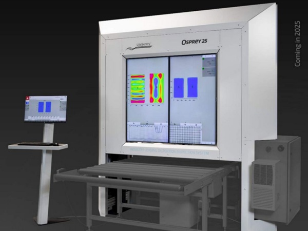
Quality control is the most critical element to ensure that the sealant performs. Therefore, SSG is typically applied in the controlled environment of a production facility, where external factors such as dust, temperature and relative humidity can be controlled and monitored. SSG manufacturers have specific procedures and recommendations that must be followed to ensure proper adhesion, curing and joint fill.
Façade consultancies tend to limit the use of SSG on the job site in their specifications due to the difficulties to control the environment (dust, temperature, humidity) and to monitor the QC. Therefore, the use of structural silicone is more extensive in unitized facades, where the glass is bonded and cured in the controlled environment of a factory.
When designing structurally glazed unitized systems the effect of permanent loads (glass self-weight) is typically ignored. It is assumed that structurally glazed systems behave in the same way as capped systems. In capped systems the glass pane bears directly onto the shoes, then the load is transferred from the transom up the mullions through the corner mullion/transom fixing and finally the dead load is transferred back to the main structure through the bracket. Is this load path valid though for SSG systems? Do structural glazed systems behave as capped systems under dead load? Is this the only dead load path available within SSG system? What happens under building frame movements?
In the following chapter the behavior of structurally glazed systems will be further explored. To do so, the stage analysis will evaluate the structural silicone glazing from the assembly in the factory until its final position in the building.
2.2. Structural behavior of SSG systems under gravity loading
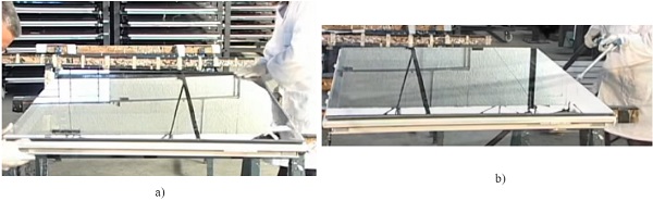
In order to understand the behavior of SSG systems, firstly the installation sequence of the structurally glazed unitized panel in the factory is investigated:
The installation sequence for the curtain wall units assembled in the factory comprise the following steps:
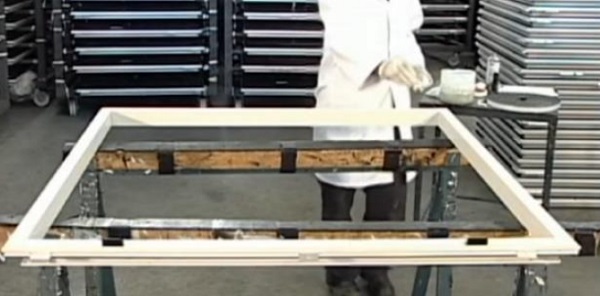
- Step 1 -The frame is placed horizontally on a working bench
- Step 2 -The glass is installed on the frame.
- Step 3 -Frame is cleaned, primed and the structural silicone glazing is applied
- Step 4 -Once the silicone is cured, the unit is moved to the stockage area.
To investigate the real behavior of the unitized panel under gravity loading when the panel is lifted and removed from the working bench (see step 4), a FEM model has been built and a non-linear analysis carried out. To do so, the panel has been modelled with the structural analysis software “Strand 7”:
- Mullions and transoms have been modelled as 1D elements
- Glass and spandrel panel as 2D plate/shell elements
- SSG and glass shoes as connection elements (i.e. 1D elements defined using the shear and axial stiffness of each element)
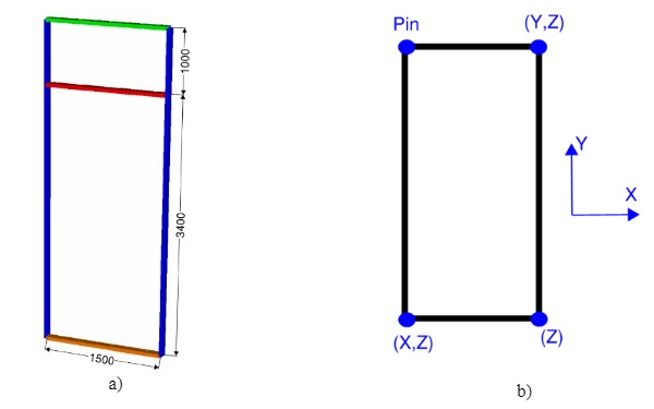
- Geometry: a 4400mm high (containing a 1000mm spandrel panel) and 1500mm wide has been modelled
- Boundary conditions: The unit is assumed to be top hung on the top corners and bottom restrained on the bottom corners
- Loading: the analysis will be carried out under gravity loading only
- Type of analysis: non-linear static
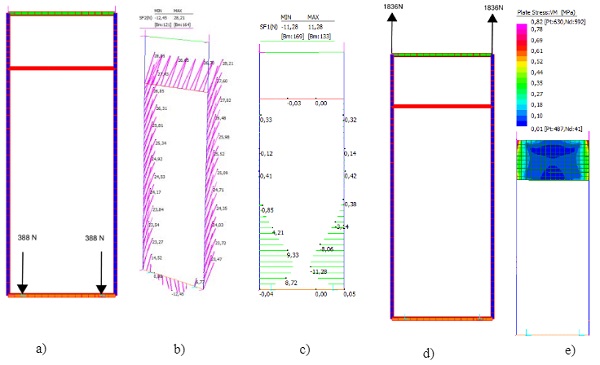
The result of the analysis shows that Dead load of the glass is shared between the silicone and the supporting shoes. The exact distribution will vary depending upon the stiffness of the silicone, the stiffness of the shoe detail, the bending stiffness of the transomand the initial tightness of fit of the glass to the support detail.
Vertical deflection of the transom will result in some inward bowing of the mullions (i.e.bending on the mullion’s weak or minor axis) and this will result in some in plane stresses within the mullion silicone. It will also affect the vertical stress in the silicone to the transoms both at the top and bottom of the glass plane.
2.3. Structure/façade interaction and influence on structural silicone
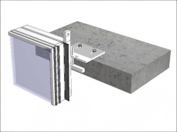
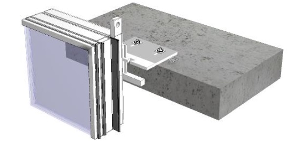
The next step to understand the real behavior of structurally glazed unitized systems, is to analyze the behavior of the panel once it is installed in the building. As a reference for this exercise, a unitized façade with a “hung & sworded system” will be investigated.
Hung & sworded systems upon installation hang off brackets to both sides but under building movements will lift off either the left or right-hand brackets. Under this scenario the panel hangs from one bracket from the slab above and has its dead load eccentricity stabilized by a restraining “sword” connected to the panel below. Such a system is advantageous to minimizing the joint requirements between adjacent mullions.
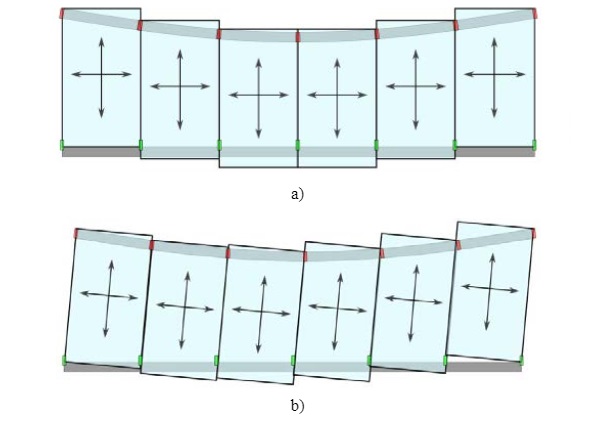
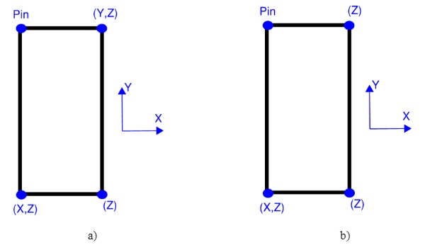
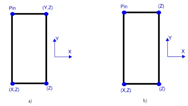
The boundary conditions for a “hung and sworded” system can be described in two different stages as follows:
- Evenly supported stage–representative of the initial state after installation in the building when the panel hangs from both brackets.
- Racked stage–representative of the movement accommodation interpretation of “hung & sworded system”. The panel is held off one bracket and restrained in plane by one of the swords.
To capture this onto the FEM model described on point 2.1, a staged analysis was carried out to investigate how the modifications on the support conditions affect the structural silicone.
The following stages were defined on the Strand 7 model:
- Stage 1 - Evenly supported stage submitted to gravity loading
- Stage 2 – having stage 1 as birth state and modifying the support conditions as defined above
Results for stage 1 can be found on point 2.2, on the following lines results for stage 2 are summarized:
The ‘loss’ of one support re-routes the dead load path for one half of the glass weight of the panel in accordance with a number of load paths:
- Through the unsupported side shoe or unsupported side structural silicone up the mullion and into the spandrel back panel. Then though the spandrel panel in shear which in turn will create minor axis bending in the mullion and a step in axial force in the mullion. It would also create an in-plane push pull at the top and bottom supports due to the dead load eccentricity.
- Though the structural silicone on the supported mullion as a vertical shear with an associated in plane shear on the structural silicone between mullion and glass
- Through the supported side shoe as a vertical load together with a horizontal shear in the silicone to the top transom or in plane shear on the structural silicone between glass and the supported side mullion – and some in plane shear in the silicone to the unsupported side mullion.
2.4. Structural silicone glazing fabrication constrains
As described above, permanent stresses are locked in the structural silicone due to the glazing and bonding sequence followed in the factory during the glass assembly and because of the real behavior of unitized systems hence, the effect of permanent stresses on silicone cannot be neglected and should be accounted for during the design phase.
Firstly, as the units are bonded and cured in horizontal position, when the façade panel is lifted the glass SW is distributed between the shoes and the structural silicone (load share between glass shoes and structural silicone is dependent on the stiffness of both components) hence, factory assembled units will have permanent stresses locked into the structural silicone due to the assembly process.
There are multiple load paths available for the dead load within structural glazed systems, the real behaviour of SSG systems is also dependent upon the support strategy (i.e. hung, hung-sworded) and as such, the singularities (different support conditions) of each system should be analysed and the magnitude of the permanent stresses locked into the structural silicone estimated.
The stiffness of the silicone joint may also affect other components of the unitized system. For instance, in a “hung and sworded system” during the racked stage, the amount of glass SW going onto a glass shoe and the brackets can be greater than 50%. Designers should evaluate with due conservatism the amount of permanent loading going onto these components so that they can be designed accordingly.
As justified above, it is very difficult to avoid introducing permanent stresses on structural silicone, designers must understand the complexity of structurally glazed systems and their singularities. Permanent stresses locked in structural silicone as a result of the assembly process and the real behaviour of unitized systems, have to be estimated and evaluated as part of the design. In the following chapter amore detailed example will be used to estimate and evaluate the permanent stresses onto structural silicone.
3. Real project examples
The worked example will be based on a “hung & sworded” unitized façade, structurally glazed.
3.1. Geometry
Typical unitise glazing panel with width of 1.5m and height of 4.4m was analysed with aluminium framing members.
3.2. Connection elements
3.2.1. Glass shoes
As the shoe has a tapered section (varying thickness from 3 to 5mm) in order to get a more accurate estimate on the stiffness of the shoe, a local FEA model has been used.
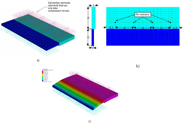
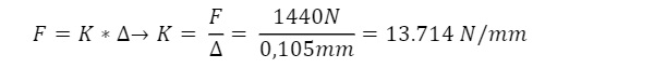
A nominal load (evenly distributed between all the nodes) on the dark-blue area was applied and by using Hooke ́s law the spring stiffness of the shoe was derived.
3.2.2. Structural silicone glazing
The spring stiffness has been derived assuming the following material properties as given in [1]:
- E = 4 MPa
- G = 0.67MPa
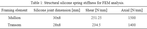
It is typical that material stiffness is derived as mean value, while strength represents 95% percentile. Safety factor related to the short-term strength varies between 6 and 4, typically depending on the complexity of the analysis carried out. The spring stiffness of the silicone used in the model have been derived in the table below assuming that the spacing between elements is 100mm.
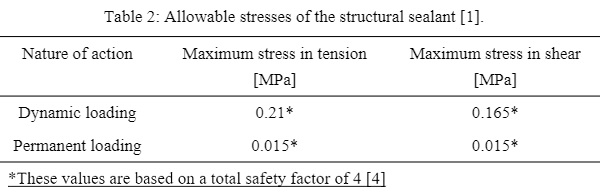
Structural silicone allowable stresses:
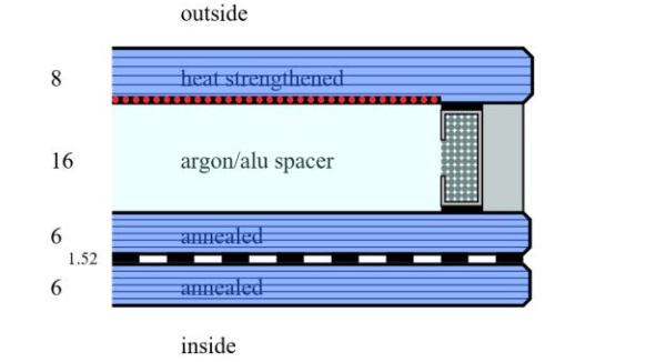
3.3. Glass thickness
The glass build-up of the panel bonded onto the frame is illustrated in the following figure
3.4. FEA modelling
To evaluate the amount of permanent stresses onto the glass, a non-linear stage analysis was carried out. The following stages were defined:
- Evenly supported stage – representative of the initial state after installation in the building when the panel hangs from both brackets.
- Racked stage – representative of the movement accommodation interpretation of “hung & sworded system”. The panel is held off one bracket and restrained in plane by one of the swords
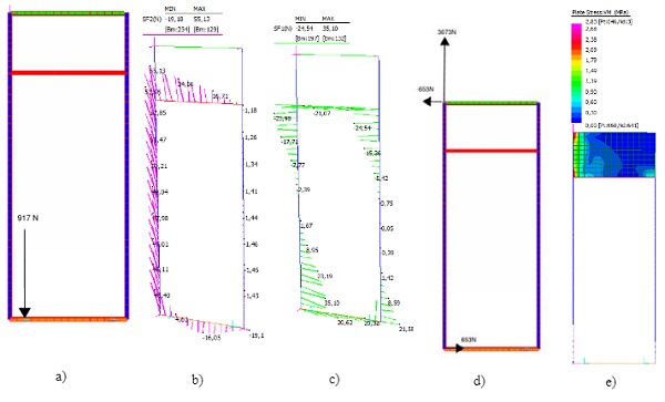
3.5. FEA load diagrams
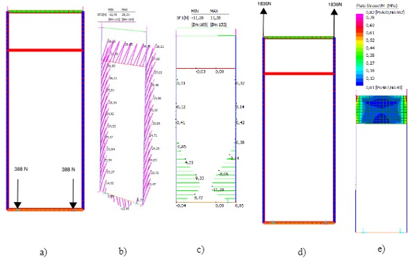
3.5.1. Stage 1-the panel is evenly supported from both brackets
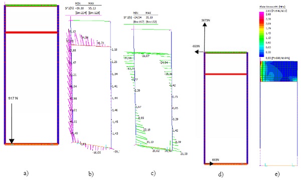
3.5.2. Stage 2 - the panel is racked
3.6. Results
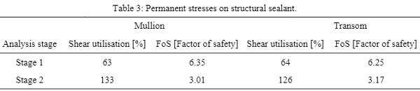
3.6.1. Permanent stresses on structural silicone
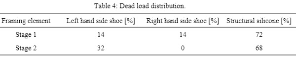
3.6.2. Glass self-weight distribution
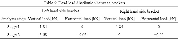
3.6.3. Self-weight distributionon brackets
3.7. Worked example summary and conclusions
- The unit analyzed under the evenly supported scenario (stage 1) has a safety factor on the structural silicone bigger than 4 hence, the stress intensity is relatively small.
- Under the racked scenario (stage 2) structural silicone has a safety factor < 4which means that structural silicone might creep over time. Any creep in the silicone will reduce the stress in the silicone as other load paths become available to carry the load.
- The relative stiffness between the glass shoes and the structural silicone distributes 72% of the glass self-weight onto the structural silicone
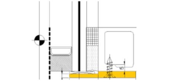
- Under stage 2 the entire glass self-weight is supported in one bracket. Any creep in the silicone may lead to movement of the glass plane relative to the frame should the slabs be in a deflected state as illustrated in figure 6. Long term movements are hard to predict given a lack of industry knowledge relating to the creep performance of structural silicone.In the next chapter the adequacy of using simple material models to verify structural silicone bite will be explored.
4. Structural silicone behavior
4.1. SSG analysis using advance hyper-elastic material models
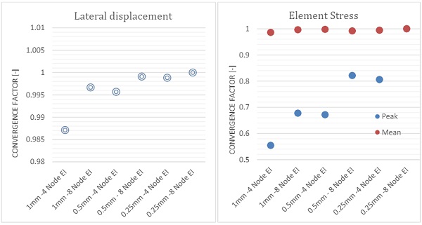
As discussed in the previous chapter, first principles and simple material models are typically used in everyday engineering practice to verify adequacy of the silicone bite. In this paper, we conducted parametric nonlinear numerical analysis, where we studied influence of the aspect ratio on stiffness and peak stress in the silicone join. Shear and tension load was considered only. An initial mesh convergence test was carried out with mesh size of 1mm, 0.5mm and 0.25mm to investigate influence of mesh density on results. All elements were quadrilateral with aspect ratio of 1, both linear and quadratic element were examined.
From results presented on graph 1 a stiffness variation within 1.5% was observed with fast convergence after the first mesh iteration. Silicone stress convergence is presented on graph 1b. Mean body stress followed similar pattern with variation within 2%, however peak stress variation was significant with almost 40% variation. An 8-node quadrilateral quadratic element with mesh density of 0.5mm were selected, as an acceptable compromise, for further studies in this paper.
Comparative study was carried out where structural silicone was modelled with selected material models. All material models were extracted from the published literature related to the behavior of the hyper-elastic materials, [2],[3], [4], [5], [6], [7],. Numerous recommendations were obtained during our literature review.
Material models considered in this study:
- Linear elastic material with E=4MPa, G= 0.67 MPa, v= 0.49, (It shall be noted that two different material models are required if tension and shear are assessed)
- Neo Hookean model with C= 0.67 MPa,
- Mooney Rivlin model with C1=0.33 MPa and C2=0.005 MPa,
- Mooney Rivlin model with C1=0.42 MPa and C2=0.054 MPa, (constants calculated by curved fitting of stress stain curve by authors)
- Ogden with C= 0.71938 MPa, α= 1.9225,
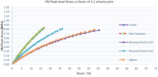
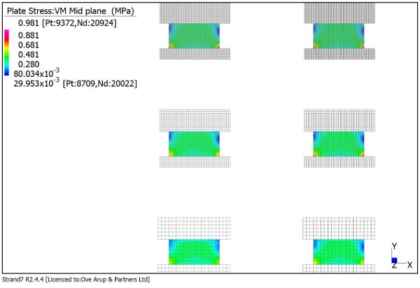
Numerical samples with aspect ratio of 1:1, 1:2 and 1:4 were also analyzed to investigate influence of the aspect ratio on the stress and stiffness. Two loading conditions were considered tension and shear independently, no interaction was investigated in this paper. Further studies will be required to analyse joints subjected to tension and shear. Load was applied uniformly over the silicone joint with equal stress intensity per silicone width. Results as presented below are for engineering tension stress of 0.6 MPa and 0.3MPa in shear as derived from first principles. We would expect 15% axial strains (displacement of 1mm) and 44% shear strains (displacement of 3.1mm).
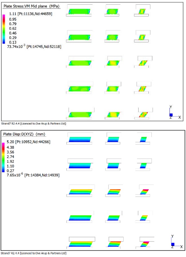
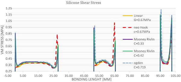
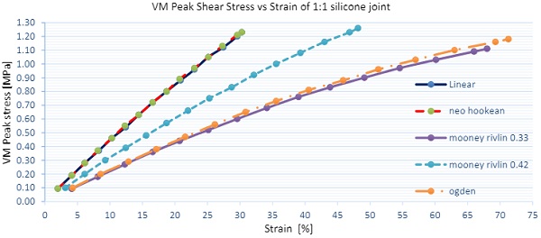
Results for shear load are presented on the figure 16and graph 2. In regards of stress, good correlation between different models is found in main body stress with small variation in peak stress. A tendency of decreased stress for increased aspect ratio was observed. In terms of stiffness of the joint significant variation of 100% were found in between models. Linear elastic material is stiffest with strains of 40%, while Mooney Rivlin and Ogden models are softest with strains of almost 80%. In regards to the aspect ratio similar trend was observed where stiffness increases with larger aspect ratio.
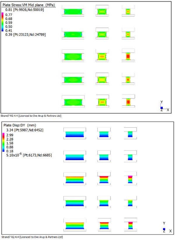
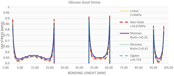
Results for tension load are presented onfigure 17 and graph 2. Very small variation between different models is found in main body stress as well as in the peak stress. A tendency of decreasing stress for increasing aspect ratio was not observed. Stiffness of the joint revealed significant variation of 100% in between models. Linear elastic material model is stiffest correlating to the results as predicted by first principles, while Mooney Rivlin and Ogden model are softest by factor of 3. In regards to the aspect ratio similar trend as in shear loaded elements were observed where stiffness increases with the larger aspect ratio especially for hyper elastic models.
5.Conclusions
Structurally glazed systems behavior against gravity loading is different than the behaviorof capped systems hence, load distribution assumptions for capped systems are not valid for SSG systems. Durability and service ability of the façade system analyzed (hung & sworded) relies upon the long-term performance of the structural silicone hence, designers must verify adequacy of structural silicone against permanent loading on structurally glazed systems.
As justified in the calculations above, the DL distribution within the unit will depend upon: fabrication sequence, the relative stiffness between the glass shoes and the structural silicone and the support state (supported evenly from two brackets (stage1) or held off one bracket and restrained in plane by one of the swords (stage 2)). Design of façade components (glass shoes, brackets, transom-mullion connections) must consider the complexity of structurally glazed systems.
The real behavior of structurally glazed systems must be usedto accurately estimate the actions onto those components and these actions must be used to evaluate their structural adequacy. There are multiple material models available in the literature that are currently used in the engineering practice, all these models correlate in stresses and stiffness for low strain levels (i.e. if the structural silicone design is based onstrain levels below 12.5%).
In light of the results, for higher strain levels the material models analyzed correlate in stresses but significant variation in stiffness is observed.It isexpected that for higher levels of strains, hyper-elastic materials represent the material behaviour more accurately. If elastic models are to be used under high levels of strains, project specific experimental testing should be undertaken in order to determine precisely the spring stiffness of the material under the required level of strain. Aspect ratio dependency was observed in joints with higher aspect ratios.
6. References
[1] Dow Corning® 993. www.dowcorning.com. Accessed 1 Apr 2017
[2] Descamps, P.,·Hayez, V.,·Chabih, M.:Next generation calculation method for structural silicone joint dimensioning, Glass Struct. Eng. (2017).2:169–182, DOI 10.1007/s40940-017-0044-7
[3] Dias, V., Dias, Odenbreit, C., Hechler, O., Scholzen, F., Zineb, T.B.:Development of a constitutive hyperelastic material law for numerical simulations of adhesive steel-glass connections using structural silicone, Int.J.Adhes.Adhes.48, pp. 194-209(2014)
[4] ETAG 002., Guideline for European Technical Approval for Structural Sealant Glazing Kits, European Organisation for Technical Approvals(2012)
[5] Kimberlain, J.:Durability of Structural Silicone Sealant in Cold Bent Glazing Design, Proceeding of GPD, Finland (2019)
[6] Staudt,Y., Schneider,J., Odenbreit,C.:Investigation of the material behaviour of bonded connection with silicone, In: Schneider J, Weller B. (Eds.), Engineered Transparency international conference at glasstec, Düsseldorf, Germany(2014)
[7] Staudta, Y., Odenbreit, C., Schneider,J.:Failure behaviour of silicone adhesive in bonded connections with simple geometry, Int.J.Adhes. Adhes.Volume 82, Pages 126-138(2018)