First presented at GPD 2017
Risks with this approach include higher thermal stresses, especially when low-emissivity coatings are used, and increased chance of spontaneous breakage by nickel sulfide inclusions if fully tempered glass is used to control thermal stress. The thermal stress control benefit of heat treated glass is reduced if a ceramic enamel frit opacifier -which induces a known strength reduction of up to 40%- is applied. Incidences of thermal stress related fracture have occurred with heat strengthened, ceramic enamel frit opacified spandrel glass.
Silicone coatings have been examined as a solution to prevent strength reduction in heat-treated glass when applied as a spandrel opacifier. Four-point bending tests were used to investigate the flexural strength of coated heat strengthened and fully tempered glass. Ball drop testing was used to investigate the impact resistance of coated fully tempered glass. Silicone coatings have no adverse effect on the flexural strength or impact resistance of the substrate and, in some instances, improve it.
These coatings also provide fallout protection in accordance with ASTM C1048 (ASTM, 2012). This suggests using a silicone opacifier on heat-treated spandrel glass could greatly reduce the risk of fracture resulting from thermally induced tensile stress, flexural stress, and impact related glass breakage and reduce the risk of injury from fallout if breakage occurs.
Introduction
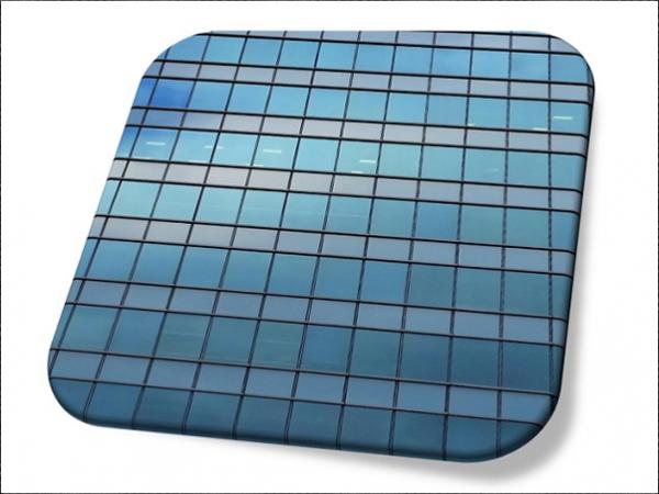
Insulating glass (IG) units have been used in commercial and residential high-rise construction for many years to increase HVAC energy efficiency, and more recently, in the case of spandrel areas, to provide greater color and visual harmonization between vision and spandrel areas. Before the widespread use of IG units, the spandrel areas of a building were mostly monolithic glass applications. In the world of façade glass, there are two types of glass: vision, and spandrel.
Vision glass is transparent to provide viewing areas for occupants and daylight for the interior. Spandrel glass areas, where slab ends, vents, and mechanical parts reside, are opaque. As vision glass improved –greater light transmission and lower reflectance while increasing energy performance– it has become more difficult to visually harmonize the spandrel and vision areas.
This difficulty has been intensified with the increasing prevalence of IG units over monolithic applications for spandrel areas as both tinted glass and colored spandrel coatings work together in combination for improved visual harmony between the areas.
Since the 1990’s, the amount of spandrel glass on a building has fluctuated between 15-30% of a building’s total glass area, as dictated by design trends. Still a sizable area of the building sides, spandrel glass not only contributes to the visual aspects of a building but its energy use as well since IG units improve the energy performance of the spandrel area. Recent energy codes, where the baseline building are governed by lower glazing ratios, are resulting in increased spandrel areas.
However, there are several risks associated with using IG units in a closed spandrel area. One of the most important, commonly known to the industry, is that thermal stresses will increase, particularly in the opacified inboard lite. This is primarily due to heat gain that accumulates in an IG unit as the sun’s rays strike it. The increased heat differential between glass center and edges, often exacerbated by the use of low-emissivity coatings or by dark colors in a spandrel cavity (Mognato and Barbieri, 2013), leads to thermal stresses which can result in fracture.
The accepted rule is that 0.34 MPa (50 psi) hoop stress is created around the edge of a lite of glass for every 0.56°C (1°F°) increase in temperature of the exposed area. Therefore, a center-to-edge temperature difference (∆T) of 56°C (100°F) will create 34.5 MPa (5,000 psi) thermal stress.
Thermal stress issues are further aggravated from the use of ceramic enamel frit as a spandrel opacifier. In recent years, there has been increased awareness in the industry that ceramic enamel frit, used as a spandrel coating, lowers the flexural strength of both heat strengthened (HS) and fully tempered (FT) glass. The degree depends on glass coverage, the colors used, and even the formulation of the ceramic enamel frit itself (Maniatis and Elstner, 2016).
There are several newly published works that discuss the weakness of various heat-treated (HT) products with an applied ceramic enamel frit opacifier; “full coverage black ceramic enamel…reduced the load resistance (LR) of FT glass and HS glass by approximately factors of 2.0” (Natividad et al., in press) and 37.5% reduction of strength (Krampe, 2014).
In summary: laboratory tests have shown significant flexural strength reductions in both new and artificially weathered glass, in both HS and FT glass, when fully covered with a ceramic enamel frit opacifier. Strength reductions, of approximately 50% to 20% have been measured in mean strength and in the 8 per 1000 probability of breakage strength, respectively. Bergers, et al. (2016) attributed the difference between mean strength values and design strength values to the fact that samples with ceramic enamel frit opacifiers have a much lower coefficient of variation, (CoV) than clear samples.
European product standards EN 12150-1 (2015) & EN 1863-2 (2004) address reductions in flexural strength of HT glasses resulting from the application of ceramic enamel frit.
These standards reduce the minimum surface flexural strengths of HT glass from 120 N/mm2 (17400 psi) to 75 N/mm2 (10900 psi) and from 70 N/mm2 (10200 psi) to 45 N/mm2 (6500 psi) for FT and HS glass with ceramic enamel frit, respectively.
The American standard, ASTM E 1300 “Load Resistance of Glass in Buildings” (ASTM, 2016), uses conservative 2X and 4X multiplying factors for the strength of HS and FT glass, when compared to annealed glass. As no field-breakage has been reported from flexural stress in enameled HT glass, there has been little immediate incentive to change the published uniform load strength values in ASTM E 1300-16 (2016).
However, there have been a significant number of thermal stress breakages in IG spandrel units with ceramic enamel frit (Barry and Norville, 2015). In all the reported cases the fracture origin is typically been located 13 mm (0.5”) to 25 mm (1”) in from the cut edge of the glass. Significantly, the fracture origin has always occurred on the glass surface in contact with the ceramic enamel frit and never on the uncoated glass surface. This clearly indicates a relatively large reduction of the tensile strength of HT, in-service, glass with an application of ceramic enamel frit.
In response to the thermal stress failures in the field, FT glass lites have been used in spandrel areas to mitigate thermally induced breakage. However, this increases the risk of spontaneous breakage from nickel sulfide inclusions in FT glass, unless the glass is heat soaked, with a consequent cost increase. Also, if inner lite breakage occurs and goes unnoticed, the LR of the IG unit decreases to where additional fracture may occur allowing glass shards to fall from the spandrel cavity.
As such, there is an increasing need for a spandrel opacifier that does not weaken the glass, but ideally, increases its strength and offers fallout protection. Silicone coatings were examined as a solution to the strength reduction issue created by applying ceramic enamel frit to HT glass as a spandrel opacifier. Investigations were performed using four-point bending and ball drop test methods.
Experimental
1 Four-Point Bending
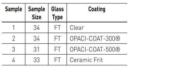
Six samples of HS and six samples of FT 102 x 305 x 6 mm (4 x 12 x ¼ in.) flat glass beams were obtained, with each sample comprised of at least 30 specimens.
Specimens were coated using OPACICOAT-300® a water borne silicone elastomer, or with OPACI-COAT-500® a 100% solids silicone elastomer. All coatings were applied to the air side of the specimen. A total of 193 specimens were tested. All coatings were black. OPACI-COAT-300® was applied via spray gun to 330 µm (13 mils) wet film thickness (WFT).
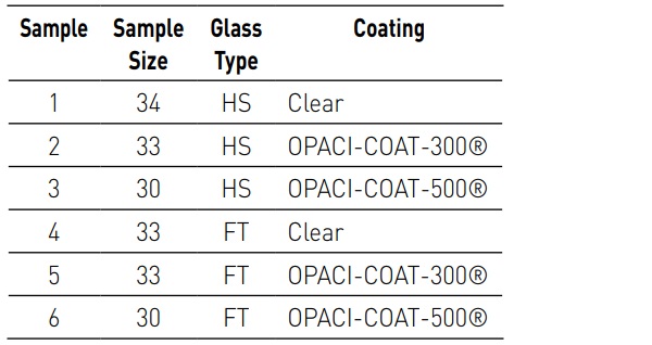
OPACI-COAT-500® was applied via roll coat to 150 µm (6 mils) WFT. Specimens were tested in four-point bending using an MTS machine to provide load at a uniformly increasing rate as per ASTM C 1161-13 (ASTM, 2013). The MTS machine was certified by the American Association for Laboratory Accreditation (ASLA Cert. No. 11455.01) for the basis of the ISO/IEC 17025 international standards for calibration laboratories.
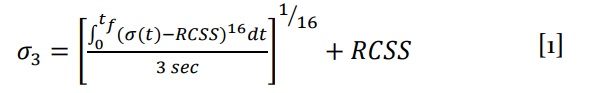
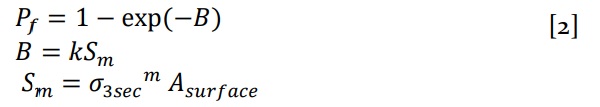
During loading, a data acquisition (DAQ) system captured the load-time history from inception of loading to fracture for each specimen. Each specimen’s load-time history was converted to an equivalent fracture load of three seconds (P3) using traditional beam theory to compute equivalent failure stresses (σ) coupled with the failure prediction model (Beason, 1980) using equation 1:
Where,
σ3 denotes the 3-second equivalent fracture stress
tf denotes time of fracture
σ(t) denotes stress at time, t
RCSS denotes the minimum observed residual compressive surface stress in a sample
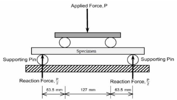
All specimens were installed in the four-point testing mechanism with the float glass air side (coated side) facing down. This orientation induces tensile stresses in the float glass air side and compressive stresses in the float glass tin side during testing. Figure 1 displays a schematic diagram of the testing apparatus. The loading supports spanned 254 mm (10 in.) where each glass beam specimen was placed center to center (c-c) allowing 63.5 mm (2.5 in.) between each support and loading point. The four-point bending creates uniform stresses between the inside loading supports’ 127mm (5 in.) span.
Once installed each test consisted of loading a beam specimen at a rate of 2.54 mm per min (0.1 inches per min), an equivalent loading rate of 445 N per min (100 lbs per min), while the DAQ system recorded the load and time histories at a sampling rate of 10 Hz. Each test concluded with the fracture of the beam specimen, followed by inspection and measurement.
Using the Maximum Likelihood Estimation (MLE), the σ3 values were used to fit a three parameter Weibull distribution to obtain cumulative distribution functions (CDFs) for the P3 using equation 2:
Where,
m, k denote statistical parameters
Asurface denotes the surface area
The CDF’s allow direct comparison concerning LR of clear and coated beam specimens of the same glass type. In this work, LR for the glass beams is defined as the constant applied force with 3-second duration that leads to a probability of breakage equal to or less than 8 per 1000. Work by others (Bergers, et al., 2016) has indicated a reasonable correspondence between results from four-point bending tests and full scale test of rectangular lites.
2 Ball Drop
Four samples of FT 305 x 305 x 3 mm (12 x 12 x 1/8 in.) flat glass beams were obtained, with each sample comprised of at least 30 specimens.
Specimens were coated using OPACICOAT-300® a water-borne silicone elastomer, OPACI-COAT-500® a 100% solids silicone elastomer, or with a ceramic enamel frit. All coatings were applied to the air side of the specimen. A total of 132 specimens were tested. All coatings were black. OPACICOAT-300® was applied via spray gun to 330 µm (13 mils) WFT. OPACI-COAT-500® was applied via rollcoat to 150 µm (6 mils) WFT. Ceramic enamel frit was applied via screen print to 38 µm (1.5 mils) WFT.
Specimens were tested in a ball drop impact test frame following the parameters from a GANA Specification (GANA 76-12-10a, 2008), using a 50 mm (2 in.) diameter steel ball with 535 g mass weighing approximately 5.25 N (1.18 lbs).
Samples were loaded into the test frame, float glass air side (coated side) facing down. Impact height was increased until fracture occurred, at which point drop height was recorded and the specimen inspected.
Results and Discussion
1. Four-Point Bending
All specimen fracture origins lay between the load points on the beam specimens, that is, within the area of constant bending moment and flexural stress. No fracture origin was located on the edge of a specimen.
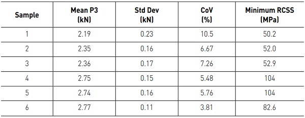
Table 3 summarizes the statistical results for the samples. Researchers used the minimum RCSS for each sample in calculations described.
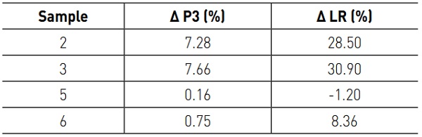
The CoVs for samples of HS glass beams coated with OPACI-COAT-300® and OPACICOAT-500® were relatively small. The small values of CoV led to large and similar values of the statistical parameter m = 17 and m = 18 for Sample 2 and Sample 3, respectively, which were significantly larger than m = 10 for Sample 1. One can make a similar observation concerning values of m and the CoVs for Samples 4, 5, and 6.
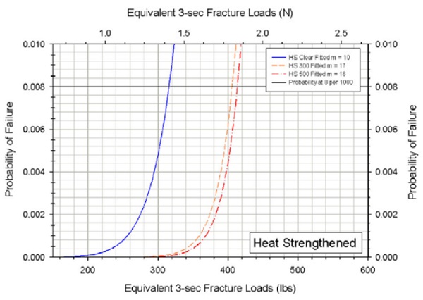
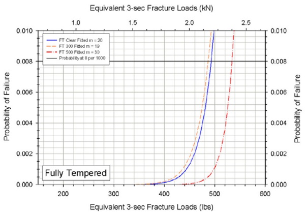
Figures 2 and 3 display the empirical values and CDFs for the P3 values for HS and FT samples respectively while Figures 4 and 5 present the lower portion of the CDFs for HS and FT samples respectively.
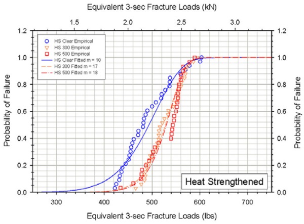
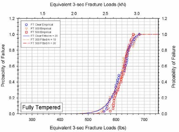
The CDFs in Figures 2 and 4 indicate that both OPACI-COAT-300® and OPACICOAT-500® increased the strength of HS glass a statistically significant amount. This is demonstrated in mean P3 values and most prominently at a probability of breakage less than or equal to 8 per 1000. This data is summarized in Table 4.
In Table 4, Samples 2 and 3 are HS specimens coated with OPACI-COAT-300®, and OPACICOAT-500® respectively, while samples 5 and 6 are FT specimens coated with OPACI-COAT-300®, and OPACI-COAT-500® respectively.
Fully tempered specimens coated with OPACI-COAT® however do not demonstrate a statistically significant change in either P3 or load resistance relative to uncoated specimens.
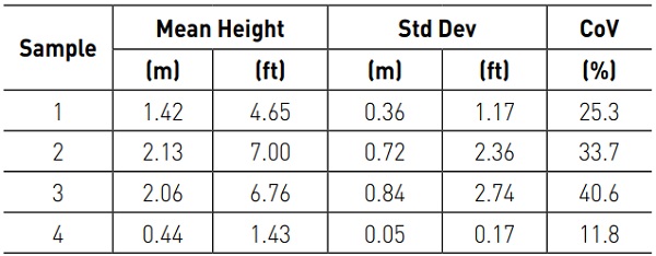
2. Ball Drop
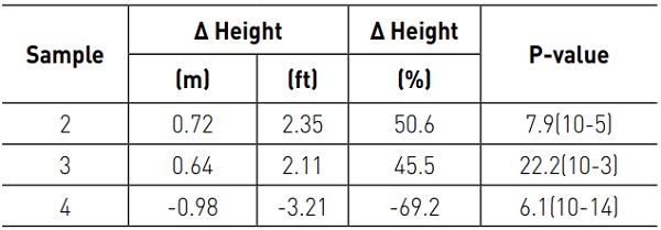
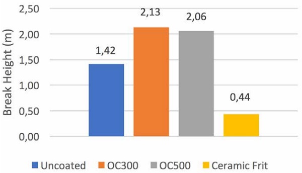
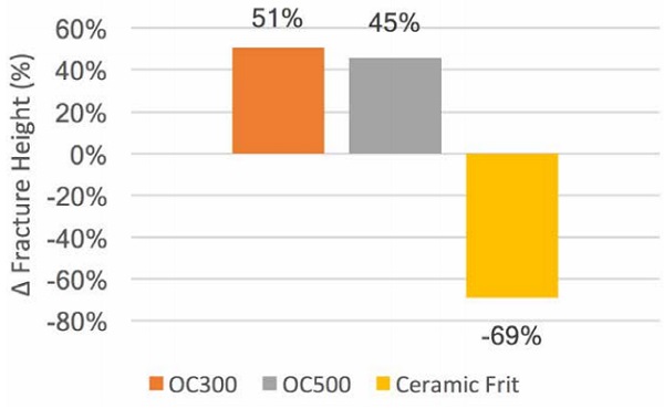
Table 5 summarizes the statistical results for the samples while Figure 6 displays the mean fracture height of all samples. Table 6 shows the statistical values associated with mean fracture heights relative to those of uncoated Sample 1. Figure 7 displays the percent change in fracture height of the sample means relative to that of uncoated Sample 1.
Specimens coated with OPACI-COAT-300® demonstrated a mean increase in fracture height of 0.72 m (2.35 ft.) while specimens coated with OPACI-COAT-500® displayed a mean increase in fracture height of 0.64 m (2.11 ft.). This corresponds to increases of 50.6% and 45.5% respectively. Specimens coated with ceramic frit demonstrated a reduction in break height of 0.98 m (3.2 ft.), or 69.2%.
Conclusions
Four-point bending test results indicate OPACI-COAT® coatings have a positive impact on the flexural strength of HS glass, and have little to no impact on the strength of FT glass. However, ball drop tests displayed a large increase in impact resistance for OPACICOAT® coated FT glass. Since four-point bending is generally considered a more precise flexural strength testing methodology those results should be given greater weight.
It is clear silicone opacifiers, such as OPACICOAT® coatings, certainly do not decrease the LR of HT glass, unlike ceramic enamel frit. As such, silicone opacifiers should be considered instead of ceramic enamel frit as a spandrel opacifier when glass breakage from thermal or bending induced tensile stresses, or from impact loads, is a concern.
References
ASTM (2012): “Standard specification for heat strengthened and fully tempered flat glass” ASTM C 1048-12e1, West Conshohocken, PA.
ASTM (2013): “Standard test method for flexural strengths of advanced ceramics at ambient temperature.” ASTM C 1161-13, West Conshohocken, PA.
ASTM (2016): “Standard practice for determining the load resistance of glass in buildings.” ASTM E 1300- 16, West Conshohocken, PA.
Barry, C., Norville, H.S., (2015): Unexpected Breakage in Ceramic Enameled (Frit) HS IG Spandrels. IGMA Winter Conference, FL, Feb 5.
Beason, W.L., (1980): “A Failure Prediction Model for Window Glass,” Institute for Disaster Research, Texas Tech University, Lubbock (NTIS Accession No. PB81-148421), May.
Bergers, M., Natividad, K., Morse, S., Norville, H.S., (2016); Full Scale Tests of Heat Strengthened Glass with Ceramic Frit. In Glass Structures & Engineering; Springer: Switzerland, Vol. 1, Issue 1, p. 261.
EN 1863-2 (2004): “Glass in building – Heat strengthened soda lime silicate glass – Part 2: Evaluation of conformity/Product Standard” BSI, Brussels.
EN 12150-1 (2015): “Glass in building – Thermally toughened soda lime silicate safety glass” BSI, Brussels.
GANA 76-12-10a (2008): “Fully Tempered Glass Uses Requiring Strength and Resistance to Temperature – Rev #1” Topeka, KS.
Krampe, P. (2014); The strength of enamelled glass. In Challenging Glass 4 & COST Action TU0905 Final Conference; Louter, C., Ed.; Taylor & Francis: London, p. 691.
Maniatis, I., and Elstner, M. (2016); Investigation on the mechanical strength of enamelled glass. In Glass Structures & Engineering; Springer: Switzerland, Vol. 1, Issue 1, p. 277.
Mognato, E., and Barbieri, A. (2013); The breakage of glass – Thermal shock and nickel sulfide inclusion. In COST Action TU0905, Mid-term Conference on Structural Glass; Mocibob, D. Louter, C., Ed.; CRC Press: Boca Raton, p. 155.
Natividad, K., Morse, S.M., and Norville, H.S. (In Press). “Tests of heat treated glass with full coverage ceramic frit.” J. of Architectural Engineering, ASCE.