
First presented at GPD 2019
During the last years, such a global trend has challenged the design and engineering of glass units, frame elements as well as bonding joints in Structural Sealant Glazing (SSG) applications and has pushed for the investigation of material performance and calculation concepts, beyond available standards and guidelines.
With reference to SSG joints, investigation has focused on proposing simplified equations to evaluate cold bending stress and studying relaxation and creeping behavior of silicone adhesives to exploit material performance beyond standard limits. Such investigation process allows identifying where opportunities for systems optimizations are and clarifies that effective cold-bending solutions cannot be uncoupled from new principles of system design, pre-manufacturing and installation.
The development of Mistral Tower in Izmir offers the chance to evaluate in detail the impact of different frame solutions in combination with different production and installation methods and is used to present to system designers and façade producers valuable options and guidelines for approaching design of SSG cold-bent units effectively.
1 Mistral Office Tower Mistral
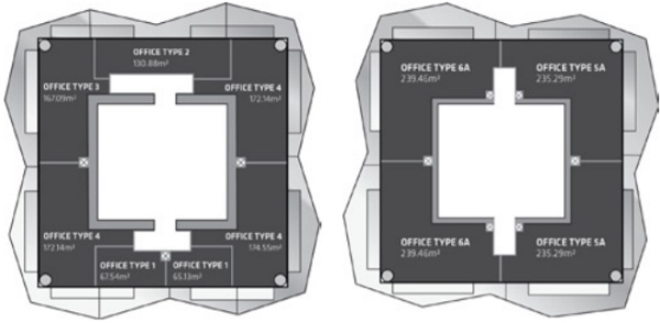
Izmir is a prestigious project in Izmir (Turkey) designed in 2011 by Progetto CMR – Massimo Roj Architects and consisting of a Residential Tower and an Office Tower connected by a Shopping Center (Fig. 1), which are landmarks of the city skyline thanks to their architectural shape and height. This paper focuses on the design of the cold-bent glass façade of the Office Tower, a 46-floor 180m-high building closed by a double skin façade.

The variable layout of the building slabs rotating at each floor level (Fig. 2 and Fig. 3) posed immediately the challenge for the design of a cost-effective solution for the outer glass skin. Advanced parameterization analysis for façade optimization allowed identifying in a cold-bending solution the optimum way to proceed: by use of slight curvatures, a single rectangular façade element to cold-bend up to the required level could be designed to develop the entire building façade.
As in the majority of international projects where complex geometry and sophisticated layouts want to be emphasized by flawless surfaces and transparency, fixing of coldformed glass panels by Structural Sealant Glazing (SSG) systems was the target – with the structural silicone adhesives having the function of ensuring a durable load-bearing connection between frame and glass units.
2 System Details and Boundary Conditions
Typical elements of the outer skin facade consist of a rectangular insulating glazed unit 1528 mm x 4000 mm (width x height), composed by two laminated glass panes 8 mm thick (outer side) and a monolithic glass pane 8 mm thick (inner side) spaced by a cavity 16 mm deep. In order to maximize transparency, solution with IG units bonded by Sikasil® SG-500 structural silicone to aluminium profiles along all four sides was designed.
Following boundary conditions apply for the system design:
– The dead load of all glass panes is permanently supported mechanically;
– The façade components are required to withstand a typical wind load of 2.50 kPa, reaching maximum values up to 4.0 kPa in local areas of the Tower;
– Maximum temperatures expected for glass panels and aluminium frames during service life are 80 °C and 55 °C respectively, according to [1].
– A maximum out-of-plane displacement of +32 mm or -32 mm needs to be imposed at one of the top corners of each façade element by cold-bending.
FE analysis allows to evaluate the magnitude of the loads to apply at the top corner of the elements to cold-bend them up to the required level (Fig. 4). The analysis takes into consideration the effective IGU geometry, glass composition, properties of glass interlayers and stiffness of the IG edge sealing system.
Ftot = 310 N Force to cold-bend the IG unit (short-term analysis)
Ftot = 120 N Force to cold-bend the IG unit (long-term analysis)
Fout = 220 N Force to cold-bend the outer glass pane (short-term analysis)
Fout = 60 N Force to cold-bend the outer glass pane (long-term analysis)
3 Initial Design
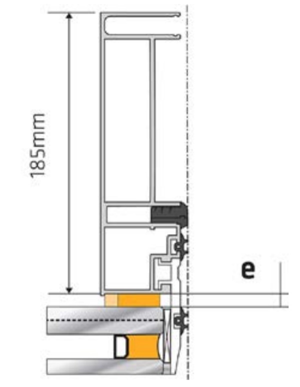
The initial design of the façade elements included flat aluminium profiles 185 mm deep bonded to flat glass units (Fig. 5). The idea was to assemble and install each element as follows:
– The flat IG unit is properly positioned on spacer tapes applied on the flat aluminium frame;
– The gap between frame and glass is filled in by Sikasil® SG-500 silicone;
– When the joints are fully cured, the bonded assembly is moved to site;
– On site, an out-of-plane displacement of 32 mm is imposed by cold-bending at one of the corner of the bonded assembly, to shape and install it.
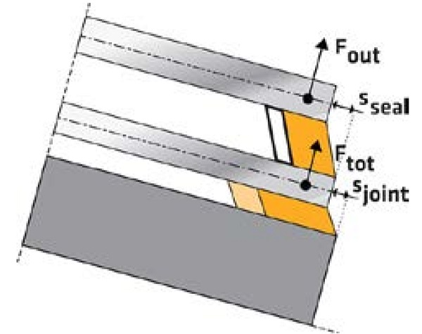
– Described cold-bending procedure introduces into the SG joints [2]:
– Permanent tensile forces Ftot (Fig. 4) caused by restoring of back-flipping forces of displacements elastically imposed to flat units;
– Permanent shear movements sjoint (Fig. 4) due to differential displacements between bonded surfaces, imposed by rotations due to cold-bending.
Based on the initial system designed, Equation 1 allows to calculate [2] that a shear differential displacement sjoint = 3.2 mm needs to be accommodated by the SG joints due to cold-bending.
Based on such displacement, Equation 3 allows to calculate that a minimum thickness of 51 mm would be required for the SG joint.
The value is obtained considering that shear performance of Sikasil® SG-500 are exploited above typical limits set by standards [1] up to a strength value of τ∞,Relax = 0.0315 MPa, which takes into account for adhesive relaxation phenomena under permanent and limited deformation [2].
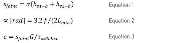
Sjoint = differential displacement between glass and frame
α [rad] = rotation of bonded components
hs1-b = distance of barycenter of bonded section 1 (frame) to bonded area
hs2-b = distance of barycenter of bonded section 2 (glass) to bonded area
f = maximum displacement imposed at corner by cold-bending
Lmin = length of the shortest side of the rectangular unit
e = thickness of the SG joint
G = adhesive shear modulus
τ∞,Relax = adhesive shear strength for permanent displacement imposed
It is immediately clear that required SG joint thickness is unreasonable and opportunities for joint optimization need to be found.
4 SSG Joint Optimization by Frame Design
Equation 1 clarifies that the distance between barycentre of the bonded cross sections (defining the position of bending axis) plays a major role in defining the magnitude of the differential displacement sjoint to be accommodated by the joints; with regard to this, the cross sectional depth of the aluminium profile has for sure the higher influence.
Thus, reducing the depth of the bonded profile offers immediately the opportunity to reduce significantly the minimum SG joint thickness.
Based on such considerations a second façade system was developed and evaluated, including IG units bonded to slim aluminium adapter profiles 6 mm deep. Compared to assembly method of Section 3 (Fig. 5), the idea was to assemble and install each element as follows:
˗ On factory, the flat IG unit is preliminary bonded to the slim aluminum frame by structural silicone Sikasil® SG-500;
˗ When the joints are fully cured, the bonded assemblyis cold bent up to the required level and mechanically fixed to load-bearing profiles either on factory or on site.
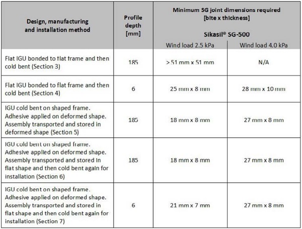
The new design approach allows for a massive joint thickness reduction down to 6 mm by Sikasil® SG-500, due to the cold-bending differential displacement highly reduced to Sjoint = 0.24 mm. Considering all loads involved during system service life (Section 2) and wind loads of 2.50 kPa, a minimum SG joint dimensions of 25 mm x 8 mm (bite x thickness) by Sikasil® SG-500 is required.
It has to be noted that in cold bent systems using a slim profile is valuable if it is ensured that it is free to slide and rotate around its barycentre during the cold bending phase. In other words, it does not make sense to fix mechanically the flat assembly to the main load-bearing frame if it is not cold bent yet. As a consequence, first manufacturing and installation option relied on:
- Bonding the flat slim profile to the flat IG unit on factory and moving the assembly on site when joints are fully cured,
- Cold bending such assembly on site,
- Fix it mechanically to the main loadbearing frame already installed on the main building structure.
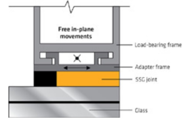
Anyway, if one considers that reducing the bonded profile cross section has only the target to minimize the distance between component bending axis, it is clear that system manufacturing and installation can be simplified by designing a mechanical connection between main profile and slim profile that can ensure free sliding of the slim profile with regard to the load bearing frame.
As a consequence, the use of a slim adapter frame bonded to the glass unit and free to slide into load-bearing frame (Fig. 6) represents a basic requirement to limit cold bending effects on SG joints, while minimizing production and installation efforts. On factory, the flat slim adapter frame already inserted into the main frame can be bonded to the flat IG unit; after joints are completely cured, the assembly can be moved and cold-bent on site for installation.
5 SSG Joint Optimization by Manufacturing Method
Additional options for actively influencing the magnitude of shear movements sjoint in the SG joints exist also by implementing different cold-bending procedures.
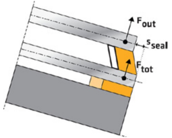
A very effective way to null completely the permanent shear stress in the SG joint due to cold bending is using hot-bent frame members, so that only the flat IG unit needs to be cold bent. Independently from the crosssectional depth of the frame profile, the glass unit can be cold-bent on the pre-shaped frame and temporarily fix to it by mechanical devices; application of the SG joint can follow.
After the adhesive has completely cured, mechanical devices can be removed. As result, tensile forces will stress the joints but introduction of permanent shear stress due to cold bending will be prevented permanently (Fig. 7). Based on façade configuration and loads involved during service life (Section 2), such manufacturing procedure allows reducing SG joint dimensions of Sikasil® SG-500 to 18 mm x 8 mm, considering a maximum wind load of 2.50 kPa.
6 SSG Joint Optimization by Installation Method
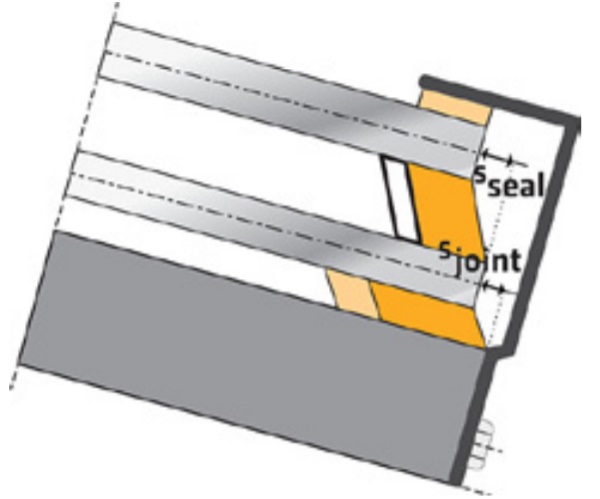
A valuable option to limit the permanent shear stress in the SG joints due to cold bending is to temporary fix the cold bent IG unit by mechanical devices to a cold bent frame; after that, application of the adhesive can follow. When adhesive is fully cured mechanical devices can be removed.
At this stage, shear stress due to elastic back flipping displacements between bonded parts will cause shear stress into the SG joint. Anyway, such assembly will have to be transported to site and there cold-bent again for installation. That means that duration of cold-bending shear stress will be limited only to the timeframe from production (removal of temporary fixing between deformed IG unit and frame) to installation.
It is immediately clear that criteria for controlling such timeframe exist in order to minimize cold-bending effects on SG joints:
– The shorter the timeframe, the shorter the shear stress duration and the lower the impact on SG joint dimensions (the higher the adhesive shear strength offered)
– The lower the temperatures arising on frame and glass during such timeframe, the lower the simultaneous differential displacements occurring between bonded parts due to thermal dilatations.
In Mistral Tower system, implementing the described installation and cold-bending procedure could allow reducing the SG joints dimensions to minimum 18 mm x 8 mm by use of frame 185 mm deep; this considering a maximum temperature of 50 °C for frame and glass and ensuring elements stored in horizontal position in the timeframe from removal of temporary fixings to installation. Such timeframe had to be limited to maximum 7 days.
7 SSG Joint Optimization by Combined Methods
Cold-bending procedure described in Section 6 combined with frame design consideration provided in Section 4 gives the chance to reduce further the SSG joint dimensions. As temporary shear displacements are introduced into the joints due to cold bending, it is obvious that cross sectional depth of the bonded profile has an impact on SG joint dimensions. Of course, the shorter the displacement duration, the lower the impact of cross sectional depth on joints.
Considering same conditions and cold-bending procedure mentioned in Section 6 but including a slideable adapter frame 6 mm thick, SG joint by Sikasil® SG-500 could be applied according to a minimum dimensions of 21 mm x 7 mm, which minimizes joint thickness.
Opportunities for reducing SG joint bite also exist. A typical strategy is using permanent mechanical devices to restrain the glass unit to the frame (Fig. 8), so that no permanent tensile forces due to cold bending are transferred to the joints. Anyway, using such devices was excluded in Mistral Tower due to the aesthetical impact on the final facade.
System described in Section 6 was finally selected for design and construction of the outer skin façade. Such a method that required strong limitations in transportation time was possible due to the lucky situation where the location of the production factory was very close to the installation site.
8 Evaluating the influence of the frame cross-sectional depth by FEM analysis
To estimate the influence of the frame height on stresses introduced into SG joints, a numerical analysis was performed with the multiphysics finite element code ANSYS (version 18.2). All parts of the façade system (aluminium profiles, glass, interlayer, SG and IG joint) were idealized using volume elements. To estimate the stresses in an appropriate way, isotropic hyperelastic material model for the Sikasil® SG-500 structural silicones was used, as this resembles the stress-strain behaviour in good approximation [3] [4]. The material parameters are given in [5] The following assumptions were made for the numerical calculation:
– Volume elements Solid 186 for all components: SOLID186 is a higher order 3-D 20-node solid element that exhibits quadratic displacement behaviour
– Rectangular cross-section with equivalent bending stiffness to the actual substructure for the aluminium profiles
– Brick volume elements with an aspect ratio close to 1 and a meshing size of 4 mm for the relevant SG joints
– Polynomial (n = 2) hyperelastic model for the SG joints according to [5]
– Linear elastic material behaviour for aluminium, IG joint, glass and PVB interlayer
– Bonded contact between SG joint and glass, between SG joint and aluminium profile and between IG joint and glass – Local nodal support at the corners of the supporting frame.
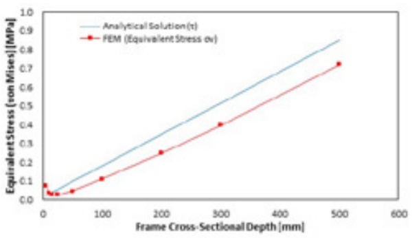
In order to estimate the influence of the frame cross-sectional depth on the stress introduced into the SG joints due to cold-bending, the profile depth was varied in the finite element calculation. Results are plotted in Fig. 9 and compared to the analytical solution of Equation 1. A linear relationship between the profile height and the resulting stress is confirmed.
The initial stress increase obtained by FEM analysis for very low profile depths results from the decrease in bending stiffness, which was not adjusted for this calculation. The results of the numerical simulation are qualitatively and quantitatively consistent with the analytical solution. The analytical solution, however, slightly overestimates the stress and is therefore on the safe side for the dimensioning.
9 Conclusions
The development of Mistral Tower in Izmir offers the chance to evaluate in detail the impact of different frame solutions in combinations with different production and installation methods on SSG joints of cold-bent façade elements.
The design of slim adapter frame free to slide into load-bearing frame represents a basic requirement to limit cold bending effects while minimizing production efforts. Valuable SG joint optimization results can be further achieved if bonding on either pre-shaped (hotbent) frame or pre-shaped (cold-bent) frame/ glass assembly is possible, or if cold-bending stress can be confined to a limited timeframe by a clever production method in controlled conditions.
With reference to the facade system used in Mistral Tower, advanced FEM simulation is implemented to estimate the influence of the cross sectional depth of the bonded profile on the stress in the SG joints. In line with the simplified equations proposed, the analysis confirms that a linear relationship exists between depth of bonded frame and stress on SG joints, proving that the slimmer the bonded frame the smaller the differential displacement imposed to SG joints and the smaller the joint thickness required.
10 References
[1] EOTA ETAG 002-1, Guideline for European Technical Approval for Structural Sealant Glazing Kits (SSGK) – Part 1: Supported and Unsupported Systems (2012).
[2] Nardini, V., Doebbel, F.: Structural Silicone Joints in Cold-Bent SSG Units. GPD Glass Performance Days 2017, Complex Geometry, Tampere. pp 23-27.
[3] Clifta, C. D., Carbaryb, L. D., Hutleya, P., & Kimberlainc, J. Next generation structural silicone glazing. Journal of Facade Design and Engineering, 2014, Vol. 2, pp 137-161.
[4] Staudt, Y. Investigation of the material behavior of glued connections with silicone. Darmstadt: Master Thesis at Technische Universität Darmstadt, 2013.
[5] Sika Technology: Hyperelastic constitutive models for the FE simulation of Sikasil® SG-500. 09.09.2013.
[6] Sika Services AG: Additional Technical Information for computer-aided analysis to simulate the joint behavior in façade applications using Sikasil® SG adhesives. 02.02.2017.