Review of Research Projects and Applications
This article is a reprint from the journal
“Architecture • Civil Engineering • Environment – ACEE”
published by the Silesian University of Technology.
Marcin KOZŁOWSKI
MSc Eng., PhD student; Faculty of Civil Engineering, The Silesian University of Technology, Akademicka 5, 44-100 Gliwice, Poland
E-mail address: marcin.kozlowski@polsl.pl
Abstract:
The article presents an overview of research and applications of glass as structural material, cooperating with other materials: steel, timber, glass or carbon fibre composites. It presents examples of reinforced glass structural elements as well as complex composite components. The most promising seem to be beams with a glass web and flanges made of timber (preferably laminated). In the near future, the author plans to conduct the laboratory research on hybrid timber-glass beams on the full-scale models.
Keywords:
Structural glass, Glass beam, Reinforced glass, Composite glass beam, Hybrid glass structures
1. Introduction
There are many materials that seem to be non-structural but after study their properties thoroughly they present a huge potential to build modern, safe and durable architecture. One of such examples is glass. However, the material glass itself poses many difficulties in structural considerations. The one results from its brittleness. When overloaded glass breaks immediately into shards without warning. Secondly, glass is much weaker in tension than in compression therefore it becomes a problem to fully exploit its strength in bending. Lastly, glass is extremely susceptible to stress concentrations so there is a big challenge to design structural connections between glass and other materials.
A traditional approach to design glass elements takes into account above mentioned issues and involves the use of tempered glass which demonstrates higher strength than annealed float glass, laminating few panes together to minimize the probability of total glass failure, dimensioning with very high safety factors and applying sacrificial sheets to the laminate to protect the load-bearing sheets. The conservative techniques seem to be uneconomical and do not fully use the potential of the material.
In the last decade several research projects focused on glass combined with other materials have been started. The concept of reinforced glass beam was to strengthen a glass beam with a strip made of steel [1-4], carbon fibre [5] and glass fibre [6] bonded to the tensile side of the beam. The idea of hybrid glass beam was to combine a glass web with flanges made of steel [7, 8], concrete [9] and timber [10-13]. These research projects show a tendency to seek ductility and post-breakage safety. The paper presents the results of the studies and applications.
2. Material properties of glass
The most important physical properties of glass are summarized in Table 1.
Table 1
Physical properties of glass [14].
Glass with a density comparable to reinforced concrete presents modulus of elasticity almost equal to that of aluminium. Glass shows isotropic and almost perfectly elastic behaviour. Due to its brittle manner glass does not yield plastically and therefore is very susceptible to stress concentrations. Glass is several times weaker in tension than in compression. The practical strength of glass can be improved in tempering process which is about introduction of a surface compressive residual stress by a heat treatment of glass.
Since the surface tensile stress due to actions is smaller than the residual compressive stress in tempered glass, no crack will develop. The fracture pattern of glass is highly dependent on residual stress. Annealed float glass breaks into large fragments whereas fully tempered glass presents high fragmentation and breaks into small pieces which does not affect post-breakage strength.
3. Review of research projects and applications
3.1 Metal reinforced glass beams
Comparing the load-bearing capacity of different glass beams in four configurations of glass strips: layered (three strip of glass bonded directly), laminated (three strip of glass laminated with a 1 mm polycarbonate interlayer), laminated segmented and laminated reinforced glass, Veer [1] has proved that even small amount of steel bonded to tensile side of a glass beam improves the post-breakage performance of the beam significantly.
A 3000 mm long reinforced glass beam with a stainless steel L-profile 3 x 3 mm of 1 mm thickness bonded to the bottom of the glass beam was examined in a three-point bending test. Looking at the load−displacement curve (Fig. 1) three peaks can be identified. Each peak corresponds to the failure of a single pane. As can be noticed even after first pane breaks, the stress is redistributed and almost the same strength is achieved. It relates to the fact that when first pane fails, the tensile stress is taken by the steel L-profile.
Fig. 1 - By ACEE Journal
Force−displacement curve of a three-point bending test of 3000 mm long metal reinforced glass beam [1].
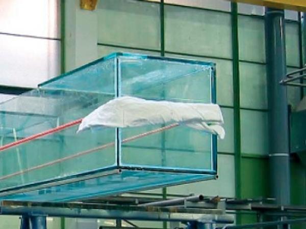
In 2002 under the Studium Generale group of Delft University of Technology, Veer [2] focused on the project of a 8000 mm long aquarium for the atrium in the main library of the university. The designed beam had a cross-section of a 300 x 300 mm box with a few openings in top plates to let the fish breathe.
Because the glass plates were not available in lengths more than 6000 mm it was decided to divide the beam and solve the problem using two 4000 mm long boxes connected by two overlapping side plates. To increase the bearing capacity of the structure and avoid brittle failure of glass two stainless steel tubes of a wall thickness of 1 mm and cross-section of 10 x 10 mm were bonded to the bottom plate (under the vertical glass plates) (Fig. 2).
Fig. 2 - By ACEE Journal
The 4000 mm long prototype with two stainless steel profiles bonded to the bottom plate during lifting process [15].
A preliminary FEM study showed that it was possible to build the aquarium with 10 mm thick plates made of annealed float glass bonded together with adhesive. Two 4000 mm long prototypes were built but only one was examined in a three-point bending test. At a load of 14.5 kN the beam failed rapidly within a second by crack growth in all glass panes (Fig. 3). The promising results of tests on the prototype allowed to start building a full-scale model.
Alike the prototype, the 4000 mm long beam was tested in a three-point bending test and at a load of 16 kN crack started to form in the centre of the beam. In contrast to the rapid failure of the prototype, the beam failed slowly (Fig. 3). A probable reason was that both beams were made of the same glass thickness, thus the 4000 mm long beam was stiffer which caused rapid and explosive failure of the specimen.
The tests confirmed the feasibility of the design but finally due to the uncertainties it was decided to resign on the project of the 8000 mm long aquarium. Instead, the second, not tested 4000 mm long prototype was placed in the library as an aquarium and located one meter above the pavement.
Fig. 3 - By ACEE Journal
Failure mode of the prototype (up) and crack forming in a 8000 mm long beam (down) [2, 15].
The reinforced box-section glass beam concept was developed by Bos [3]. A 3000 mm long prototype of 210 x 70 mm cross-section dimensions was composed of 1500 mm long segmented of 6 mm thick annealed float glass sheets. Two small stainless steel profiles 10 x 10 x 1 mm were bonded to the underside of the side plates.
The beam was examined in a four-point bending test. At the load of 10.8 kN first visible crack appeared but the maximum load just before the failure was 14.3 kN. The prototype showed a post-initial crack strength of almost 135 %.
In 2004 following the research on box-section glass beam, Bos focused on the concept of post-tensioning of glass beams [3]. The parabolic, prestressed T-section had a changing cross-section dimensions, with a height of 210 mm and flange width of 90 mm in the mid-span decreasing to 110 mm and 60 mm for a height and a flange with, respectively, at the ends.
The web consisted of a middle 10 mm thick glass sheet and two 8 mm outer layers. The flange was composed of two 8 mm sheets (Fig. 4). All the glass sheets building the web and the flange were segmented in 750 and 1500 mm long sheets.
Fig. 4 - By ACEE Journal
The prototype T-section beam [3].
Under the middle glass sheet of the web a stainless steel box section 10 x 10 x 1 mm was bonded. The beam was tensioned to 20 kN by a high-strength steel rod with a diameter of 7 mm inserted through the stainless steel hollow profile. Then the prototype was tested in a four-point bending test. The first crack formed at the load of 20.5 kN and at the load of 23.9 kN beam broke explosively. The prototype showed a post-initial crack strength of almost 120 %. The influence of post-tensioning on the buckling resistance of the glass T-beam was also investigated by Belis [16].
A more detailed research on post-tensioned beams and methods of transferring tensioning forces to the beam supported by bending tests on full-scale models can be also found in [17].
In 2004 at Delft University of Technology an All Transparent Pavilion was designed and built (Fig. 5) [4].
Fig. 5 - By ACEE Journal
All Transparent Pavilion exhibited at Delft University of Technology [4].
The main load-bearing element of the roof structure was a glass beam supported by glass columns and secured from lateral buckling by glass purlins placed every 1200 mm. The beam had a span of 4800 mm with two 1200 mm cantilevers at both ends. Between the supports the beam was 385 mm high and outside the supports the height was reduced to 230 mm. The beam was composed of four 15 mm sheets between the columns and two 15 mm sheets at cantilever part.
Due to the significant length of the beam the sheets were divided into segments and bonded together with an adhesive. Because of the cantilevers the bending moment distribution required stainless steel reinforcement on the top and bottom part of the beam. A three-point bending test was performed to investigate the structural behaviour of the beam. The tests showed that the beam was able to withstand a load almost 50 % higher than the load that caused initial failure (Fig. 6).
Fig. 6 - By ACEE Journal
Force−vertical displacement curve of a three-point bending test of a 7200 mm long beam [4].
Results of an experimental research on different reinforcement geometries of steel reinforced glass beams can be also found in [18, 19]. Group of researchers confirms a positive effect of adding a steel profile to the tensile side of a glass web on the load-bearing capacity and post-failure behaviour of the steel reinforced glass beam. Due to different cross-sections and spans of the specimens it is difficult to compare results. The specimens showed the post initial crack strength from 120 to 150 %. Nevertheless, some conclusions can be drawn.
In case of local failure of glass a stress distribution occurs where the steel profile carries the tensile stress and the beam can withstand higher load. The part of load between first crack and total failure is called a safety margin. The structure provides a warning signal that something is wrong and gives time to prevent a total failure. Moreover, the research shows that although the steel reinforced glass beam concept does not solve the problem of torsional buckling failure, it can be solved by proper design of cross section of beam e.g. a T-shaped or a box-section.
3.2 Carbon and glass fibre reinforced glass beams
Probably the first research on carbon fibre reinforced glass beams was performed by Palumbo [5]. A carbon fibre strip was bonded to the bottom edge of a glass beam with a structural adhesive. The main role of the solution was to tie all glass sheets together and strengthen the beam by decreasing the value of tensile stress acting on the glass beam by moving down the neutral axis.
The idea was examined in a three-point bending test on a 1100 mm long laminated beam consisting of four sheets made of float glass. It was concluded that carbon fibre reinforcement significantly increases the load bearing capacity of the beam and in case of glass failure the carbon fibre strip will hold the shards together and the beam will not collapse. The concept was applied in the restoration of the saddle roof of XIII century “Loggia de Vicari” located in northern Italy (Fig. 7).
Fig. 7 - By ACEE Journal
6000 mm long glass beams with carbon fibre reinforcement as load-bearing elements of the saddle roof structure of “Loggia de Vicari” [5].
Glass fibre reinforced glass beams were researched by Louter [6]. The main idea was to embed glass fibre rods in the interlayer of a laminated glass beam. To place the rods at intended positions the polymer interlayer material SentryGlass was applied. The Sentry Glass provides good shear stiffness, high bond strength and it easily adapts to the geometry of the glass fibre reinforcement rods during lamination process. To investigate the bond strength of the rods to the laminate a series of pull-out tests were conducted.
Two specimen types were examined: round rods with a diameter of 2 mm and flat rods with section dimensions of 0.8 x 6 mm at -20, 23 and 60ºC. The tests showed that at all temperatures the pull-out strength of the specimens with flat rods was higher than the pull-out strength of the specimens with round rods. It can be explained by a larger bond area of the flat specimens compared to the round specimens.
To investigate the influence of glass fibre rods embedded in the interlayer of a glass laminate on the post-breakage behaviour of the beam, a series of tests were performed. The beam samples with a length of 1500 mm were composed of a double-layer glass laminate with either 5 round or 3 flat glass fibre reinforcement rods (Fig. 8). The tests showed that the beams with flat reinforcement rods showed higher post-breakage strength and stiffness than the beams with round reinforcement rods.
Fig. 8 - By ACEE Journal
Exploded cross-section of the beam specimens with round and flat rods: 5 round (left) or 3 flat (right) glass fibre reinforcement rods [6].
Undeniable features of carbon and glass fibres are high strength and stiffness. These allow to design glass beams with high post-breakage strength using minimum material. A fibre strip bonded to the tensile side of a glass beam significantly improves redundancy and post-breakage behaviour of carbon and glass fibre reinforced glass beams. However, the concept demands complicated manufacturing process and expensive materials.
3.3 Hybrid steel−glass beams
Hybrid steel−glass beams were researched by Wellershoff [7] at Institute of Steel Construction at RWTH Aachen. The cross-section of the beam consisted of a glass web adhesively bonded to steel angles screwed to steel rectangular flanges (Fig. 9). The prefabricated 3600 mm long I-shaped hybrid beam was build and examined in a four-point bending test.
Fig. 9 - By ACEE Journal
A cross-section of the hybrid steel-glass beam [7].
At a load of 137.8 kN first crack was observed. At the same time the test was stopped due to large deflection of the specimen. The load bearing capacity of the hybrid beam seems to be impressive if compared with a pure glass beam. The theoretical load that causes buckling failure of a pure glass beam of the same dimensions as the tested beam was estimated at 29.6 kN.
Similar studies of hybrid steel-glass beams were performed by Ungermann [8] at Institute of Steel Construction at Dortmund University. In contrast to Wellershoff’s [7] research the steel flanges were bonded directly (with no transitional angles) to the glass web. 4000 mm long specimens consisted of a web built of two 12 mm toughened glass panes laminated together and steel flanges with a cross-section of 10 x 80 mm. The flanges were bonded to the web with three different adhesives: polyurethane, epoxy resin and silicone.
The beams were examined in a four-point bending test. To avoid the failure caused by lateral buckling of the beam a lateral support was built at mid-span. To interpret the influence of steel flanges application on a load-bearing capacity of the hybrid beams a failure load of a glass fin without flanges was estimated to be 40 kN (based on a glass strength of 120 MPa). The studies proved that stress distribution in the hybrid steel-glass beams was highly dependent on the stiffness of the adhesive connecting the glass web and the steel flanges (Fig. 10).
Fig. 10 - By ACEE Journal
Load carrying capacity of hybrid steel−glass beams with joints made of different adhesives (TS4 – silicone, TS1 – polyurethane, TS3 – epoxy resin) [8].
In case of a silicone adhesive the specimen reached the load of 52.8 kN before first crack occurred. Due to low stiffness of silicone the flanges had small contribution in carrying forces and the beam failed due to glass failure. An increase of 32 % with recpect to the failure load of the glass fin without flanges was explained by the fact that the glass strength was higher than expected.
The beam with polyurethane adhesive (stiffer than silicone) showed the same behaviour at the load of 72.1 kN. An increase of 180 % was explained by the glass strength as well. The highest load-carrying capacity was shown by the beam with joints made of epoxy resin – 126.6 kN. The adhesive was so stiff that the steel flanges played a main role in carrying forces and almost reached the yield strength. In the test an 316 % increase of failure load was achieved.
Studies presented before confirm an increase of load-bearing capacity of glass beams with steel flanges bonded by linear adhesive connections. This concept can be applied particularly in a design of glass fins, girders and columns where the lateral torsional buckling resistance is crucial. The research of Ungermann [8] proves that the stiffness of adhesive has a strong influence on stress distribution in hybrid beams. The greater stiffness of the adhesive the higher contribution of load transmission in flanges and smaller damage intensity of glass.
3.4 Hybrid concrete-glass beams
A research on glass−concrete composite beams was performed by Freytag [9] at Graz University of Technology. Freytag [9] presented structural behaviour and detailed theoretical failure mechanism of a hybrid concrete−glass beam. A 7800 mm long beam consisted of a glass web and two flanges made of ultra-high-performance concrete (Fig. 11).
The web was composed of three 8 mm panes made of fully tempered glass resin laminated together. The direct connection between glass and concrete was made by placing the web into the form before pouring fresh concrete. To ensure proper joint the glass was specially pretreated by roughening the surfaces.
Fig. 11 - By ACEE Journal
The cross-section of the glass-concrete beam and the specimen during test [9].
To validate the concept two experiments were performed. The bottom flange of the first beam was prestressed by unbonded tendons placed in the bottom flange of the beam to close the cracks caused by shrinkage of concrete and retrieve the original stiffness. The second specimen was simply reinforced. The experiments showed a strong influence of prestressing on the load-bearing capacity of the glass−concrete composite beams. The prestressed beam failed at a load of 257 kN whereas the second achieved maximum load of 100 kN.
The experiments proved the high load-bearing capacity of glass−concrete beams. However, the concept demands complicated manufacturing process and special treatment of a glass surface before pouring the fresh concrete into formwork. In the project fully toughened glass has been used. In case of a glass failure there is no post-breakage stiffness of a glass web so shear forces will be transferred only via concrete flanges. Furthermore, the alkaline concrete can corrode the glass.
3.5 Hybrid timber−glass beams
Timber−glass composite beams were researched by Hamm [10, 20] at École Polytechnique Fédérale de Lausanne. Eight 4000 mm long and 250 mm high beams with various cross-sections of timber flanges were built and tested. The web of all the specimens was 10 mm thick and made of annealed float glass. The laminated timber flanges were glued to the web by a polyurethane adhesive. The height of the flanges varied from 50 mm to 30 mm and the width was 60 and 50 mm.
At both ends two timber posts were applied to place the beam on the supports. The beams were examined in a four-point bending test. To make sure that the forces are applied directly to the timber flanges instead of the glass web wooden blocks were placed under the jacks. All the specimens showed a similar behaviour. First cracks started to form long before the failure of the beam (Fig. 12). After each crack occurrence a small reduction of stiffness was noticed.
Fig. 12 - By ACEE Journal
Force–displacement curve for the 4000 mm long timber−glass composite beam [10].
Fig. 13 - By ACEE Journal
A beam after failure presenting a typical fracture pattern for timber−glass hybrid beam with the web made of annealed float glass [10].
Comprehensive research on I-shaped timber−glass composite beams including float, heat-strengthened and fully tempered glass were performed by Kreher [11] at École Polytechnique Fédérale de Lausanne. All beams were 150 mm high and spanned 2000 mm with a web thickness of 4 and 6 mm. The cross-section of flanges varied from 20 x 20 mm to 50 x 50 mm. All specimens were tested in a four-point bending test. The tests results proved that edge processing (finishing) had crucial influence on strength of the glass.
The wooden flanges increased the stiffness of the beam and were suitable as a load introduction and support. Moreover, the flanges bonded to the tensile side of the beam acted as reinforcement and when a crack formed they behaved as a crack bridge taking over tensile stress. This allowed a ductile structural behaviour of composite beams and increased residual strength up to 300%. Kreher [11] in his thesis presented also an analytical approach to calculation of stresses and deflection of timber−glass composite beams.
The concept developed by Kreher [11] was tested on a full-scale model and applied in the construction of the Palafitte hotel in Switzerland [21]. The main load-bearing element of the roof structure was a timber−glass composite beam with a span of 6000 mm.
The cross-section was composed of a glass web with wooden members bonded on both sides (Fig. 14). The upper flange was composed of two timber joists 100 x 160 mm and for the lower flange two joists 65 x 65 mm were used. The web was a single glass pane 580 mm high and 12 mm thick made of fully toughened glass. To ensure the structural safety of the beam in case of failure of glass the timber members were designed to resist the full load.
Fig. 14 - By ACEE Journal
Timber−glass composite beams in the conference room in the Palafitte hotel [11].
Timber−glass composite beams as structural elements suitable for glass housing model with more than one storey were developed by Cruz and Pequeno [12]. For the concept 20 beams were tested – 15 composite beams with timber flanges 70 x 100 mm, four timber beams and one glass beam. I-profile and rectangular section of the composite beams were tested, also with and without vertical supports.
The 500 mm high web was a laminate consisting of two 6 mm annealed float glass sheets. Three adhesive types were examined: polymer, silicone and polyurethane. The span of the specimens varied from 650 to 3200 mm. Fig. 15 shows the results of a four-point bending test of the beams.
Whereas the timber beam failed at a load of 15 kN with deflection of 50 mm, the all-glass beam failed at a load of 19 kN with deflection of 5 mm. The results of the composite timber−glass beam bonded with adhesives is a combination of propositions of beams mentioned before. At a load of 35 kN a first crack appeared in the I-section beam, but the failure load was 65 kN. The rectangular-section beam cracked at the load of 50 kN then failed at the load of 67 kN due to adhesive failure. The I-section composite beam showed a significant post initial crack strength of almost 185 %.
Timber−glass composite beams were also researched by Blyberg and Serrano [13] at Linnæus University as a part of research project with official name “Glass and Timber – Innovative Building Components with Added-Value”. All specimens were 3850 mm long and 240 mm high. The glass web 200 x 3850 mm with a thickness of 10 mm was made of annealed float glass. Two types of glass edges were tested: polished and non-treated.
The wooden flanges were 45 x 60 mm with 25 mm high grooves and widths: 13 and 15 mm. To bond the flanges to the glass web three types of adhesives were studied: acrylic, silicone and polycarbonate. The most promising results showed the beam with acrylate adhesive. The 140 % increase of failure load was noted after the first crack was observed.
A Group of researches on timber−glass composite beams presented before shows a huge potential of combination of timber and glass in beam components. This concept provides ductility and prevents brittle failure of a glass beam. In addition, it offers a high post-breakage strength after possible glass failure.
Fig. 15 - By ACEE Journal
Load−vertical displacement curves of 3200 mm long beams: A (timber beam), B (glass beam 6.6.1), C (I-section timber−glass composite beam, silicone adhesive), D (rectangular section timber−glass composite beam, silicone adhesive) [12].
4. Conclusions
The reinforced glass beam and hybrid glass beam concepts offer many demonstrable advantages. The first is redundancy. After glass failure the reinforcement (or non-glass bottom flanges) acts as a crack bridge which together with an uncracked compressive zone of the web (or top flanges) allows the beam to still carry the load. The second is ductility. The concepts allow for much greater deflection than a pure glass beam.
The third is a high post-breakage strength of composite beams after glass failure. There is a considerable safety margin between first crack and total failure of the beam. It provides a warning signal that something is wrong with the beam and gives time to prevent the beam from total collapse. All of these features make the composite glass beam concept a safe load-bearing system.
Among all the materials used in the presented researches timber, besides meeting the above requirements, deserves a special attention. It is a natural, ecological and recyclable material. Its mechanical properties allow to transfer tensile stress. Timber flanges also provide a good lateral restraint of a glass web simultaneously protecting the most sensitive part of the glass plate – the edges.
Moreover, timber is easy to manufacture and appropriate for producing pre-fabricated elements that affect the economical aspect of the building process. The association of mechanical capacity of glass and timber, environmental sustainability and recyclability let believe that timber−glass composites have a huge potential in structural applications.
5. References
[1] Veer F.A., Rijgersberg H., Ruytenbeek D. Et al.; Composite Glass Beams, the Third Chapter. Glass Processing Days, Tampere, Finland, 2003
[2] Veer F.A., Gross S., Hobbelman G.J. et al.; Spanning Structures in Glass. Glass Processing Days, Tampere, Finland, 2003, pp. 78-81
[3] Bos F.P., Veer F.A., Hobbelman G.J. et al.; Stainless steel reinforced and post-tensioned glass beams. ICEM12 - 12th International Conference on Experimental Mechanics, Politecnico di Bari, Italy, 2004
[4] Louter C., Bos F., Veer F.A. et al.; Reinforced Glass Cantilever Beams. Glass Processing Days, Tampere, Finland, 2005
[5] Palumbo M.; A New Roof for the XIIIth Century "Loggia de Vicari" (Arquà Petrarca -PD Italy) Based on Structural Glass Trusses: A Case Study. Glass Processing Days, Tempere, Finland, 2005
[6] Louter C., Bos F., Veer F.A.; Structural Glass Beams with Embedded Glass Fibre Reinforcement. Challenging Glass 2, Conference on Architectural and Structural Applications of Glass, TU Delft, Netherlands, 2010, p. 439-448
[7] Wellershoff F., S. Gerhard S.; Structural Use of Glass in Hybrid Elements: Steel-Glass-Beams, Glass-GFRP-Plates. Glass Processing Days, Tampere, Finland, 2003
[8] Ungermann D., Preckwinkel E.; Structural Behaviour of Hybrid Steel-Glass Beams. Challenging Glass 2, TU Delft, Nederland, 2010
[9] Freytag B.; Glass-Concrete Composite Technology. Structural Engineering International, Vol.14, No.2, 2004; p. 111-117
[10] Hamm J.; Tragverhalten von Holz und Holzwerkstoffen im statischen Verbund mit Glas. Thesis no. 2065, École Polytechnique Fédérale de Lausanne, Lausanne, 2000
[11] Kreher K.; Tragverhalten und Bemessung von Holz-Glas-Verbundträgern unter Berücksichtigung der Eigenspannungen im Glas. Thesis no. 2999, École Polytechnique Fédérale de Lausanne, Lausanne, Switzerland, 2004
[12] Cruz P., J. Pequeno J.; Timber-Glass Composite Beams: Mechanical Behaviour & Architectural Solutions. Challenging Glass Conference 1, Delft University of Technology, Netherlands, 2008
[13] Blyberg L., Serrano E.; Timber/Glass Adhesively Bonded I-beams. Glass Performance Days, Tampere, Finland, 2011
[14] Hess R.; Material Glass. Structural Engineering International Vol.14, No. 2, 2004; p. 76-79
[15] Studium Generale Group Website, http://www.materialenreeks.tudelft.nl/glas.html
[16] Belis J., Louter C., Verfaillie K. et al.; The Effect of Post-Tensioning On the Buckling Behaviour of a Glass T-beam. Proceedings ISAAG 2006 Conference, Munich, 2006
[17] Gdoutos E.E., Louter C., Heusden J. et al.; Post-Tensioned Glass Beams. Fracture of Nano and Engineering Materials and Structures, Springer Netherlands, 2006; p. 597-598
[18] Louter C.; Adhesively bonded reiforced glass beams. Heron, Vol.52, 2007
[19] Weller B., Meier A., Weimar T.; Glass-Steel Beams as Structural Members of Façades. Challenging Glass 2, TU Delft, Nederland, 2010
[20] Hamm J.; Development of Timber-Glass Prefabricated Structural Elements. Innovative Wodden Structures and Bridges, Lahti, Finland, 2001
[21] Kreher K., Natterer J.; Timber-Glass Composite Girders for a Hotel in Switzerland. Structural Engineering International, Vol.14, No.2, 2004