Article Information
- Digital Object Identifier (DOI): 10.47982/cgc.8.438
- This article is part of the Challenging Glass Conference Proceedings, Volume 8, 2022, Belis, Bos & Louter (Eds.)
- Published by Challenging Glass, on behalf of the author(s), at Stichting OpenAccess Platforms
- This article is licensed under a Creative Commons Attribution 4.0 International License (CC BY 4.0)
- Copyright © 2022 with the author(s)
Authors:
- Michaela Zdražilová - Czech Technical University in Prague
- Zdeněk Sokol
- Martina Eliášová

Abstract
Glass became a very popular building material in recent decades. Modern architecture often works with glass facades, roofs, banisters or columns. However, using glass elements in structures may be problematic due to glass elements connections. The connection must bear all stresses arising during the lifetime period and meet high aesthetical standards at the same time. Various bolted and adhesive connections were developed in order to achieve as transparent look as possible. The embedded laminated connection combines mechanical and adhesive fixing systems.
The ongoing research at the Faculty of Civil Engineering of the CTU in Prague is focused on the characteristics of this type of connection. Within this research, two sets of real-scale laminated banister panels with the embedded connection were tested. The first set included the samples consisting of two 8 mm glass plies bonded with two layers of an EVA foil. The second set of samples consisted of one 10 mm glass ply and one 6 mm glass ply also bonded with two layers of an EVA foil. There was one pair of embedded steel countersunk bolts with HDPE liners in each of the lower corners.
A short-term vertical load was applied on the samples. During the experiment, stresses and deflections in several points were measured. The experiments showed the collapse mode and a short-term resistance of a laminated glass panel with two sets of embedded point connections under a vertical load. It also allowed comparing the behaviour and resistance of two panels of identical total thickness differing in glass ply compositions.
1. Introduction
Facades, banisters, columns or roofs made of glass are commonly used in contemporary architecture. However, formerly used fixing systems, as frames, spoil the transparent look of structures. Various mechanical bolted connections were developed to minimize the surface of the connection. These types of connections suffer from the need of a drilling process and from the uneven distribution of stresses in the bolt-hole area. Unlike in many other fields, adhesive materials are not widely used in civil engineering. They became more attractive lately as they meet high aesthetical standards of modern architecture. The absence of a drilling process and a bigger contact area provide more uniform transfer of loads. On the other hand, the durability and strength of the adhesive is dependent on temperature, humidity, UV radiation and other factors. (Haldimann et al. 2008)
Embedded laminated connection represents a combination of a mechanical bolted and adhesive connection. A steel element (a bolt) with suitable plastic pads is embedded between two (or more) glass panes bonded together with a thin layer of an adhesive material represented by a foil made of EVA, PVB or transparent ionomers (Sentryglas). The manufacturing process of this type of connection is identical as for the laminated glass. Therefore, it is immediately ready for an application on site. (Bedon et al. 2018)
The design procedure of the structures with embedded laminated connections has not been clearly defined so far. It is mostly based on experimental work (Cruz et al 2010; Cruz et al. 2014) and the previous experience of designers. At the Czech Technical University in Prague, there is an ongoing research focused on the characteristics of this type of connection.
2. Experimental Work
The experiment is focused on an application of the embedded laminated connection in a real-scale banister panel. The goal of the tests was to determine the short-term load bearing capacity, its collapse mode and to verify the knowledge obtained from previous small-scale tests.(Zdražilová et al. 2020)
2.1. Specimens
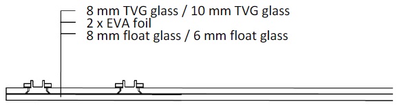
Two sets of equally sized laminated glass panels (Figure 1) were used in the experiment. The height of each specimen was 1335 mm and the width was 1000 mm. The specimens consisted of two glass plies bonded together with two layers of the EVA foil with the total thickness of 0,76 mm (0,38 mm each layer). The undrilled ply was made of float glass and the other one was made of heat strengthened (TVG) glass. The set I specimens consisted of two 8 mm glass plies. The set II specimens consisted of a 10 mm TVG glass ply and a 6 mm float glass ply. There were two sets of the embedded laminated connections in the lower part of the panels (four in total). Two HDPE (high density polyethylene) liners prevented the direct contact between the glass ply and the steel element.
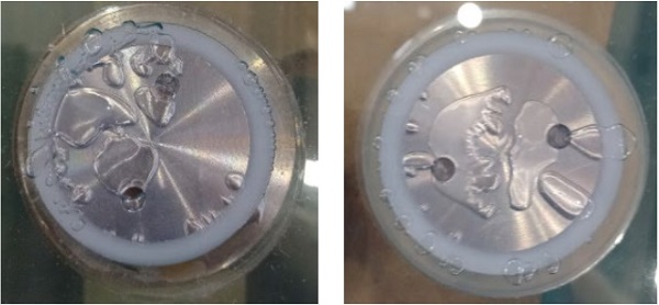
Before the experiment, the specimens were checked in order to reveal manufacturing defects, mainly the bubbles (Figure 2). The bubbles should not influence the performance of the connection. However, they are unacceptable for aesthetical reasons.
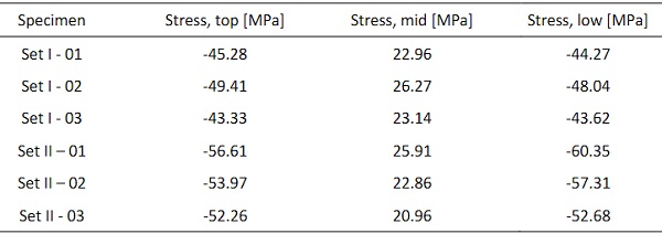
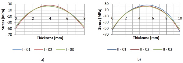
The compact scattered light polariscope (SCALP) was used to measure the depthwise stress of the TVG glass panes of all specimens (Table 1). Graphs in the Figure 3 represent the distribution of stresses of the TVG glass plies depending on the thickness.
Table 1: Stresses measured by SCALP in TVG glass plies.
2.2. Arrangement of the experiment
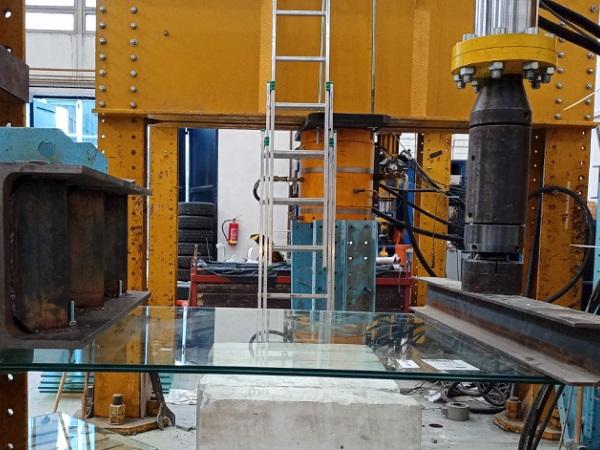
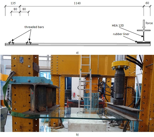
During the experiment, the samples were horizontally suspended using the threaded bars. The load was applied by a single hydraulic jack and distributed to the specimens by a 1200 mm long HEA 120 steel beam placed on a rubber liner. The rubber liner prevented a direct contact between the steel beam and the glass panel. The load was transferred along the upper edge of the inner ply (the drilled ply) of the banister panel (Figure 4).
2.3. Course of the experiment
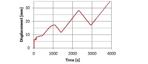
First of all, the specimens were loaded by the weight of the steel beam. When the deflection stabilized, the load introduced by the hydraulic jack was applied in two loading and unloading cycles. The loading was controlled by the jack displacement. Prior to next step, the displacement was kept on a constant value for 30 s. Then it was continuously increasing until the collapse (Figure 5). Loading was performed at constant speed of 1 mm/min. During the experiment, deflections in the area of the connections and deflection at two corners of the loaded edge were measured. There were two expected modes of failure. The glass pane could fracture due to reaching the tensile resistance limit caused by bending, or the TVG glass ply might fracture in the area of connection.
2.4. Results and comparison
Majority of set I specimens collapsed while reaching a certain value of displacement. The heat-strengthened glass ply fractured due to reaching the tensile strength limit (Figure 6a). The float glass ply remained undamaged and the connections did not collapse; the banister panel remained on its place. In one case, the heat-strengthened glass fractured in the area of connection (Figure 6c). It was a spider-shaped fracture possibly caused by a manufacturing defect. One of the fractured specimens was left loaded by the steel beam for 48 hours. During this period, the deflection of the banister panel increased and the float glass ply fractured as well (Figure 6b). No connection collapsed (Figure 6c).
All set II specimens collapsed in a same way. Both glass plies fractured at the same time when reaching a certain value of displacement due to reaching the tensile strength limit. No connection collapsed.
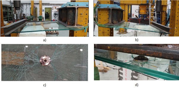
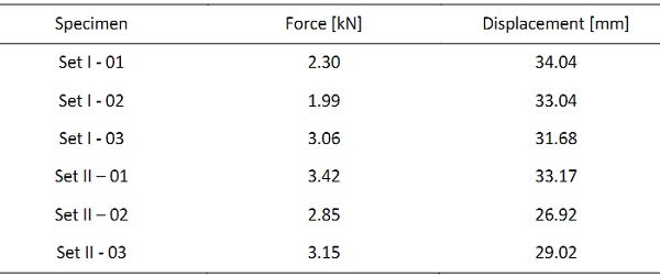
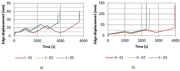
Table 2 compares the displacements and forces of the specimens right before the fracture. The measured data imply there was no significant displacement in the area of the connections. Moreover, the displacements of the edge and forces were around the same range regardless the type of the specimen. On the other hand, graphs in the figure 7 show a clear difference in the loading schemes.Only one set II specimen was capable to withstand both loading and unloading steps. Set II specimens also evince higher post-breakage deflections due to a thicker float glass ply.
Table 2: Results.
3. Conclusion
In order to verify knowledge obtained from previous small-scale experiments, two sets of banister panels with four embedded laminated connections were tested. Short-term load bearing capacity and a mode of failure were revealed as well.
Generally, both tested types of banister panels proved the ability to stay on its position after the fracture of glass as the connections did not fail. However, the forces and displacements loading to the fracture seem to be lower than expected and needed for the application. While comparing the obtained results, set I specimens appear to be more promising.
Further research including more tests and numerical modelling should be performed to determine the exact terms of failure.
Acknowledgements
This paper was prepared with a support of grants Hidden Connection of Laminated Glass Panes No. TH 03010175 of the Technology Agency of the Czech Republic (TAČR) and SGS of the Czech Technical University SGS22/140/OHK1/3T/11. The authors would like to thank OGB s.r.o for the cooperation and providing of the samples.
References
Bedon, C., Santarsiero, M.: Transparency in Structural Glass Systems Via Mechanical, Adhesive, and Laminated Connections -Existing Research and Developments. Advanced Engineering Materials (2018) https://doi.org/10.1002/adem.201700815
Cruz, P.J.S., Carvalho, P.L., de, Silva E., Casal C.: Embedded Glass Fixing System – Characterization and Conceptual Validation. Engineered transparency. International Conference at glasstec, Düsseldorf, Germany (2010)
Cruz, P.J.S., Carvalho, P.L. , Silva E., Rocha P.: Embedded point fittings in laminated and double insulating units. Challenging glass 4 & COST action TU0905 final conference: proceedings of the challenging glass 4 & cost action TU0905 final conference, Lausanne, Switzerland (2014) https://doi.org/10.1201/b16499-49
Haldimann, M., Luible, A., Overend,M.: Structural use of glass. Zurich, Switzerland: International Association for Bridge andStructural Engineering (2008). ISBN 3857481196
Zdražilová, M., Sokol,Z., Eliášová, M.: Tests of the Embedded Laminated Glass Connection Under Short-term Tensile and Eccentric Shear Loads. Challenging Glass 7, Ghent University (2020) https://doi.org/10.7480/cgc.7.4471
CertBond - COST Action CA18120
This paper was presented as part of a special session organised at Challenging Glass Conference 8 by the CertBond Cost Action CA18120 “Reliable roadmap for certification of bonded primary structures”.