
First presented at GPD 2019
Clearly, the VIG product must exhibit good durability over a service lifetime that would be greater than 25 years, this in particular for applied thermal loads. This paper shows that the stress levels within the VIG can be determined with good reliability and highlight the process that should be considered in the design and application of the VIG product.
1. Introduction
Progressively the architectural perspective on the visual design of commercial, and residential, buildings has led to the greater application of the transparent element in construction; glass. Since the increase in the surface area of glass in building façades, the impact of the ‘window’ thermal performance on the energy efficiency of a building has become an area of greater discussion. The IPCC reports since 2014 have highlighted the significant negative impact building energy use has on climate change1.
Conversely, the outcome of which is the greatest positive impact on climate change mitigation. There are numerous contributions to building energy use, nevertheless, the greatest waste is attributed to the uncontrolled heat loss that occurs through the window elements over the building envelope2,3. To improve the energy efficiency of buildings reducing energy loss through the window elements is an absolute must.
Traditionally, heat loss through windows has been accomplished by either a low emittance coating on a single pane of glass, or by use of double/triple layered gas filled windows.
In general, when the more insulating window is used, the centre-of-glass, air-to-air thermal conductance (U-value) can be as low as 0.6 W m-2 K-1 which is much lower than the U-value of a single pane of glass, about 6 W m-2 K-1. However, the traditional gas filled insulating window has an issue of cost, weight, overall thickness, and durability, that makes it unattractive, especially in residential retrofits. A novel alternative insulating window technology is the Vacuum Insulating Glazing (VIG).
This glazing consists of two panes of glass separated by a sub-millimetre evacuated gap between two panes of float glass. An array of spacers located in the gap maintains separation of the glass panes under atmospheric pressure. Over the past thirty years a considerable amount of work has been reported underlining the advances and advantages of the VIG technology4-14. The single most important outcome is that the design scope of the VIG product is wide, and highlights the potential for a U-value as low as 0.2 W m-2 K-1.
The thermal properties of a VIG is highly dependent on its design and application. Furthermore, the VIG product, during its service lifetime, is exposed to not only the continuous action of atmospheric pressure, but also temperature differentials. This paper looks to review the origin of temperature induced stresses in the VIG and presents analytical and finite element modelling data to highlight the fundamental factors which influence the magnitude and distribution of these stresses.
2. The origin and extent of thermal stresses
The outside of a building is exposed to varying weather conditions, where in some cases the winter conditions are severe with temperatures as low as -30 °C. The room side environment, however, is dominated by human needs and well regulated. This difference in temperature between the inside and outside of a building results in a thermal load, which is of particular interest when designing thermally insulating windows.
For the VIG, this thermal load is of fundamental importance in defining durability over a +25 year service lifetime. Simply, the thermal load produces stresses that are directly related to the thermal expansion of the two glass sheets relative to their bonded edges. In this paper, the VIG construction of concern is one that uses a rigid and fixed edge seal, such as that which results when using solder glass to form the edge seal7.
The external surface temperatures of a window are highly dependent on its thermal conductance, on the heat transfer from the inside environment to the glass surface and heat transfer from the glass sheet to the outside environment. Specifically, the U-value is defined as a measure of the thermal transport from the internal environment, through the window, to the external environment, in units of W m-2 K-1.
The heat transfer coefficient between the external/internal environments and the glass surfaces is defined by the coefficients he and hi, respectively, in units of W m-2 K-1. The hevalue in today’s standards is always assumed to be higher than the hi-value, due to a higher convection contribution from forced air flow; wind. Normally the heat transfer coefficients are assumed constant over the surfaces of the VIG. In this paper, however, modelling data for non-uniform heat transfer coefficients over the glass surfaces are also presented.
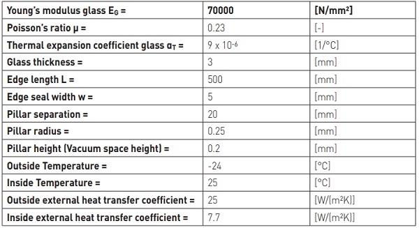
Collins et al developed an analytical model for spherical bending of the glass sheets in a VIG, to estimate the magnitude of the tensile and compressive stresses on the glass surfaces6. In the following discussion the results of the analytical model and finite element modelling are presented. The characteristics of the VIG unit, which was analysed with the analytical and finite element models, are in accordance with DIN 18008-1 and shown in table1. The environmental boundary conditions are in accordance with the European standards DIN EN 1991-1-5 and DIN EN 673 for severe winter conditions.
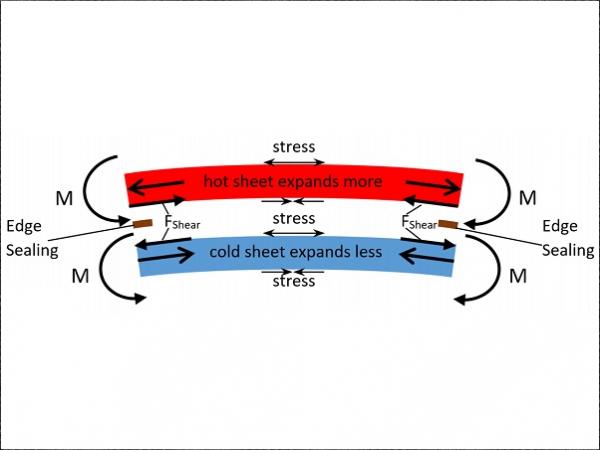
To highlight the stresses due to the thermal loads, in all cases to be discussed in the following sections, the stress field due to atmospheric pressure has been subtracted from the plots. A temperature load on a window is established as soon as it is installed in a closed façade of a building where the room-side and the outside environment temperatures are not equal. When the temperature difference is established the hot glass pane and the cold glass pane expand and contract, respectively.
If at the edge the glass sheets cannot move relative to each other, shear forces are established along the bonded edge seal on the contact surface between each internal surface and the edge seal. The consequence of this are tensile and compressive stresses over the cold and hot glass panes, respectively, result as shown in figure 1. These forces act over a distance of half the glass pane thickness, to the midplane of each pane, and create unidirectional moments in both glass sheets, which result in bending of the VIG unit.
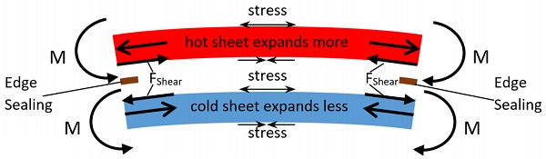
As the VIG unit bends under the action of the thermal load, the unit bends in the direction of the hot environment and stresses result on the external surfaces of the hot glass sheet and the cold sheet, in the form of tensile and compressive stresses, respectively, and on the internal surfaces in the opposite sense. The stresses on the internal cold surface are twice as large as those on the external hot surface as shown in figure 3. In general, the probability-of-failure of the glass, for an equivalent stress distribution, is two to three orders of magnitude lower on the vacuum side due to dry (no water) environment15.
The stress field of most interest for the potential failure of the glass sheets occurs near the edge seal, on the external hot glass surface parallel to the unit edge. The edge region bending is cylindrical and the tensile stresses parallel to the edge are about 3 times higher than the isotropic stresses away from the edge, according to the analytical model of Collins et al6, see figure 3.
However, the total thickness at the edge seal of the VIG also has a stiffening effect on the whole structure, which acts to reduce the overall bending. This stiffening effect at the edge reduces the maximum edge stress and is dependent on the edge seal width and length, as can be seen from second term of equation 1.
The total stress field induced in the VIG is due to two separate mechanisms. The first is the temperature difference established across the VIG unit, between the hot and cold environments that the unit faces. In equation 1 this is the first term on the left and is dependent (relative to temperature) on ∆Tave, where Tave is the average of the temperature field over the surface of the glass panes.
As shown in figure 1, this temperature difference results in bending and the resulting stress field through the glass panes, where the rigid edge seal and the non-linear bending of the glass panes act to reduce the overall magnitude of the stress. The second process is effectively an induced strain in the glass panes because of the difference in temperature between the edge seal and the centre-of-glazing.
If the mean temperature Tmean of both external surface temperatures of the VIG differs from the edge temperature Tedge, then inplane thermal expansion varies between the edge region and the centre-of-glazing. The additional stresses that result are parallel to the edge seal and comparable with the “hoop” stresses, considered by the last term in eqution1, that occur in conventional double glazing due to the highly conductive edge spacer. The total of the magnitude of stress induced due to these two processes is best represented by equation 1:
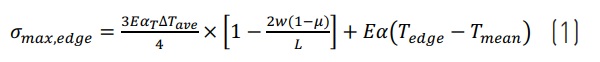
where all variables are as described before and E, αT and µ are the Young’s modulus, the thermal expansion coefficient and the Poisson’s ratio, respectively.
3. Results and Discussion
In the following section analytical and finite element data of the stress field induced in a VIG unit are presented. The analytical model, however, can only be applied for a VIG unit in a completely free edge configuration. This is, in most cases, not the desired boundary condition for a VIG unit, since a framed configuration would provide some constraint at the edge, if not completely constrain the edge of the unit.
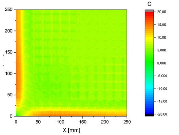
Nevertheless, the finite element model is used to investigate both the free and fixed edge configuration. Using symmetry arguments, a geometrically simplified model was used, with all edge seal and pillar contact process included in the model. Figure 2 is a contour plot of the first principle stress field, of a quarter surface area near a corner of a VIG for the free edge configuration of the external surface on the hot side of the VIG unit (surface 4).
The unconstrained edge configuration shows that the maximum stress in a VIG unit occurs parallel to the edge. For the fully constrained edge configuration the stresses on surface 4 are smaller. The maximum stress, for the fully constrained edge configuration, occurs at the corner of surface 2. The failure probability of a VIG unit due to stresses on the internal surface is much lower, because the surface is within the dry vacuum environment15. Therefore, the case of most interest for the failure of a VIG, is the free edge configuration.
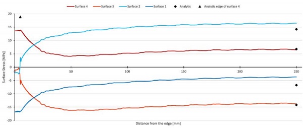
In the following the data is presented for the stress component parallel to the VIG edge. Figure 3 is a plot of this stress component for each of the glass surfaces; the usual notation of surface 1,2,3 and 4 is used, for the surfaces from the cold to the hot environment. In this figure the maximum tensile stress occurs at the edge of the unit on surface 4.
Even though the stress at the centre of the glazing is similar, and for greater temperature loads could be greater, surface 2 is to the vacuum gap, and as mentioned the dry vacuum environment results in a much lower probability of glass fracture15. Clearly, the analytical and finite element model results are in good agreement, and the maximum edge stress on surface 4 is about 3 times larger than the maximum centre-of-glazing stress.
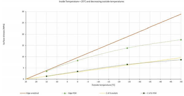
When the thermal load across the VIG unit increases, the induced stresses will increase. Figure 4 is a plot of the maximum edge, and centre of glazing, stress on surface 4 as a function of the thermal load across the VIG. At low temperature loads the analytical and FEM results are in good agreement. For larger loads the results diverge, this is due to the non-linear bending of the unit. It is clear that by definition the analytic calculation assumes linear behaviour.
There is also the same effect when considering changes due to the size of the VIG unit. Figure 5 shows that the analytical calculation predicts an increase in stress up to a unit size with an edge length of 1 m, and then a steady state is reached. However, as with the non-linear effect for the temperature load, the reduced bending at larger unit sizes produces a decreasing stress at the edge for a unit size with an edge length greater than about 300 mm.

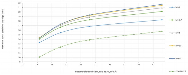
When the external heat transfer coefficients of the glass surfaces change, the resulting stress induced in the glass also changes. This is clearly the case since the heat transfer coefficients define the temperature field on the glass. Figure 6 is a plot of the surface 4 edge stress for different combinations of the heat transfer coefficients. For a greater difference in the heat transfer coefficients, the resulting edge stress is greater.
In the discussion thus far, the VIG unit is assumed to be under the action of a uniform heat transfer field across the glass surfaces. However, in the service life application it is most likely that many factors will influence the heat transfer to the glass surface, effectively producing a non-linear heat transfer coefficient between the external environments and the glass surface. This is a non-trivial condition to study, since the potential variants are great.
Here we assume a single simple case to study; that is, the external glass surface to the cold environment has nonuniform convection which leads to a different heat transfer coefficient over a perimeter edge region on the glass relative to the remaining centre area of the glass. In particular, we assume that forced convection closer to the edge is lower. That is, the wind velocity on the surface of a built-in (framed) glazing varies with the frame geometry or the location of the window in the façade. In all cases, the wind speed at the edge is lower, with respect to the centre of the window16.
To model this case two heat transfer coefficients were employed on the glass surface (surface 1); over an outer perimeter area 100 mm and 25 mm in width, labelled as he,o and varied from 10 W/m-2K-1 to 25 W/m-2K-1 and for the remaining glass surface area on surface 1, the heat transfer coefficient labelled he,i fixed at 25 W/(m²K) was employed. The heat transfer coefficient on surface 4 was constant over the entire surface and set to 7.7 W/m²K. The resulting stress field on surface 4 is presented in figure 7(a) and (b).
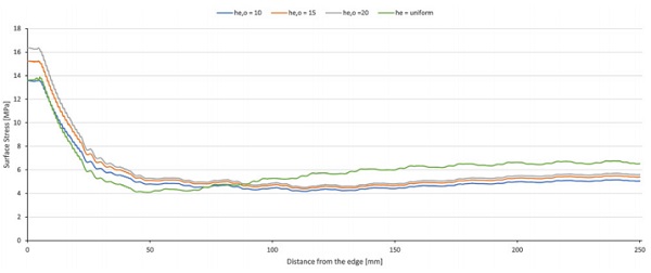
The data indicate that for a non-uniform heat transfer coefficient on surface 1, the stress at the centre of the glazing is lower than that compared to the stress resulting from a uniform he over the surface. For small differences between he,I and he,o the edge stress is higher than that compared to the stress resulting from a uniform value of he. The perimeter area was also investigated for a width of 25mm shown in figure 7b.
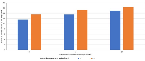
For both width of the outer area, 100mm and 25 mm, a difference of 5 W m-2K-1 between he,o and he,I lead to an increase of the maximum stress parallel to the edge. This is assumed to be contributed by an increase of the hoop stress. An edge covering frame would also have the effect of a lower heat transfer coefficient in the edge region. Therefore, further investigations are planned and will be published in a future paper.
4. Conclusion
The results presented in this paper are for a VIG unit with the properties defined in Table 1. All material properties and environment conditions were defined in accordance with DIN 18008-1, DIN EN 1991-1-5 and DIN EN 673.
The main results of this work show that,
- The stress of most interest for the failure of a VIG occurs on surface 4 parallel to the edge for the unconstrained edge configuration
- In general, the analytical and finite element data are in good agreement
- There is a non-linear bending effect which limits the magnitude of stress in units that experience a large temperature load and/or are large in size
- The maximum edge stress in a VIG increases with increasing heat transfer coefficients on the external surfaces
- A non-uniform heat transfer coefficient does result in changes in the temperature field and the induced stresses
References
1 International Panel for Climate Change, 4th and 5th Assessment Report – Summary for Policy Makers
2 D. Arasteh, S. Selkowitz, and J. Wolfe, The design and testing of a highly insulating glazing system for use with conventional window systems, Journal of Solar Energy Engineering, 111, 44-53, 1989.
3 L. Pérez-Lombard, J. Ortiz, and C. Pout, A review on buildings energy consumption information, Energy and Buildings, 40, 394-398, 2008.
4 R. E. Collins, G. M. Turner, A. C. Fischer-Cripps, J.-Z. Tang, T. M. Simko, C. J. Dey, D. A. Clugston, Q.-C. Zhang, and J. D. Garrison, Vacuum glazing – A new component for insulating windows, Building and Environment, 30[4], 459-492, 1995.
5 T. M. Simko, A. C. Fischer-Cripps, and R. E. Collins, Temperature-induced stresses in vacuum glazing: Modeling and experimental validation, Solar Energy, 63[1], 1-21, 1998.
6 R. E. Collins, A. C. Fischer-Cripps, and J.-Z. Tang, Transparent evacuated insulation, Solar Energy, 49[5], 333-350, 1992.
7 R. E. Collins and T. M. Simko, Current status of the science and technology of vacuum glazing, Solar Energy, 62[3], 189-213, 1998.
8 P. C. Eames, Vacuum glazing: Current performance and future prospects, Vacuum, 82[7], 717-722, 2008.
9 P. W. Griffiths, M. di Leo, P. Cartwright, P. C. Eames, P. Yianoulis, G. Leftheriotis, B. Norton, Fabrication of evacuated glazing at low temperature, Solar Energy, 63[4], 243-249, 1998.
10 S. Papaefthimiou, G. Leftheriotis, P. Yianoulis, T. J. Hyde, P. C. Eames, Y. Fang, P.-Y. Pennarun, P. Jannasch, Development of electrochromic evacuated advanced glazing, Energy and Buildings, 38[12], 1455-1467, 2006
11 J. F. Zhao, P. C. Eames, T. J. Hyde, Y. Fang, J. Wang, A modified pump-out technique used for fabrication of low temperature metal sealed vacuum glazing, Solar Energy, 8[9], 1072-1077, 2007.
12 H. Manz, S. Brunner, and L. Wullschleger, Triple vacuum glazing: Heat transfer and basic mechanical design constraints, Solar Energy, 80[12], 1632-1642, 2006.
13 L. Wullschleger, H. Manz, K. Ghazi Wakili, Finite element analysis of temperature-induced deflection of vacuum glazing, Construction and Building Materials, 23[3], 1378-1388, 2009.
14 M. M. Koebel, H. Manz, K. E. Mayerhofer, B. Keller, Service-life limitations in vacuum glazing: A transient pressure balance model, Solar Energy Materials and Solar Cells, 94[6], 1015-1024, 2010.
15 Brian Lawn (1993): Fracture of Brittle Solids – Second Edition


Comments
It is amazing how far glass technology has come!!