This paper was first presented at GPD 2019 by Strömmer Esko, Tanskanen Antti and Keränen Kimmo from VTT Technical Research Centre of Finland Ltd, Finland.
When compared to the existing WPT systems such as those based on the Qi low power specification of the Wireless Power Consortium, the main differences of the technical implementation for better applicability to glass laminate applications are a novel self-regulating antenna tuning solution and relatively high (6.78 MHz) operation frequency. The self-regulating antenna tuning solution keeps the receiver output voltage nearly stable and maintains high efficiency by keeping the antennas in resonance with variable loading of the power receiver.
The WPT system is based on a class-D topology RF inverter at the power transmitter side. The safety of the WPT system to nearby humans and electrical devices is ensured by ferrite shielding of the antenna coupler. The performance of the WPT system has been evaluated by theoretical analysis, circuit simulations and a preliminary experimental system. The simulations show 57 % total DC-to-DC power transfer efficiency with the nominal 30 W receiver output power, which probably can be improved by refining the design of the RF inverter.
Introduction
The progress in material and manufacturing technologies has enabled the implementation of electronics with completely new features. In addition to the rigid silicon based electronics, flexible, deformable and large area electronics has become a reality. As a part of this technological development, glass laminated electronics has become an interesting enabler for the products relevant to the fields such as architecture and automotive.
Printed hybrid electronics integration inside glass laminates utilizes the latest knowhow of materials and manufacturing technologies. In this approach, the electronics is not only covered by glass, but it is embedded as a solid functional system within the glass laminate, resulting in different implementations from the conventionally glass protected devices such as solar panels or displays.
In the Flex-in Glass R&D project, we have studied and developed several electronic and photonic functionalities embedded inside glass laminates. Already demonstrated functionalities include lighting, displays, sensing and wireless communication, all wirelessly powered through the glass laminates to facilitate environmental shielding of the embedded functionalities against dust, moisture and chemical contamination.
Lighting, sensors and electronics targeted to be integrated in laminated glass structures are also introduced in [1], [2] and [3]. However, publications introducing wireless power transfer (WPT) capable of supplying high power for mentioned functionalities are lacking. In this paper, we introduce a safe, high efficiency, small size WPT system with extremely thin power receiver capable of supplying up to 30W electric DC power for lighting, display, sensing and communication functionalities.
Among the requirements of the wireless powering, safety to nearby humans is considered as number one. The system has also be safe to nearby devices, i.e. the RF emissions must not damage nearby electrical devices. High efficiency is required in order to save energy and to avoid excess heating of the system that may increase the failure rate. Small size is important to avoid degrading of the visual appearance, and extremely thin structure (1 mm or less) is necessary to enable the integration into thin laminated glass systems.
Technical implementation
Figure 1 presents a generic physical level model of a WPT system based on inductive near field coupling. The right side of the diagram represents the wireless power receiver. The left side of the diagram is the wireless RF power transmitter that involves an RF inverter for generating RF power from DC supply power, and an antenna tuning network for matching the RF inverter with the effective complex load impedance of the antenna coupler.
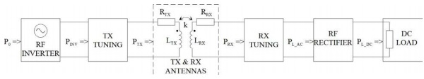
The right side of the diagram is the wireless RF power receiver that involves a DC load for modelling the power extraction to the target application to be powered, an RF rectifier for generating DC power from the received RF power, and an antenna tuning network for matching the antenna coupler with the effective complex load impedance of the receiver.
The antennas are modelled by their lumped circuit parameters LTX (power transmitter antenna inductance), LRX (power receiver antenna inductance), RTX (equivalent serial resistance modelling the power loss in the transmitter antenna), RRX (equivalent serial resistance modelling the power loss in the receiver antenna), and k (inductive coupling coefficient between the antennas).
In the Flex-in Glass project, a novel wireless power transfer (WPT) arrangement has been developed and preliminary demonstrated. When compared to the existing WPT systems such as those based on the Qi low power specification of the Wireless Power Consortium (WPC) [4], the main differences and the other basic features of the technical implementation for better applicability to glass laminate applications are the following:
- Antenna tuning: The technical implementation is based on a novel self-regulating antenna tuning solution. One basic facility of this antenna tuning solution is keeping the power transmitter and the power receiver in resonance even with variable receiver load and antenna coupling, thus maintaining high efficiency in all conditions. Another basic facility is keeping the receiver output voltage nearly stable with variable receiver load, provided that the RF inverter gives constant output voltage with variable output power and the coupling between the antennas is constant, which is evident for the target application that features fixed mutual alignment of the antennas. This inherent self-regulation feature is purely based on inductive coupling between the antennas and does not require any active control of the RF inverter that is based on signalling from the power receiver to the power transmitter as in the Qi systems. An advantage of this inherent selfregulation feature is rapid adaptation of the RF inverter output power to the receiver output power, which together with the relatively high operating frequency enables stable output voltage of the receiver with a rectifier capacitor that can be small enough to be fitted inside the glass laminates.
- RF inverter: The RF inverter has to be able to give enough power that covers the power taken out from the receiver and the power losses of the rectifier, antennas and the tuning circuits. As stated above, the selfregulation feature of the power transfer system requires keeping the RF inverter output voltage constant with variable output power. For these reasons, Class-D amplifier topology with fixed supply voltage, producing square-wave output waveform, was selected for the baseline solution of the RF inverter.
- Operation frequency: The selected operation frequency is 6.78 MHz, which is remarkably higher than that of the current commercial Qi specification based WPT systems. The higher frequency enables antennas with smaller diameter and lower number of turns. The higher frequency also enables the use of thin (e.g. 35 µm) PCB track antennas instead of the thicker litz wire antennas that are typically applied in Qi WPT systems. Moreover, 6.78 MHz is in line with the regulation ITU-R SM.2110-0 (September 2017), in which the International Telecommunication Union (ITU) recommends that administrations should consider as a guideline the use of the frequency range 6.765 – 6.795 MHz for the operation of non-beam wireless power transfer systems [5]. The disadvantage of the higher operation frequency is the degraded efficiency of the RF inverter, which can partly be compensated by improved antenna efficiency due to higher antenna Q factors.
- Ferrite shielding: The antenna coupler is covered by two ferrite shields on the outer surfaces of the transmitter and the receiver antenna. The relatively high operation frequency decreases the total magnetic flux through the antennas and thus enables thinner ferrite shields, which is important especially at the receiver that has to fit into the glass laminates. The ferrite shields are not absolutely necessary because of the relatively small antenna diameter that makes the field emissions to damp rapidly with the increasing distance from the antenna coupler. Without ferrite shields, additional measures to guarantee the human safety in all conditions would however be necessary.
Theoretical performance analysis
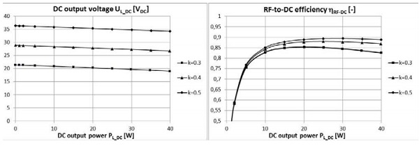
The performance analysis of the Flex-in Glass WPT system is based on linear circuit analysis by lumped parameter circuit model with linear approximation of the non-linear components. The antenna Q-factors were set to 75, which was based on the earlier experience of similar antennas. The nominal coupling coefficient between the antennas, used for calculating the optimal antenna inductances and the optimal tuning capacitances and inductances, was set to 0.3. The RF inverter output voltage was 48 VPP square wave.
The calculated DC output voltage of the power receiver and the RF-to-DC efficiency (PL_DC / PINV in Figure 1) with antenna coupling coefficients 0.3, 0.4 and 0.5 and with variable loading of the receiver is shown in Figure 2. The DC output voltage graph implies the self-regulation feature of the system, i.e. the receiver output voltage is rather independent of the receiver loading. The receiver output voltage depends on the coupling coefficient, but this is not critical in the target application, in which the antenna coupling coefficient can be fixed. The RF-to-DC efficiency graph implies 82 – 90 % efficiency with 10 – 40 W DC output power and antenna coupling coefficients 0.3 – 0.5. The RF inverter losses that are difficult to be theoretically estimated are however not included in these figures.
Performance simulations
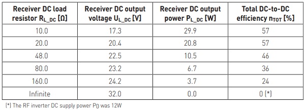
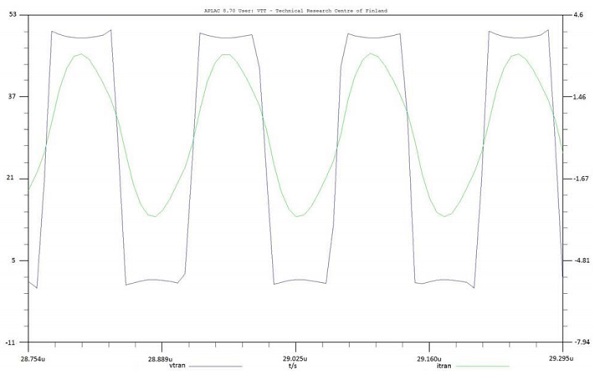
The performance of the Flex-in Glass WPT system was simulated by APLAC 8.70 circuit simulator by using a 50 VDC supply, a class-D topology RF inverter and a full-bridge rectifier with PMEG3050EP Schottky diodes. Contrary to the theoretical analysis, the simulations also addressed the losses of the RF inverter. The coupling coefficient between the antenna coils was 0.3 and the antenna Q-factors 75. The simulated receiver DC output voltage, receiver DC output power and total efficiency with various DC loads are shown in Table 1.
The results indicate again intrinsic self-regulation feature of the WPT system maintaining nearly constant DC output over wide range of DC loads, while the maximum efficiency is achieved near the nominal power of 30 W. The simulated voltage and current graphs at the output of the RF inverter in the power transmitter with a 10 Ω DC load resistor at the receiver output are shown in Figure 3. The phase shift between the voltage and the current is close to zero, which indicates the resonance of the power transmitter.
Preliminary experimental system
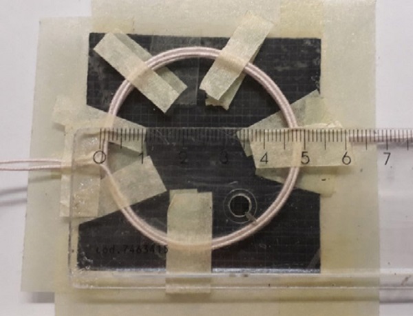
The theoretical analysis was verified by an experimental system with similar 50 mm antennas in the power transmitter and in the power receiver on the opposite surfaces of a 4 mm glass plate (Figure 4). The outer surface of both antennas was covered by a 60 mm x 60 mm x 0.43 mm ferrite sheet. Both antennas involved two loops of 1.1 mm thick litz wire, which in the forthcoming implementations can be replaced by trace loop antennas on a thin PCB to achieve the 1 mm total thickness of the power receiver with the ferrite shield.
The power receiver involved a full-bridge rectifier implemented by four Schottky diodes (PMEG3050EP) and a 1 µF ceramic chip capacitor. The DC power extraction from the receiver was accomplished by one, two or three 47 Ω power resistors in parallel. At the power transmitter side, the class-D RF inverter was emulated by a commercial HF transceiver Icom IC-720A that was adjusted to feed 60 VPP sine wave (corresponding 47 VPP square wave from the class-D inverter) into the transmitter antenna tuning network.
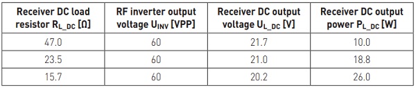
The received DC output voltage (measured by a multimeter) and DC output power (calculated from the previous) with three different receiver load resistors are presented in Table 2. The results are well in line with the theoretical analysis, and the self-regulation feature of the output voltage is evident.
Discussion and conclusions
A novel wireless power transfer (WPT) system capable of supplying up to 30 W electric DC power for lighting, display, sensing and communication functionalities inside glass laminates was designed. The main requirements arising from the target application are small size, extremely thin (1 mm or less) power receiver that fits inside glass laminates, high efficiency and safety.
These requirements were addressed by a novel antenna tuning solution that combined with a class-D topology RF inverter accomplished self-regulation of the power receiver output voltage, remarkably higher operating frequency than in the existing commercial wireless charging solutions, and ferrite shielding of the antenna coupler.
The performance of the WPT system was evaluated by theoretical analysis, circuit simulations and a preliminary experimental system. The theoretical analysis was based on linear circuit analysis with linear approximation of the non-linear components and excluded the RF inverter. The circuit simulation model involved the entire WPT system with the class-D RF inverter. In the preliminary experimental system, the RF inverter was replaced by a commercial HF transceiver that was adjusted to feed 60 VPP sine wave into the transmitter antenna tuning network. The circuit simulation gave a total power transfer efficiency 57 % with receiver DC output power levels 20.8 W and 29.9 W.
The corresponding efficiency with the theoretical model by excluding the inverter was about 85 %. In addition to the exclusion of the RF inverter losses, the higher efficiency with the theoretical model can be accounted for the inaccuracy of the rectifier losses that cover only the losses due to the diode forward threshold voltage. In spite of this, the major part of the losses in the final implementation can be expected to be caused by the RF inverter. Thus, refining the inverter design is the most important issue in further improvements of the efficiency. This may also favour lower operation frequency of the WPT system to reduce the switching lossess of the inverter, provided that the operation frequency is kept high enough to keep the annenna coupler compact enough.
The theoretical model and the simulation model indicated clearly the resonance of the power transmitter with variable load. The self-regulation feature of the receiver output voltage can be clearly seen by each performance evaluation method. In the simulations, a substantial increase of the output voltage was observed without any load resistor (infinite RL_DC), which probably is related to the non-linear behaviour of the RF rectifier and possibly also the RF inverter. This can be compensated by maintaining continuously a small load at the receiver output.
References
[1] ”Laminated glass and glass structures with lighting, sensors and electronics”, US 2005/0233125 A1.
[2] “Capacitive rain sensor for windscreen”, US 2000/006094981 A.
[3] “Laminated glass pane assembly with electrically controllable reflectance and method of making said assemblies”, US 2001/6259549 B1.
[4] Wireless Power Consortium homepage, https://www.wirelesspowerconsortium.com/.
[5] “Frequency ranges for operation of non-beam Wireless Power Transmission (WPT) systems”. Recommendation SM.2110-0 (09/2017), International Telecommunication Union (ITU), 2017.