Source:
Challenging Glass 7
Conference on Architectural and Structural Applications of Glass
Belis, Bos & Louter (Eds.), Ghent University, September 2020.
Copyright © with the authors. All rights reserved.
ISBN 978-94-6366-296-3, https://doi.org/10.7480/cgc.7.4505
Authors:
Tomàs Colldecarrera
Jordi Torres
Arnau Bover

A simulation tool for simple flat and cylindrical insulated glass units (IGUs) has been developed using VBA code included on Excel and RF-COM, the programmable COM Interface for the RFEM of Dlubal. The software allows the non-linear computational analysis of rectangular flat panels and cylindrical IGUs considering the monolithic equivalent thickness of the inner and outer glass panel.
The sealant silicone elastic properties can be defined by the users, including, if necessary, the rotational stiffness. Climatic load and superficial uniform loads (typically wind loads) can be defined. The tool automatically generates the inner and outer glass panels with shell elements and the boundary conditions in RFEM. Both panels are connected all along the perimeter by means of spring elements with the equivalent stiffness of the silicone.
The internal pressure due to climatic loads and the distribution of the superficial uniform loads are automatically calculated by means of an iterative method. This method, published for other authors in the recent past, considers the bending stiffness of both glass panels and the silicone for the definition of the resultant load.
The results of the simulations have been successfully correlated with the commercial software SJ-MEPLA for flat panels and ANSYS Workbench 19.0 for flat and cylindrical panels, in this case, modelling the air cavity with a 3D hydrostatic fluid element (HSFLD242). The simulation tool provides an accurate definition of the internal pressure, deflection and stress on glass panels and forces through the sealant silicone with a reduced pre-post and calculation time, being ideal for parametric studies.
1. Introduction
Insulated glass units (IGUs) are the most widely used solution for envelope of modern buildings due to the combination between transparency, light transmission and thermal insulation. The modern architecture is also demanding challenging envelope shapes which can be solved by cylindrical, spherical or free form panels. The non-flat IGUs add complexity to the design and verification. The higher bending stiffness of the panels due to the shape allows a higher span between supports but it also increases drastically the internal pressure due to climatic loads.
Flat IGUs can be accurately designed with commercial software as SJ-MEPLA or GLASGLOBAL of Sommer Informatik. Also, as alternative it is possible to use the formulation included in (Feldemeier 2009; DIN 18008-1 2010, DIN 18008-2 2010; PrEN 16612 2017) which determines the sharing load between packages in case of uniform external load and, also, the climatic load.
Nevertheless, non-flat panels have to be simulated using special elements featured by advanced finite element analysis software as ANSYS or manual iterative procedure with other general propose simulation software. The pre-process complexity and long calculation time using ANSYS, makes this solution suitable for an accurate design of a few panels if necessary. However, in case of a project with several types of glass panels, parametric studies or design estimations in early project stages, this simulation technique is not a functional solution.
As alternative, it is possible to develop an iterative procedure in order to determine the internal pressure variation due to climatic load. Recently publication such as (Marinovet Griffith 2015, Baoet Gregson 2019) defines the formulation in order to take into account the glass panels bending stiffness and the secondary sealant silicone stiffness. In both reference the iterative procedure is applied by a combination of geometric definition with Rhino+Grasshopper and finite element simulation with Strand7.
The simulation tool described in this paper is based on the methodology developed in the aforementioned references. However, in this case,the parametric tool is integrated in a single software by means of the programmable COM Interface for the RFEM of Dlubal. The paper contains (1) the background formulation defined in the bibliography, (2) the description of the methodology applied in the simulation tool, (3) the validation of the results obtained by the tool with SJ-MEPLA for flat panels and ANSYS for flat and cylindrical panels and (4) a parametric analysis showing the influence of the key parameters in the internal pressure and glass deformation variation due to climatic load.
2. Formulation
Climatic loads on insulating glass units can be caused by a change of exterior temperature, barometric pressure or a change of the altitude between fabrication and service conditions. As a consequence, a pressure difference between the exterior air and the cavity gas is produced:

where ∆T is the change of temperature in the cavity in K, ∆Pb is the change of barometric pressure in kPa and ∆h is the change of altitude between production and installation in meters.
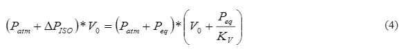
This pressure, named isochoric pressure,is defined as the differential pressure caused by a climatic change assuming that the cavity volume remains constant. However, due to the flexibility of the panels, this pressure produces a volume change in the gas chamber. Internal pressure and cavity volume change until reaching an equilibrium point, (Marinov et Griffith 2015, Bao et Gregson 2019):
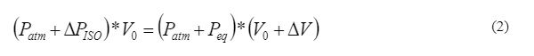
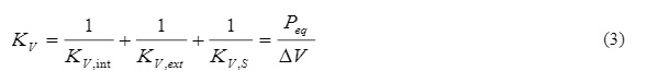
Volumetric stiffness KV is introduced to the equation. The relation of volume changes and the pressure is applied, which depends on both glass panes (KV, I, KV, E) and the sealing silicone (KV,S).
Equation 2 can be converted into a quadratic equation, and equilibrium pressure Peq solved.
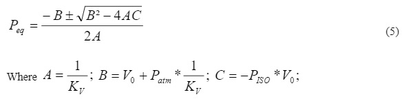
With the relationship between the equilibrium pressure (Peq) and the climatic load (P0) the insulating glass factor (φ) can be found. The insulating glass factor has values between 0 and 1. Flexible systems, e.g. large rectangular flat unit with thin glass panes, have a small insulating glass factor near 0. Stiff systems, e.g. small unit with thick glass panes or cylindrical panels with small radius, have an insulating glass factor near to the unit.

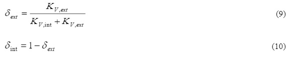
This insulating factor φ is also useful to determine the load distribution of a surface pressure (P) applied on the exterior pane according to DIN 18008-2. The load distribution on the glass panes is:
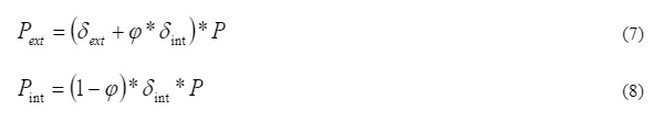
Where δ is the relative stiffness of the glass panes. This value is calculated using the glass thickness according to DIN 18008-2. However, for more accurate distribution the volumetric stiffness of both panels is considered.
3. Tool Description
The simulation tool allows the user to introduce the following parameters in an Excel spread sheet: The dimensions of the glass panes, the curvature radius, the glass and gas cavity thickness, Young’s modulus E and Poisson coefficient of the glass and the silicone, silicone bite, mesh size, climatic load (∆T, ∆h and ∆Pbar) and pressure load, boundary conditions (supported by 2 or 4 edges). Multiple models can be defined, submitted and main results are obtained in a row.
The program automatically generates the model according to the input parameters. The glass panels are modelled using shell element with a controlled regular mesh. The sealant silicone is modelled using definable stiffness bars that connect the nodes of the glass perimeter. The axial and shear stiffness of the silicone is automatically calculated considering the tributary length. The rotational stiffness can be also considered.
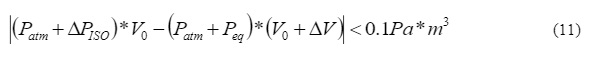
In the first step of the iterative process, the program applies an initial load which can be defined by the user. After the simulation, the ∆V is automatically calculated in order to determine the volumetric stiffness KV (Eq. 3) and the equilibrium pressure Peq (Eq. 5). The program defines iteratively the internal pressure until the following criterion is achieved.
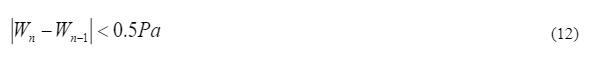
Once the climatic load is solved, the uniform load (typically wind load) is distributed by means of Eq. 7-10 with the insulating glass factor φ (Eq.6). The volume stiffness of each panel is automatically calculated. Notice that the silicone stiffness can influence the load distribution between panels, for example, if the panel is only supported by the inner pane and the sealant silicone connects the external and internal pane. Due to the non-linear performance of the glass panels supported along the 4 edges, the volumetric stiffness is iteratively adjusted until the difference of wind load distribution between iterations meets the criterion defined in Eq.12. Where Wn and Wn-1are the current and the previous iteration wind load distribution.
The simulation tool exports the key results during the iteration process to an Excel spreadsheet. The program provides the main results for every panel with the final load distribution and save the file for additional post-processing by the user.
4. Validation
4.1 Flat IGU
The simulation tool is validated with SJ-MEPLA 5.0.7 and ANSYS Workbench 19.0 for flat panels. A flat IGU of 2000x6000mm rectangular shape with a thickness for the external glass panes of 6mm and for an internal glass of 8mm is considered. Monolithic glass panels are considered for the sake of simplicity. The chamber thickness is considered 12mm and filled with air. Glass elastic modulus and poison coefficient are E=70000MPa and υ=0.23.
In order to simulate the spacer between panels, the values recommended by SJ-MEPLA are used: E=100MPa, G=0MPa and the bite b=5mm with linear compressive-tensile properties. Modifying the spacer properties did not change significantly the glass performance in this software. For the validation, the panel is defined supported by the four edges, uz=0, and isostatic in the plane.
Three load cases are calculated. (1) Surface uniform pressure on the exterior pane simulating a wind load of P=1100Pa (Pressure), (2) Temperature rise of ∆T= 50ºC. (3) The combination of both cases P=1100Pa and T=50ºC.
ANSYS allows to simulate the behaviour of fluids in closed cavities using the 3D hydrostatic fluid element HSFLD242 defined by 5 or 9 nodes. The element combines 4 or 8 nodes for the containing surface elements (lineal or nonlinear) with 3 degrees of freedom at each node. The pressure node, which position is defined by the user, can have 1 or 2 degree of freedom (Hydrostatic pressure and pressure). To model closed systems without fluid flow, only the hydrostatic pressure degree of freedom is considered.
This element does not require to be specifically meshed by the user. The element is well suited to calculate problems involving fluid-solid interaction as it can be an insulated glass unit. In this case, the enclosure elements are both glass panels and the sealant silicone. The gas is defined from its density at a pressure and temperature determined. Finally, the element outputs are the interior gas pressure, initial volume and final volume.
The silicone sealant is simulated using the Solid186 element (20 nodes with 3DoF), the material properties recommended by manufactured, E=3.045MPa and υ=0.49 and a silicone bite of 10mm. The mesh is refined all along the perimeter with 3 elements along the thickness of the silicone, giving an element size of around 4x4x4mm.
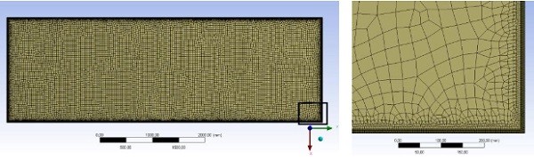
The glass panes are simulated using Shell181 elements (4 nodes with 6 DoF). The element size at the centre of the panels is 40x40mm, but the perimeter is refined to 4x4mm. The glass panels are mesh coincident. The inner glass panel is out-of-plane simply supported along the perimeter. The uniform load is applied at the external pane.
The type of elements of the model was benchmarked. The glass panes were also simulated using Shell181 and Solid Shell 190. The results were coincident with differences lower than 1%. This study is not included in this paper.
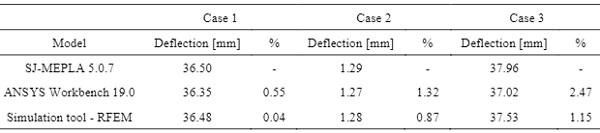
The main results obtained for the three methods are included in the following tables. For the sake of simplicity, the tables only show the pressure load applied to the inner glass pane and the deflection of the inner pane. Notice that under external uniform load the pressure is distributed (P=Pint+Pext) between both panels and under climatic load the same pressure is applied to both panels with opposite direction.
The relative equilibrium pressure and out-of-plane deflection of the simulation tool have a difference lower than 1.2% in comparison to the results obtained with SJ-MEPLA which are taken as a reference. The simulation with ANSYS trends to show slightly higher internal pressures but not bigger deflections. The differences are within an allow able range and they can be justified due to the different simulation technique and the modelling of the perimeter connection.
The calculation time used with by ANSYS is around 30 minutes, obviously depending on the work-station or server capacity. SJ-MEPLA is until 10 times faster, taking around 3 minutes, and the developed tool can solve the simulation with less than 60 seconds.
Table 1: Pressure applied on the inner pane. Flat rectangular model.
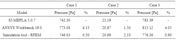
Table 2: Maximum out-of-plane deflection on the inner pane. Flat rectangular model.
4.2 Cylindrical IGU
A curved IGU of 2000x6000mm rectangular shape with radius of 12000mm with a thickness forthe external glass pane of 6mm and an internal glass pane of 8mm is considered. Monolithic glass panels are considered for the sake of simplicity. The cavity thickness is considered 12mm and filled with air. Glass and silicone mechanical properties are the same as the once defined for the flat panel in the previous section. The four edges of the bottom panel are simply supported along the radial direction.
Three load cases are calculated. (1) Surface uniform pressure on the exterior pane simulating a wind load of P=1100Pa (Pressure), (2) Temperature rise of ∆T= 50ºC. (3) The combination of both cases P=1100Pa and T=50ºC.
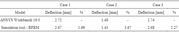
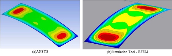
The results are only showed for the inner pane.When an external load is applied the load in the outer pane can be obtained with a direct subtraction of the total load. For climatic load both panels receive the same load in opposite direction. Both methods obtain similar results in terms of equilibrium internal pressure and deflection. ANSYS trends to calculate slightly higher internal pressure due to climatic loads, up to 8.6%. The deflections are also similar with a maximum relative difference of 3.7%, which corresponds to an absolute difference of 0.05mm.
The simulation tool automatically generates the complex geometry, in front of the time consuming pre-process of ANSYS Workbench. Moreover, the tool is able to solve the calculation with less than 60 seconds.
Table 3: Pressure applied on the inner pane. Cylindrical model.
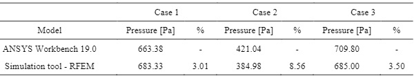
Table 4: Maximum deflection on the inner pane. Cylindrical model.
5. Parametric Study
The following parametric study has been carried out to demonstrate the capability of the simulation tool developed to run several calculations in a row. The results allow for quick design decision concerning the most relevant panel parameters.
The basic IGU for this parametric study is a curved 1500x3000mm rectangular shape, with radius of 10mand the thickness for both panels of 8mm. The chamber thickness is considered 12mm and filled with air and the silicone width is 10mm. In this case, only a climatic load case is considered with a temperature rise of ∆T= 50ºC. The isochoric pressure is 17 kPa.
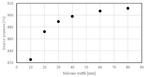
The following geometric variables have been included in this paper: the curvature radius is considered between 3m to 30m, the glass thickness is considered between 6 to 60mm, and the sealant silicone width between 10mm to 80mm.
The silicone is considered elastic in this study for the sake of simplification, notice that the silicone performs as hyperelastic material and the effective modulus is dependent on the aspect ratio.
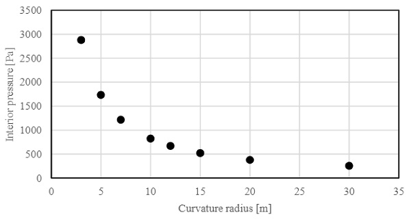
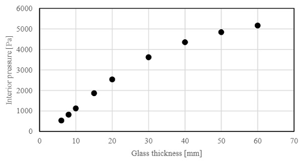
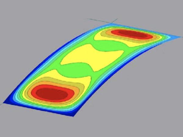
As extensively defined in the literature, the stiffer the glass panel, the higher the internal pressure due to climatic load. This relation is critical and has to be carefully considered during the design of cylindrical panels with small radius, Fig. 3. The influence of the glass thickness and the sealant silicone can be observed in Fig.4 and Fig.5 for this specific glass panel.
The internal pressure increases with the glass thickness, however the slope is lower for thicker laminate panels due to the influence of the silicone stiffness in the volumetric variation. The sealant silicone stiffness is relevant for bite between 10-30mm, but then, the influence of the panels volumetric stiffness govern the climatic performance.
6. Conclusion
A simulation tool for assisting the design and verification of flat and cylindrical insulated glass units (IGUs) is developed with the programmable COM Interface for the RFEM of Dlubal. The tool is validated comparing the results with SJ-MEPLA5.0.7 for flat panels and ANSYS Workbench 19.0 for flat and cylindrical panels. ANSYS simulation is carried out with a hydrostatic element which allows for accurate results for flat, curved and free-forms panels. The tool developed reduces drastically the pre-process and calculation time allowing for quick design decisions, parametric studies and accurate simulations even with multiple geometries and compositions.
7. References
Bao, M., Gregson, S.: Sensitivity study on climate induced internal pressure within cylindrical curved IGUs. Glass Struct.Eng. Vol. 4. No. 1. p. 29-44 (2019)
DIN 18008-1:2010-12. Glass in Building –Design and construction rules –part 1: Terms and general bases (2010)
DIN 18008-2:2010-12. Glass in Building –Design and construction rules –part 2: Linearly supported glazings (2010)
Feldmeier, F.: Insulating Units Exposed to Wind and Weather –Load Sharing and Internal Loads. Glass Processing Days. 8th edition. p. 633-636 (2003)
Marinov, V., Griffith, J.: Optimization of Curved Insulated Glass. Glass Performance Days. 10th edition. p. 67-70 (2015)
prEN 16612. Glass in Building –Determination of the load resistance of glass panes by calculation and testing (2013)