First presented at GPD 2019
Not only referring to unreached heights for the world’s tallest building, but also referring to new and unique landmark designs where architects and clients pushed the building industry to develop new, advanced and challenging technologies.
One of the current key trends is the request for so called complex geometry façades featuring curved, twisted or even free-form shape façades. These designs often require an early involvement of the façade specialist and the use of advanced computer aided design technologies incl. parametric modelling with script based graphical algorithm editors.
The output of these numerical and graphical computational design processes is used to evaluate the needs for curved or warped façade elements. Referring to warped glass and utilizing the cold-bending technology, being significantly more cost effective compared to the traditional hot-bent glass using slump forms, the two options single corner cold-bending and the free form cold-bending are compared and evaluated on two Middle East projects: The first example is the Shining Towers in Abu Dhabi, conceived as a pair of dancers moving together without touching.
The second example is The Opus project in Dubai where the unique appearance of the project was derived from an unusual source of inspiration as the architect sank a hot poker into a cube of ice to create the shape of the irregular, curved void façade.
Introduction
The glass cold-bending became an established technology in the façade industry used as an alternative to the costly slump form hot Options for Complex Geometry Façades - Single Corner vs. Free Form Cold-Bending bending of glass.
While the structural glass design of cold bent glass panels is relatively straightforward, the setting up of the cold bending limits (warp), the design of the primary seal structural silicone (between aluminium frame and glass) and the secondary seal (edge seal between inner and outer pane of the IGU) still presents a major challenge.
This paper focusses on the single corner cold-bending and the recently developed free form cold-bending, giving systematic overviews on the cold bending processes and structural silicone design. Project examples highlighting the two options include the Shining Towers in Abu Dhabi, and The Opus in Business Bay, Dubai.
The later represents one of the first façades being built using the new free form cold-bending process in a large scale. An additional item covered in this paper is the comparison and choice of appropriate IGU (insulating glass unit) spacer bars being able to withstand the high shear stresses caused by the cold-bending.
Cold Bending Options: Single Corner Cold-Bending vs. Free Form ColdBending
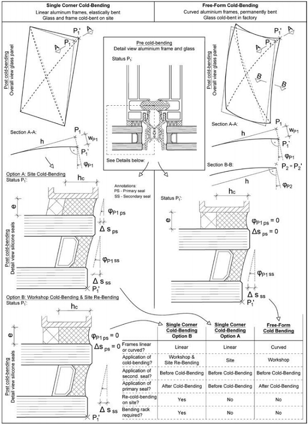
Figure 01 provides an overview of the two cold-bending options currently used in façade engineering projects. The single corner cold-bending is the most common option being realised on various projects over the last approximately 10 years. Various paper covered the principle technology and design methods, see [2], [3], [4] and [5].
Here the aluminium framing members are linear, and the glass is produced flat. For the free form cold-bending geometries including spherical convex, spherical concave, anticlastic freeform, convex free-form and concave / convex free-form, the glass is produced flat and the framing members are curved.
Referring to the cold bending distance ‘warp’, the single corner cold-bending only has one warp at one corner – three points define a coplanar surface and therefore only one corner point is warped (point P1, P3, P5 or P7). The edge warp (wp2, wp4, wp6 or wp8) of the two sides adjacent to the warped corner point can be assumed to be approximately half of the corner warp (P1, P3, P5 and P7).
For the free form cold-bending, the relation between corner warp and edge warp is more complex. While the corner warp P1, P3, P5 and P7 is usually a positive or negative value depending on a convex or concave coldbending, the edge warp values wp2, wp4, wp6 or wp8 are smaller in absolute values and could be as low as zero.
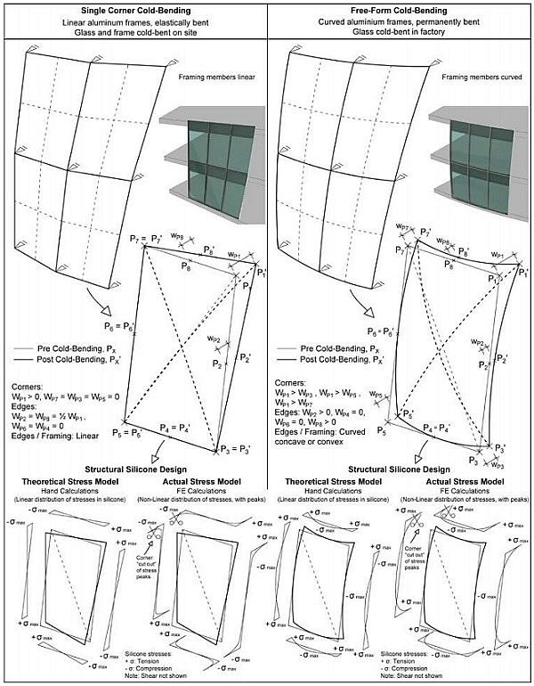
Referring to the structural silicone design of cold-bent glass and due to the glass trying to bend back into its original flat position, the elastic cold-bending process causes permanent (long term) tensile stresses in the primary and secondary silicone edge seals. The distribution of the permanent silicone tensile stresses depends on the cold-bending geometry and the method of stress analysis: hand calculations or Finite Element (FE) analysis.
Referring to the output of computational FE analysis and stress peaks encountered in the results graphs, the evaluation requires substantial expertise and engineering judgement.
The stress peaks are often localized in small areas and might be ‘cut-out’ to avoid an overly conservative design - considering that these small overstressed areas will result in a localised higher elongation, which shall be no problem for the overall system.
The concept of corner ‘cut-out’ of local stress peaks was presented for single corner cold-bending in [2] and further guidance on the durability of the edge seals can be found in [5].
Figure 01 compares the theoretical stress models (e.g. by hand calculations) with actual stress models (FE calculations), both for single corner cold-bending and free form shape cold-bending.
Single Corner Cold-Bending - Shining Towers, Abu Dhabi
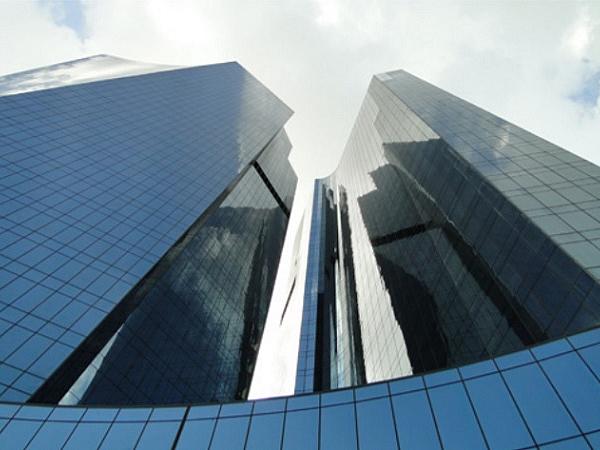
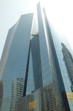
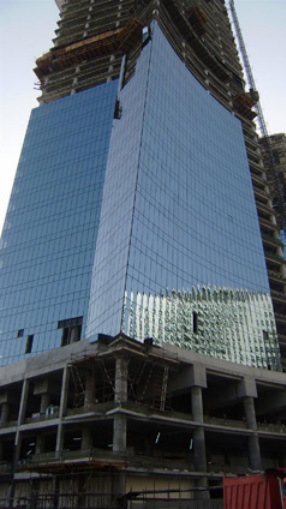
Conceived as a pair of dancers moving together without touching, the Shining Towers project in Abu Dhabi (see Figure 02 and 03) compromises two multi-storey towers (33 and 42 storeys respectively) that appear to ‘lean’ in two directions, sideways and towers one another.

Ramboll was appointed to provide multi-disciplinary services incl. façade engineering.
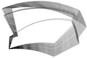
The office tower is a leaning and twisting building standing 34 storeys above the podium, Figure 04 shows the floor slab edges in plan twisting floor by floor over the building’s height.
The unique curving façade provided a challenge to the design team. Through intensive research and development at early stage of the project, followed by third-party testing, the team decided to proceed with double curved cold-bent façades.
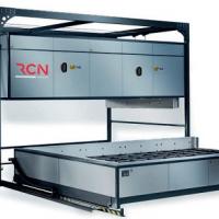
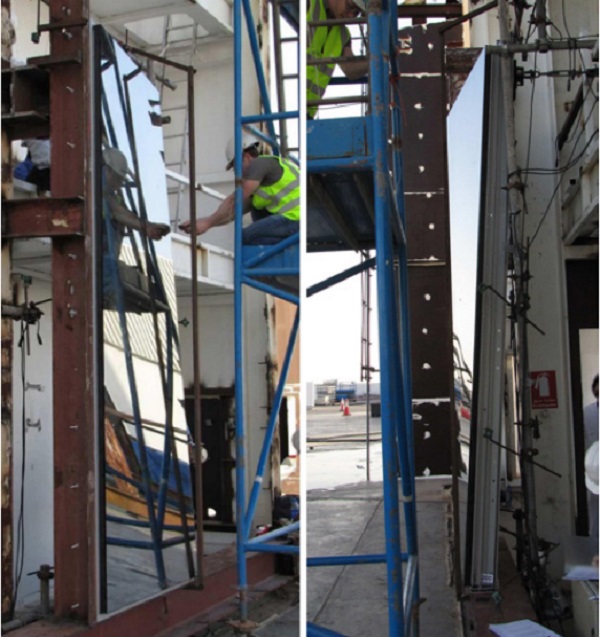
The façade system utilized the extrusions of a typical unitized façade flat system which is bent postproduction on site (see Figure 05) to follow the inclined and twisted façade. Also see Figure 13, Option A: Site cold-bending, post cold-bending. This solution eliminated the need for costly hot-bent curved glass, or an architectural re-design.
During the initial design stages, the question following questions came up:
- How to pull the unitized façade panel and what is the force?
- Won’t the glass break due to the coldbending?
- Won’t the structural silicone tear?
- Won’t the stack joint of the bent unitized panel be impossible to interface with adjacent panels?
Three phases were set up to achieve the required confidence the cold-bent design;
- Phase 1: Model verification
- Phase 2: Design verification
- Phase 3: Durability verification
For phase 1, actual units of the unitized façade were produced following the established model with actual aluminium extrusions, glass and details.
A certain number of these units were installed on initial resting rigs (see Figure 06) as per site conditions, then one corner pulled up to the maximum design cold bending ‘warp’ and further up to glass failure.
Details of this testing can be found in the next chapter. The goal of the testing was the verification of the theoretical assumptions to actual test results.
Single Corner Cold-Bending - Shining Towers, Cold-Bending Testing Mock-Up
Intensive mock-up cold-bending testing (see Figure 06) was carried out to determine and verify the accuracy of the structural calculations for the façade system and structural silicone. Measurements included glass stresses for the 30mm thick IGU with 8mm outer and 6mm inner pane in accordance with ASTM E998-05.
These stresses were derived by using tri-axial strain gauges to measure change in strain and subsequent the stresses in the glass during bending. The structural silicone dimensional changes were measured using digital callipers. For the coldbending test, a turn-buckle loading mechanism was attached to one corner of the unitized façade panel at bracket location through a load cell.
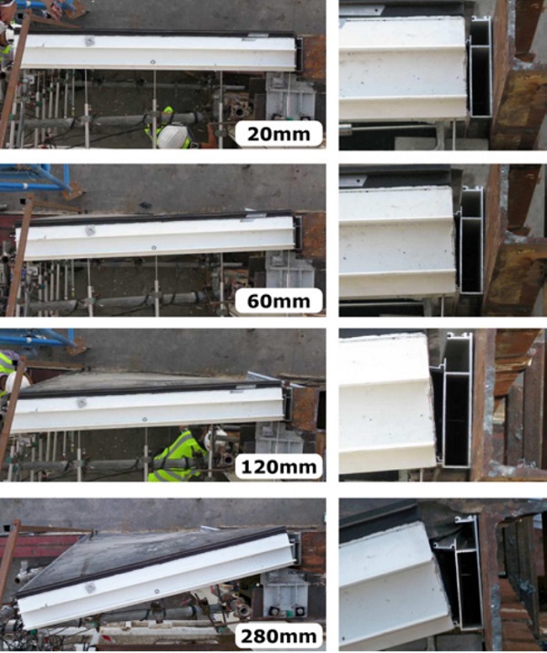
A rigid steel line was installed in parallel to the external glass surface as a reference. Digital callipers (LVDT transducers) were used to measure the dimensional changes, the results from all electronic instruments were recorded by computer controlled data logger. Initial bending ‘warp’ was applied at the top corner and then incrementally increased in 5mm steps (see Figure 07 and Figure 08) up to glass failure.
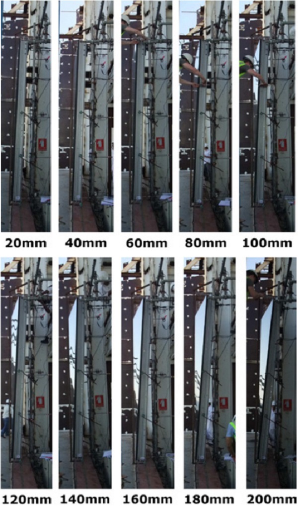
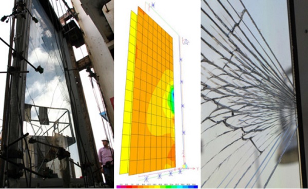
Figure 09 shows the crack origin at centre of the glass edge opposite to the cold-bend ‘warped’ corner, exactly matching the initial FE calculations. The deflections of the framing members, glass surface strain and sealant dimensions were measured at each bending increment. The initial bending was kept under loading for 48 hours and silicone strains were checked.
Free Form Cold-Bending – The Opus, Dubai
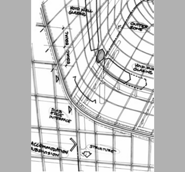
The most well-known project example of the new free form cold-bending technology is the Opus project in Dubai (Figure 10). The appearance of the building derives from the architect, world famous Zaha Hadid, sinking a hot poker into a cube of ice to create an irregular, curved void in the middle. Ramboll Façade was appointed for the initial design stages and set up the principle façade types and system approaches (see Figure 11).
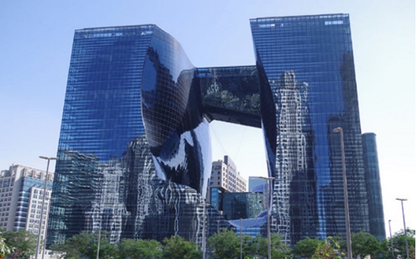
The project is mixed-use 20 story building with a hotel, serviced apartments and offices. The cube design is intended to float above the ground, featuring the above mentioned freeform void ‘hole’ in its centre to allow for eye-catching views. The sides of the void are formed by two concrete towers set approximately 50 m apart and linked above the void from the 20th floor upwards by a fivestorey steel bridge structure.
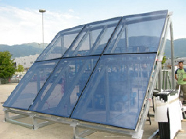
The external façades use relatively transparent glazing with a partial mirror pattern, in contrast to the freeform void area using dark blue glazing. Glass visual mock-up reviews and initial cold-bending testing was carried out a façade contractor’s factory, see Figure 12. The key feature free form void façade utilizes a combination hot bent glass, single corner cold-bent and free form cold-bent glass. Panel dimensions of the void façade are moderate with approximately 1.50 m x 1.95 m (nominal), 1.90 m x 2.20 m (widest) and 1.52 m x 2.51m (longest).
Due to its shape, the Opus void façade proved to be the most challenging part for the façade designer and contractor. The new technology of free form cold-bent glass was followed to reduce the quantity of hot bent glass and to achieve consequent cost savings.
Only for panels where the amount of warp and coldbending was above predefined limits and deemed excessive, partially spherical double curved hot bent glass was specified and produced using glass processing technology from the automotive industry.
The design of the primary and secondary structural silicone seals of the free form cold-bent panels was discussed in [1], including an explanation of the design approach ‘Engineering Stress’ vs. ‘Finite Element Stress’ and handling of stress peaks with ‘cutting-back’ as illustrated in Figure 01.
Different Types of Spacer Bars and Effect on the Shear Stresses due to Cold Bending
Figure 13 illustrates a typical IGU under coldbending deflections highlighting the critical shear stresses in the primary and secondary silicone seals. Detailed information on the design of the structural silicone for single corner cold-bending and free-form coldbending can be found in [1], [2], [3] and [6].
The illustrations in Figure 13 also show that the shear forces not only affect the primary and secondary seals, but also the IGU spacer bars. Traditionally, the spacer bars are aluminium or stainless steel hollow sections filled desiccant. Obviously, these relatively ‘stiff’ spacer bars have more issues to cope with high shear deflections compared to the recently developed ‘flexible’ spacer bars.
The ability of IGU edge seals and spacer bars to cope with high deflections is not only important for long term cold bending deflections, but also for short term deflections due to wind loads. These short term deflections are usually an issue for façade system with high deflections, e.g. cable façades being subject to relatively high short term edge warp deflections in the IGU’s. The theory behind edge warping of insulating glass units was described in detail in [1].
For both the edge warping deflections and the ‘normal’ mid-span deflection deflections, the edge seal as well as the spacer bar of insulating glass units are the governing factors for the deflection or (cold-bending) warp limit. Besides the traditional aluminium und stainless steel spacer bars, two relatively new types of spacer bars are available: A) Silicone foam spacers, and B) Thermo plastic spacers (TPS spacers).
TPS spacers usually consist of a one component polyisobutylene with included desiccant material. As there is no stiff metal insert (in contrast to aluminium or stainless steel spacers) and the whole spacer is made of a homogeneous, relatively flexible material, these spacers tend to be able to withstand higher deflections of the insulating glass units compared to metal spacer bars.
Figure 14 gives an overview of the different types of spacer bars. Referring to the aluminium and TPS spacer bars, several tests and numerical analysis carried out by the Institute for Lightweight Structures and Conceptual Design (ILEK, University of Stuttgart) were carried out as part of two diploma works, refer to [7] and [8]. These have picked up the problem of edge warping and mid-span deflections of insulating glass units.
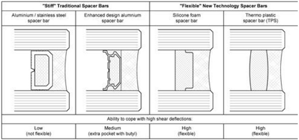
Figure 15 shows a typical comparison of aluminium and TPS spacers under deflections testing; the ‘flexible’ TPS spacer shows significant lower shear stresses while being able to withstand higher elongations – as a consequence to higher deflections of the insulating glass unit. The importance of the spacers and edge seals of insulating glass units is widely known, IGU processors are limiting the amount of stresses in the spacers and edge seals since many years by giving deflection limits for the insulating glass panel.
![Figure 15: Test results comparing ‘stiff’ aluminium spacers vs. ‘flexible’ TPS spacers [7], [8]](/sites/default/files/inline-images/Fig15_2.jpg)
These limits shall guarantee that the edge seals of the insulating glass unit do function over a long period of time, keeping in mind that a failure of the edge seals would lead to air and moisture penetration through the seal into the cavity of the insulating glass unit and condensation within the glass unit would occur. In case this happens, a replacement of the insulating glass unit would be required leading to high costs for access to the glass panels, dismounting and installation of the new IGU.
Summary
Following the architectural trend pushing for more and more complex façade geometries including two-way curvatures, the single corner cold-bending method represents a less common however over the recent years relatively well researched technology. The paper presents a landmark project in Abu Dhabi where this single corner cold-bending technology was successfully tested and realized.
A more novel and advanced approach for even more complex geometry façades is the free form cold-bent glass method, being implemented in a large scale for the first time on The Opus project in Dubai. For both the single corner cold-bending and free form coldbending approach, the effect of the glass trying to elastically deflect back into its original flat position must be considered.
Here, the primary and secondary seal structural silicones and the IGU spacer bars tend to be the weak point and careful design considerations are required as current design standards do not cover these topics. This paper intends to provide guidance including a systematic and in-depth review of the associated issues.
Acknowledgements
[1] Beer, B.: Free-Form Shape Cold-Bent Structural Silicone Glazed Façades - Design Concept and Challenges, Glass Performance Days, 2017
[2] Beer, B.: Structural Silicone Sealed Cold-Bent Glass – High-Rise Projects Experience Leading to a New Design Concept, Glass Performance Days, 2015
[3] Beer, B.: Complex Geometry Façades – Introducing a New Design Concept for Cold-Bent Glass, Glass Performance Days, 2013
[4] Datsiou, K.C., Overend, M.: The mechanical response of cold bent monolithic glass plates during the bending process, Engineering Structures 117 (2016) 575-590, 2016
[5] Besserud, K.,Bergers, M., J. Black, A., Donald, L. D., Mazurek, A., Misson, D., Rubis, K.: Durability of Cold-Bent Insulating-Glass Units, Journal of ASTM International, Vol.9, No.3, 2012
[6] Dow Technical Information (Ver 1.01, 14.03.2019) version 29/06/2018, Cold Bent Glass in Structural Glazing, Dow Chemical Company
[7] Fauth J., Flexibilität des Randverbunds von Isolierglasscheiben, Diplomarbeit, Institut für Leichtbau Entwerfen und Konstruieren, Universität Stuttgart, 2004
[8] Yang H., Untersuchung zur Bestimmung der mechanischen Eigenschaften von Randverbundsystemen von Isolierglasscheiben, Diplomarbeit, Institut für Leichtbau Entwerfen und Konstruieren, Universität Stuttgart, 2006.