By Misael Rojas, RRO, AIA, NCARB
IIBEC Interface Journal - March/April 2026
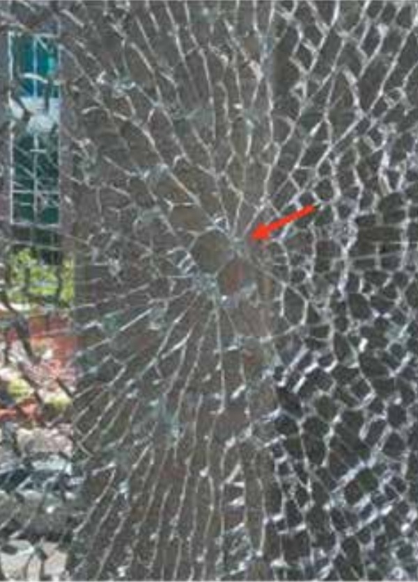
NICKEL SULFIDE (NIS) inclusions represent a persistent and significant challenge within the domain of architectural glazing, particularly concerning thermally toughened (tempered) glass employed in window and curtainwall assemblies. These microscopic impurities, inadvertently introduced during the glass manufacturing process, constitute a primary etiology of spontaneous glass breakage. The fundamental mechanism involves a protracted, time-dependent phase transformation within the NiS inclusion, culminating in a volumetric expansion of the contaminating debris ranging from 2.5% to 4% in size.1 This expansion generates substantial localized stress within the glass’s central tensile zone, initiating crack propagation and ultimately precipitating the sudden and frequently delayed disintegration of the pane, which may occur years after installation. The characteristic “butterfly pattern” (Fig. 1) observed at the fracture origin serves as a definitive diagnostic indicator of NiS-induced failure of the glass.
While NiS inclusions are rare, occurring in roughly 1 out of every 1,100 tonnes (1,200 tons) of raw glass,²’³ they pose a disproportionately high risk. These microscopic imperfections can lead to spontaneous glass breakage, a significant concern, especially in highly visible, high-traffic, or overhead installations like curtainwalls. The unpredictable timing of these failures—which can happen years or even decades after installation—magnifies the perceived danger, making robust mitigation strategies essential for public safety and structural integrity.
A fundamental impediment to addressing NiS inclusions stems from their inherent invisibility and undetectability in intact glass. This limitation elucidates why some manufacturers typically refrain from offering warranties specifically against NiS-induced breakage. Consequently, post-production, destructive testing, exemplified by heat soak testing (HST), has emerged as the predominant industry-accepted solution for risk management. HST accelerates the phase transformation under controlled environmental conditions, thereby inducing the breakage of defective panes prior to installation. Laminated glass offers an additional stratum of safety by retaining glass fragments after breakage, even in instances of an NiS-induced fracture, thereby mitigating the risk of falling debris. Glass manufacturers are also implementing stringent protocols within their facilities to ensure the components that contribute to contamination of the batch of glass are held to a minimum.
UNDERSTANDING NIS INCLUSIONS IN GLASS
Definition and Characteristics
NiS inclusions are minute crystalline particles composed of nickel and sulfur (Table 1), which form unintentionally as impurities during the float glass manufacturing process. These particles are intrinsically distinct from the surrounding glass matrix. Visually, they typically present as small, dark-colored specks or opaque solids embedded within the glass (Fig. 2). Upon recovery from a fracture origin, they may exhibit a golden-yellow hue.
TABLE 1. Characteristics of nickel sulfide inclusions Property Description/range
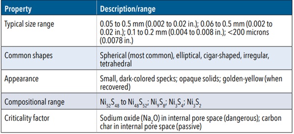
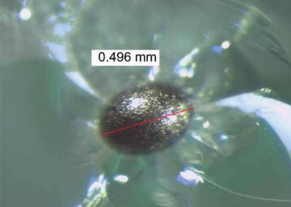
The dimensions of these inclusions generally range from barely perceptible (approximately 0.05 mm [0.002 in.]) up to 0.5 mm (0.02 in.) in diameter, with some observations reporting sizes between 0.06 and 0.5 mm (0.002 and 0.02 in.) or 0.1 and 0.2 mm (0.004 and 0.008 in.). While frequently spherical, their morphology can also encompass elliptical, cigar-shaped, irregular, or even tetrahedral forms (Fig. 3), indicative of their existence as molten droplets within the glass melt prior to crystallization during cooling. These inclusions often have uneven surfaces, resembling a golf ball, which further substantiates their crystallization process, as the formation of a crystallized object often portrays a textured surface.
From a compositional standpoint, NiS inclusions typically fall within the stoichiometric range of Ni₅₂S₄₈ to Ni₄₈S₅₂, meaning that the ratios required to create the anomaly are dependent on one another. Inclusions exhibiting a nickel-rich stoichiometry are frequently observed as two-phase assemblies, whereas those on the sulfur-rich side of stoichiometric NiS generally present as single-phase. A critical finding in the characterization of NiS inclusions involves the differentiation between “classic” (hazardous) and “atypical” (inert) types. This distinction is not primarily predicated upon their overall chemical composition but rather upon the material residing within their internal pore space. Hazardous inclusions are characterized by the presence of sodium oxide (Na₂O), whereas inert ones contain carbon char (primarily carbon [C], with varying amounts of hydrogen [H], oxygen [O], and trace amounts of nitrogen [N] and sulfur [S]). This compositional nuance underscores that not all NiS inclusions pose an equivalent threat, indicating the need for a more intricate understanding of their potential for inducing fracture.
Origin and Formation Mechanisms
The presence of nickel and sulfur, the constituent elements of NiS inclusions, can be traced to various sources within the glass manufacturing process. The primary source of nickel is typically identified as impurities within the raw materials such as sand, soda ash, and limestone, or contamination originating from stainless steel equipment utilized in the float process.4 This encompasses feeders, storage and handling apparatus, furnace structures, and even weld slag. Although nickel oxide (NiO) is occasionally employed as a colorant in certain glazings, the prevailing industry understanding suggests that its introduction in oxide form does not typically lead to NiS inclusions, as it is not introduced in metallic form. Contamination could originate from sources as simple as a misplaced soda can or metallic object from any of the workers or staff of the factory.
Sulfur primarily originates from fining agents—such as sodium sulfate (Na₂SO₄)— which are commonly utilized in the float process to eliminate bubbles and enhance glass clarity. It can also be introduced through furnace fuels; for instance, oil may potentially contain up to 3 parts per million (ppm) of NiO. Even seemingly insignificant quantities, such as 3 ppm of NiO, possess the potential to result in widespread NiS inclusions throughout the float process.
The formation of NiS inclusions generally proceeds through three distinct stages. First, nickel separates from other metals within an alloy, a process governed by Ostwald’s step theory,⁵ which is influenced by the nobility of the metals. Second, nickel bonds with sulfur to form NiS via chemical equilibria. Illustrative reactions include 4Ni₂ + SO₃ → NiS + 3NiO, or the more intricate interaction of nickel-iron (Ni-Fe) alloys with sodium sulfate: NiFe₃ + Na₂SO₄ → Na₂Oglass + 3FeOglass+ NiS. Finally, the newly formed NiS particles become entrapped within the glass as it undergoes cooling. Specific production procedures, particularly rapid cooling rates during glass manufacturing, can further contribute to an increased frequency of NiS precipitation.
Despite continuous industry endeavors to enhance raw material purity and implement stringent manufacturing controls, NiS contamination remains an inherent and persistent challenge. The difficulty in achieving complete elimination is underscored by the fact that even a minute quantity—specifically, 1 g (0.04 oz) of nickel that has reacted with sulfur to form NiS—possesses the potential to contaminate the float process for a duration of up to 10 days, corresponding to approximately 6,000 tonnes (6,600 tons) of glass, and generate up to 1,000 inclusions of 0.15 mm (0.006 in.) diameter.⁶ This extreme sensitivity to minute contaminants highlights a fundamental manufacturing challenge: NiS constitutes a systemic risk that necessitates management rather than complete eradication at the source. Despite the stringent quality control (QC) measures that glass manufacturers have implemented, the industry’s inability to fully prevent the formation of these microscopic impurities mandates robust post-production risk management strategies.
The Spontaneous Breakage Phenomenon: The Alpha-Beta Phase Transformation of NiS
The spontaneous breakage of tempered glass attributable to NiS inclusions is fundamentally driven by a crystallographic phase transformation occurring within the inclusion itself.⁶ NiS is a complex material that undergoes a change in its crystalline structure, known as a phase change, at a transformation temperature typically ranging between 282°C (539.6°F) and 379°C (714.2°F). The precise temperature at which this transformation occurs is contingent upon the exact stoichiometry, or the specific elemental proportions of nickel and sulfur, within the inclusion.
At elevated temperatures, such as those experienced during the glass tempering process (approximately 620°C [1,148°F]), NiS converts to its alpha (α) phase. This α-phase represents the high-temperature stable form and occupies a smaller volume. However, during the subsequent rapid cooling (quenching) stage of tempering, the glass rapidly solidifies. This expedited cooling precludes the NiS inclusion from having sufficient time to revert to its low-temperature stable beta (β) phase. Consequently, the NiS inclusion becomes effectively “frozen” within the solid glass in its unstable, high-temperature α-phase (Fig. 4).
Over an extended duration, the entrapped α-phase slowly and progressively converts back to the β-phase, which is the stable form at ambient temperatures. This phase conversion is accompanied by a significant volumetric increase, typically ranging from 2.55% to 4%. This delayed transformation operates as a delayed controlled explosion within the glass. The defect is introduced during the manufacturing process, yet its manifestation is deferred, rendering spontaneous breakage an unpredictable and long-term issue that may occur years subsequent to installation.
Interaction with Tempered Glass: Stress Generation and Fracture Mechanics
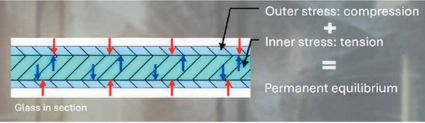
Tempered glass is specifically engineered to possess a permanent equilibrium of internal stresses, characterized by a highly compressed outer surface and a central core subjected to significant tensile stress. This internal tension of the glass can reach at least 69 MPa (10,000 psi).
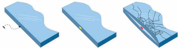
Should an NiS inclusion be of sufficient size and, critically, situated within this central tensile stress zone (which typically constitutes the inner 60% of the glass thickness) (Fig. 5), the volumetric expansion resulting from its α-β phase transformation (Fig. 6), can exert immense localized pressure upon the surrounding glass matrix. Hydrostatic stress at the inclusion/glass interface has been estimated to attain values from 835 MPa to 920 MPa (approximately 121,110 psi to 133,440 psi).⁷
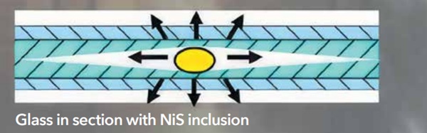
This extreme localized stress is frequently sufficient to nucleate microscopic cracks, sometimes referred to as vents, at the interface between the glass and the inclusion. Once initiated, these microcracks propagate rapidly due to the high stress concentrations at their tips, ultimately leading to the sudden, often explosive, disintegration of the entire glass pane. Numerical simulations, which model the volume change of NiS inclusions using an analogy between temperature and phase expansion, corroborate these observations. These simulations demonstrate that even relatively small inclusions possess the capacity to generate maximum stresses far exceeding the intrinsic strength of the glass, thereby leading to destructive failure even with only partial (for example, 20%) phase transformation of the inclusion.
IDENTIFYING NIS BREAKAGE: THE BUTTERFLY PATTERN AND OTHER INDICATORS
Spontaneous breakage attributed to NiS inclusions exhibits a highly distinctive and recognizable fracture pattern, which is crucial for forensic analysis. This pattern typically originates from a singular point within the glass and radiates outward in a symmetrical formation, frequently described as a butterfly, figure eight, or cat’s eye. At the precise focus of the break, observers will likely discern a pair of polygons bordering one another. If these polygons are nearly identical in size, it strongly suggests an NiS inclusion as the causative factor.
The NiS inclusion itself, a minute speck often measuring between 0.1 and 0.2 mm (0.004 and 0.008 in.) (Fig. 3), can frequently be located at the border between these two polygons. It may be discernible under moderate magnification or, for definitive identification, via electron microscopy. A key distinguishing characteristic of NiS-induced breakage, differentiating it from external impact damage, is the absence of any apparent localized crushing or other indications of impact at the fracture origin. This lack of external force confirms the internal genesis of the failure.
Factors Influencing Breakage Probability and Time-to-Failure
The time-to-fracture for glass containing NiS inclusions is notably unpredictable. Breakage can occur anywhere from weeks to months, or even many years, subsequent to the manufacturing of the glass or installation.
While instances of failure have been observed after more than 20 years, such occurrences are exceptional, with breakdowns seldom manifesting more than 10 years after installation. Statistical data indicate that approximately 90% of NiS-induced breakages typically occur within a period of 6 to 8 years following production, even in cold climates.
Numerous factors contribute to the variability in time-to-fracture. These include the size and purity of the NiS inclusion, its precise location within the tensile zone of the tempered glass (Fig. 5 and 6), and the temperature cycling the glass experiences in its operational environment. For example, window glass installed in the Northern Hemisphere sometimes exhibits earlier failures on the south-facing side, which is attributed to greater solar exposure and associated thermal fluctuations. This, however, does not equate to a typical pattern, as historic examples—one of which is discussed in this article—have been observed with conditions that do not always comply with this finding.
Estimated failure rates attributable to NiS inclusions vary widely across different sources and conditions, reflecting the inherent complexity and variability of the problem. A general estimate for the occurrence of NiS inclusions is approximately one inclusion per 8 tonnes (9 tons) of raw glass. For tempered glass, estimates of breakage range from one inclusion breakage per 450 tonnes (500 tons) to one per 4 tonnes (5 tons). In specific building contexts, a failure rate of 1.73% over a 12-year period has been observed among 17,760 panels. For heat-strengthened (HS) glass, a breakage probability of 1 in 1,100 ± 200 tonnes (1,200 ± 220 tons) can be estimated. These varying statistics underscore that NiS-induced failures frequently manifest in batches of glass, suggesting a correlation with specific raw material loads or variations in QC at particular float glass plants.
While the inherent stress in tempered glass constitutes a necessary condition for NiS-induced breakage, the architectural application, specifically in high-rise buildings and curtainwalls, significantly elevates the risk from a material science curiosity to a critical public safety and liability concern. The sheer volume of glass utilized in such structures, combined with the height of installation and the potential for falling fragments, transforms a statistically rare event into a high-impact hazard. This necessitates specialized mitigation strategies that extend beyond standard glass specifications, emphasizing the importance of addressing the potential consequences of even low-probability events in high-risk environments.
NIS INCLUSIONS COMPARED WITH OTHER TYPES OF DAMAGE: UNDERSTANDING THE DIFFERENCES
Glass failures can be complex, and distinguishing between NiS inclusions, edge damage-related breakage, and thermal stress breakage is essential for accurate forensic investigations. While both can lead to spontaneous glass failure, their causes and failure mechanisms are distinct.
Edge Damage, the Impact of Hard Setting Blocks, and Improper Placement on Glass Integrity
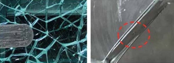
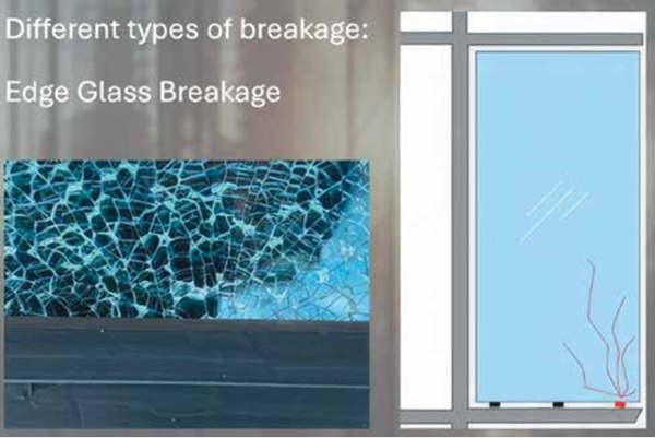
Setting blocks, typically made of neoprene, ethylene propylene diene terpolymer, or other elastomeric materials, provide cushioning and load distribution for glass units. When overly rigid or improperly placed, they create localized stress points at the glass edge, creating what is known as glass edge damage. This leads to microfractures that propagate over time, edge chips due to concentrated pressure, and increased vulnerability to thermal and mechanical loads, accelerating failure (Fig. 7). This is one of the main defects often confused with NiS breakage. Unlike NiS inclusions, edge damage is typically introduced during handling, transportation, or improper installation. Hard setting blocks and incorrect glass placement can exert excessive localized pressure, causing small fractures that propagate under environmental and mechanical stress. These edge defects become stress concentrators, weakening the glass and increasing the risk of spontaneous failure under relatively normal conditions (Fig. 8).
Glass edge integrity is critical for long-term performance, especially in structural glazing and curtainwall systems. Improper placement causes the following:
- Misalignment, where the glass is not seated correctly, leading to uneven pressure distribution.
- Binding issues, restricting thermal expansion and contraction, causing stress-induced cracking.
- Excessive contact with frame components, leading to abrasion and eventual spontaneous breakage.
- Failure may occur due to thermal expansion, wind loads, or impact.
Consequences of poor installation practices include the following:
- Spontaneous failure—glass breakage due to accumulated stress.
- Reduced impact resistance, increasing susceptibility to external forces.
- Compromised weatherproofing, affecting performance in building enclosures.
The following are common indicators of edge damage failure:
- Damage originating at the edge or corners.
- Visible chips or cracks along the perimeter.
- Breakage pattern might show larger fragments and radiating fractures.
Misdiagnosis and Its Impact
Because both NiS inclusions and edge damage can result in unexplained breakage, misidentification can lead to incorrect conclusions about liability and corrective actions.
- NiS-related failures often necessitate manufacturer intervention, highlighting QC issues.
- Edge damage failures, on the other hand, point to handling or installation errors, requiring stricter protocols for glass placement and support systems.
Proper forensic examination, including fractography analysis and breakage pattern assessment, is crucial to distinguish both the differentiation between glass edge damage and NiS inclusion damage as well as the causes of the edge damage to implement the right mitigation measures.
Thermal-Stress-Related Damage
Due to solar exposure, uneven heating creates pronounced thermal gradients in the glass, causing parts of it to expand while others remain cool. This differential expansion generates tensile “hoop stresses,” especially near the glass edges, where even minor preexisting imperfections can trigger crack initiation. The use of rigid ceramic frit coatings—which absorb more infrared energy and do not flex with the underlying glass—further exacerbates these stresses, leading to fracture propagation once a crack initiates.
Testing and analysis, including fractographic studies and finite difference thermal modeling, typically can confirm that while HS glass meets ASTM surface compression standards,⁸ the combined environmental and design factors may still induce stress levels exceeding the material’s tensile limits. Key findings include the following:
- Thermal gradients: resulting in high tensile or compressive edge stress on the inboard pane.
- Edge vulnerabilities: where slight defects can serve as focal points for crack initiation.
- Impact of ceramic frit: rigid coatings (especially red frits) amplify thermal stresses due to poor elasticity.
Brief recommendations include considering alternative glass types, adopting less aggressive coating strategies, and improving behind-the-glass ventilation to mitigate thermal differentials and reduce future breakage risks.
UNDERSTANDING NIS INCLUSIONS: FORMATION AND RISKS
NiS is not an intended component of glass but rather a contaminant that forms when nickel and sulfur react during the glass manufacturing process.¹ Understanding the origins and behavior of these inclusions is fundamental to developing effective mitigation strategies.
Primary Sources of Nickel Contamination
Nickel contamination can originate from several points within the glass production life cycle:
- Raw material impurities: Nickel-bearing minerals can be present as impurities in primary raw materials such as silica sand, soda ash, or recycled glass (cullet). High-purity silica sand, for instance, is critical to prevent defects like inclusions.
- Production equipment wear: Components within the manufacturing line can shed nickel-containing particles. This includes nichrome wire from heating elements, stainless steel particles from conveyor systems and cutting tools, and welding spatter resulting from furnace maintenance.
- Environmental contamination: Nickel-containing dust from industrial operations within the factory environment and combustion residues from furnace fuels can also introduce nickel into the molten glass.
Industry Standards and Quality Management Systems for Glass Production
Glass manufacturers operate within a framework of international and national standards that define quality, safety, and performance criteria. While no single standard directly quantifies acceptable NiS inclusion limits, these overarching guidelines provide the foundation for quality management and defect control.
The glass industry is governed by both US and international standards, including those from the International Organization for Standardization,9 ASTM International,8 and the European Standards (EN).10 These standards serve as crucial pillars, ensuring the consistent quality, safety, and regulatory compliance of glass products across diverse applications. They provide comprehensive specifications for a multitude of characteristics, from permissible defects and controlled fragmentation patterns to robust quality management systems, ultimately fostering trust among consumers and stakeholders while addressing those factors.
However, a critical void persists within this otherwise well-regulated landscape, particularly concerning NiS inclusions. Despite the potential for these microscopic imperfections to cause delayed breakage in tempered glass, there remains a significant gap in universal standards.¹¹ Specifically, there are no established, globally recognized standards that do the following:
- Explicitly mandate the detection of NiS in raw glass materials: This proactive approach could prevent contaminated glass from even entering the manufacturing process.
- Define precise numerical limits for NiS inclusions: Without quantifiable thresholds, manufacturers lack clear benchmarks for acceptable levels of NiS.
- Stipulate the use of specific, validated detection technologies: The absence of mandated technologies allows for variability in detection methods, potentially leading to inconsistent results.
While general industry standards do address a broad spectrum of blemishes and imperfections in glass, the specific control and mitigation of NiS inclusions largely fall back on individual manufacturers’ internal quality assurance (QA) and QC processes. This reliance on proprietary methods means that the rigor and effectiveness of NiS detection and prevention can vary significantly from one manufacturer to another.
Post-tempering mitigation strategies, such as heat soaking, are commonly employed to address the risk of NiS-induced breakage. This process, while effective in reducing the risk of spontaneous breakage in the field, is a reactive measure rather than a proactive one focused on preventing NiS from entering the product stream in the first place.
t is noteworthy that ASTM standards, while widely recognized and utilized, are often considered a “baseline” or “minimum requirement” within the glass industry.6 This perception drives many manufacturers to go above and beyond these foundational specifications. By implementing their own rigorous and often proprietary QA/QC practices, these manufacturers aim to achieve superior quality levels that exceed the minimum acceptable standards. This proactive approach is particularly vital in addressing the persistent and complex challenges posed by NiS inclusions, as it reflects a commitment to delivering glass products with enhanced reliability and safety, ultimately safeguarding their reputation and consumer confidence. The absence of specific NiS standards thus highlights an area where industry-wide collaboration and the development of new, comprehensive guidelines could significantly enhance the safety and performance of tempered glass.
PREVENTION AND MITIGATION STRATEGIES
Given the inherent challenges in completely eliminating NiS inclusions from glass manufacturing, the industry has focused on both pre- and post-production prevention and mitigation strategies to reduce the risk of spontaneous breakage in installed glass.⁶
Proactive Measures: Raw Material Sourcing and Furnace Environment Control
Minimizing NiS contamination should begin long before the glass is formed, with stringent controls at the earliest stages of the manufacturing process. Glass manufacturers are adopting advanced production technologies and QC systems designed to detect and eliminate nickel contaminants from the earliest stages of the process.
Use of higher-purity raw material. The quality of raw materials directly impacts the final product’s quality. Manufacturers prioritize high-purity sourcing of primary components such as silica sand, soda ash, and limestone, ensuring minimal trace elements of nickel and sulfur. Rigorous inspection and testing procedures are implemented for incoming raw materials, including comprehensive chemical analysis, particle size distribution analysis, and physical property testing, to ensure they meet strict criteria for purity and consistency. Any deviation from specified standards can be promptly addressed to maintain the integrity of the manufacturing process. Collaboration with certified, reputable suppliers who uphold rigorous quality standards is essential to ensure the purity of incoming materials.
Advanced cullet management. Cullet is a known and significant source of nickel contamination. To mitigate this, manufacturers implement advanced cullet management strategies, including meticulous monitoring of cullet moisture, granulometry (particle size distribution), and contamination levels. Automated magnetic separation systems are employed to effectively remove nickel-rich fragments, such as stainless steel, nichrome wire, and welding debris, particularly from cullet streams. Furthermore, closed-loop material handling systems are designed to segregate raw materials from recycled glass, minimizing the risk of cross-contamination.
Minimizing contamination from furnace components. Production equipment wear, including nichrome wire from heating elements, stainless steel particles from conveyor systems and cutting tools, and welding spatter from furnace maintenance, is a recognized source of nickel contamination. To counteract this, manufacturers are increasingly adopting nickel-resistant or nickel-free furnace components, such as ceramic wear plates, coated linings, and non-nickel alloys, to limit direct contact-based contamination within the furnace. Automated cleaning systems, featuring high-efficiency vacuum and filtration, are deployed to remove nickel-laden dust from critical areas of the production environment. The selection of refractory materials for furnace linings is also critical; these materials are chosen for their high stability, thermal shock resistance, chemical stability, and inherent resistance to contamination of the molten glass.
Real-time monitoring during melting. Advanced screening, like X-ray fluorescence (XRF)⁶'¹² and inductively coupled plasma (ICP) spectroscopy, detect nickel and metallic impurities before melting. Laser-induced breakdown spectroscopy (LIBS)² technology offers rapid, real-time detection of nickel compounds during melting for immediate adjustments, outperforming slower methods. Some plants also use electrified lances to attract molten metallic impurities.
The shift from reactive QA to proactive QA is evident in these measures. Traditionally, QA might have focused on inspecting finished products. However, the prevalence of “invisible” NiS inclusions and the understanding of their diverse origins have pushed manufacturers to adopt advanced production technologies and QC systems designed to detect and eliminate nickel contaminants from the earliest stages of the process. This includes using technologies like XRF, ICP, LIBS, and magnetic separation before melting. This signifies a strategic shift in QA/QC from merely identifying defects at the end of the line to actively preventing their formation from the very beginning. This proactive approach is essential for contaminants like NiS that are difficult to detect after production and whose effects are delayed. It also implies significant investment in up-front technology and supplier relationships.
The increasing automation and integration of advanced analytical tools, such as LIBS for real-time elemental analysis, are critical for managing microscopic impurities that human inspection cannot catch. This trend indicates that future improvements in NiS minimization will likely come from further technological advancements in process control and real-time detection, moving towards a “smart factory” model where contamination is identified and addressed instantaneously via artificial intelligence and other adaptive technologies.
HST: The Primary Mitigation Method
HST represents the most widely adopted and efficacious post-production thermal treatment designed to mitigate the risk of spontaneous breakage in tempered glass caused by NiS inclusions. The primary objective of HST is to accelerate the α-β phase transformation of any critical NiS inclusions present, thereby inducing their breakage within a controlled environment (the heat soak oven) rather than subsequent to the glass’s installation in a building.
The HST process involves placing tempered glass panels in a calibrated oven and subjecting them to a controlled heating cycle. The glass surface is heated to a temperature typically ranging between 260°C (500°F) and 290°C (554°F) (for example, 280°C is specified by EN 14179-1, Glass in Building — Heat Soaked Thermally Toughened Soda Lime Silicate Safety Glass).10 This temperature is then maintained for a minimum dwell time, frequently 2 hours, followed by controlled cooling. During this process, the glass itself does not soften; however, the elevated temperature accelerates the volumetric expansion of any unstable NiS inclusions, causing defective panes to shatter within the oven.
HST significantly reduces the likelihood of spontaneous breakage in the field. Estimates suggest that heat soaking can eliminate approximately 95% of problematic windows, or reduce the risk from 1 m² in every 10,000 m² of glass to 1 m² in every 1 million m².¹³ Other statistical data indicate a reduction in breakage probability from 8 out of every 1,000 panels to 3 to 5 out of every 1,000 panels.
Despite its demonstrated effectiveness, HST is not entirely infallible, implying that it cannot guarantee the complete elimination of all NiS-related breakages. Furthermore, it is a destructive test, as affected panes are intentionally broken. Additionally, the process contributes to both the cost and lead time of glass production. European standards, such as EN 14179-1 (2005/2016),¹⁰ provide rigorous specifications for the heat soak process, encompassing temperature and dwell time requirements. While ASTM C1048, Standard Specification for Heat-Treated Flat Glass — Kind HS, Kind FT Coated and Uncoated Glass,⁸ serves as the industry standard for heat-treated flat glass in the US, a direct American standard specifically for HST currently does not exist. The reliability of HST is also influenced by factors such as precise oven temperature control, proper alignment of glass stacks, and adequate spacing between sheets during the testing to ensure homogeneous heating.
Laminated Glass as a Safety Measure
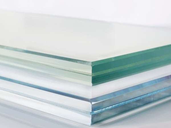
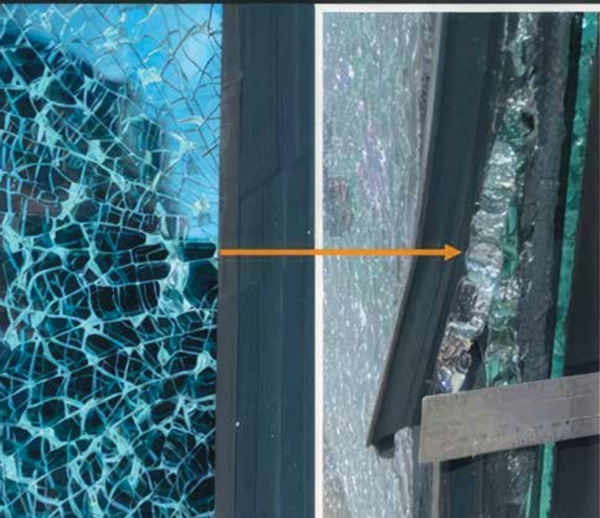
Laminated glass offers a critical safety measure in applications where spontaneous breakage, including that caused by NiS inclusions, is a concern. It is constructed by bonding two or more layers of glass with an interlayer, typically polyvinyl butyral or ionoplast (Fig. 9).
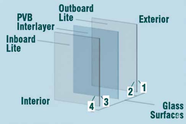
The primary advantage of laminated glass resides in its capacity to retain glass fragments upon breakage. Should a pane of laminated glass shatter, the interlayer securely holds the broken pieces together, thereby preventing their scattering and significantly reducing the risk of injury from falling glass, particularly in overhead applications or high-traffic areas. It is imperative to comprehend that laminated glass does not preclude NiS inclusions from inducing a fracture in one of its glass plies. Rather, it mitigates the consequences of such a fracture by preserving the integrity of the overall panel. This characteristic renders it a preferred choice for applications where safety is paramount, such as balustrades, facades, and automotive windshields.
Laminated glass can be specified with HS glass, which is not considered safety glass on its own due to its breakage pattern, to provide the necessary fragment retention for safety glazing requirements. However, laminated glass is not without its own potential issues, such as delamination, wherein the adhesive bond between the glass and the interlayer degrades. This phenomenon can be precipitated by excessive moisture, incompatible structural silicones, or roller wave distortion originating from the manufacturing process. Proper installation practices, including ensuring adequate ventilation at glass edges and utilizing compatible materials, are crucial to prevent delamination.
HS Glass
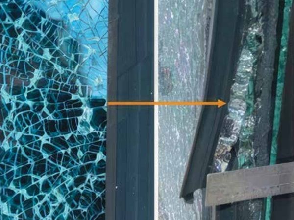
HS glass constitutes a type of heat-treated glass that undergoes a heating and cooling process, rendering it approximately twice as strong as annealed (standard) glass of equivalent thickness. The cooling process for HS glass is more gradual than that for fully tempered glass, resulting in lower surface compression (3,500 to 7,500 psi [24 to 52 MPa]).⁴
A key characteristic of HS glass is its breakage pattern: upon fracture, it breaks into larger, often sharp shards, similar to that of annealed glass. Unlike tempered glass, these fragments typically remain within the frame, yet they present a higher risk of piercing and cutting injuries (Fig. 10). Consequently, HS glass generally does not fulfill safety glazing requirements as delineated by standards such as ANSI Z97.1, American National Standard for Safety Glazing Materials Used in Buildings — Safety Performance Specifications and Methods of Test. ANSI Z97.1-2015 defines safety glazing materials as those that meet specific impact resistance and post-breakage behavior criteria. Fully tempered glass typically passes these tests due to its breakage pattern (small, relatively harmless fragments), while HS glass often fails because it breaks into larger shards. Technical Bulletin FG03, Safety Glazing, explains that safety glazing certification (for example, via the Safety Glazing Certification Council [SGCC]) requires compliance with ANSI Z97.1 and the Consumer Product Safety Commission’s CPSC 16 CFR 1201, Safety Standard for Architectural Glazing Materials. Glass Association of North America and National Glass Association (NGA) guidance also reinforces that HS glass is not considered a safety glazing material unless specifically tested and certified, which is uncommon due to its fracture behavior.
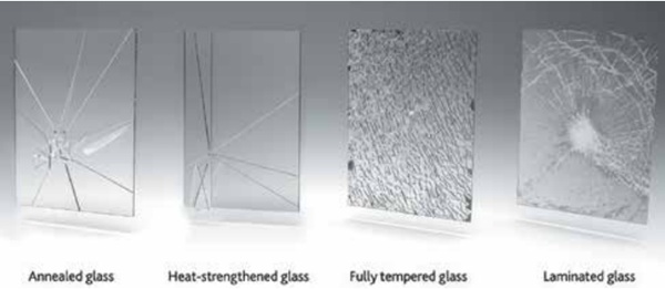
Crucially, NiS inclusions are generally not considered a risk for HS glass. This is attributable to the slower cooling process inherent in HS manufacturing, which affords any NiS inclusions present sufficient time to complete their phase transformation and expand while the glass remains relatively fluid, thereby precluding the impartation of significant additional stress into the glass. Therefore, spontaneous breakage attributable to NiS is primarily a concern for fully tempered glass. HS glass is frequently selected when additional strength is required to resist wind pressure or thermal stress, but the full strength or safety breakage pattern characteristic of tempered glass is not mandated. It is often employed in laminated configurations to achieve safety glazing properties by ensuring fragment retention.
MANUFACTURING PROCESS IMPROVEMENTS AND QC
The glass industry continuously strives to minimize the occurrence of NiS inclusions through various enhancements in manufacturing processes and the implementation of stringent QC measures. Efforts include meticulous sourcing of raw materials to mitigate nickel contamination and the avoidance of nickel-containing alloys in furnace components. Some manufacturers have also transitioned to cleaner fuels, such as natural gas, in lieu of oil, which may contain nickel oxide.
Notwithstanding these advancements, the complete elimination of NiS inclusions remains a formidable challenge, as they are microscopic and virtually impossible to detect reliably during online production with current scanning technologies. This inherent undetectability serves as a primary impetus for the reliance on post-production mitigation strategies such as HST.
Ongoing research and development initiatives are concentrated on refining detection methods and reducing the incidence of NiS. Emerging nondestructive detection technologies encompass ultrasound, laser imaging, photoelastic stress measurements, and X-ray diffraction, although these frequently necessitate the analysis of individual panes by skilled technicians. Innovations in glass composition, exemplified by borosilicate glass (for example, SCHOTT PYRAN Star), are also being investigated.13 These specialized glass types are engineered with chemical compositions that actively prevent the formation of NiS crystals, thereby eliminating or reducing the risk of spontaneous fractures and obviating the requirement for HST.
Furthermore, broader industry initiatives, such as decarbonization efforts in float glass production, may indirectly contribute to quality enhancements. Increased utilization of cullet can reduce melting temperatures and the demand for virgin raw materials, while fuel switching (for example, to hydrogen or biofuels) and increased electrification aim to reduce emissions. While these endeavors primarily target environmental impact, contamination control within these novel processes remains critical for maintaining glass quality, including NiS prevention.
Building Codes and Industry Standards
Building codes and industry standards regulate the application of glass in architectural contexts, particularly where safety is a paramount concern. The International Building Code (IBC) mandates the use of tempered glass in specific hazardous locations, such as glass adjacent to doors, windows, stairways, ramps, and in guards and railings, to prevent injuries resulting from shattered glass. According to the 2018 IBC Section 2406.4, the IBC mandates the use of tempered glass in specific hazardous locations.14 For overhead glazing, skylights, and glass floors, heat-soaked glass is highly beneficial and frequently recommended or required to comply with building standards and mitigate risk.
While European standards, such as EN 14179-1, rigorously specify the heat soak process for toughened glass, a direct American standard specifically for HST currently does not exist. Nevertheless, ASTM C1048 serves as the industry standard for HS and fully tempered flat glass, defining physical requirements and surface compression levels. Despite the absence of a specific HST standard, manufacturers recommend HST when fully tempered glass is mandated by code or design loads to minimize the risk of spontaneous breakage.¹⁵
It is pertinent to note that HS glass often fails to satisfy safety glazing code requirements due to its characteristic breakage pattern. Consequently, it is frequently employed in the form of laminated safety glass to ensure fragment retention and achieve compliance with safety standards. For projects involving high-rise facades, glass canopies, or balustrades, specifying HST-treated tempered glass and ensuring supplier capability and certification (for example, to EN 14179 or ASTM E2190, Standard Specification for Insulating Glass Unit Performance and Evaluation)¹¹ represents a critical consideration for risk mitigation and the assurance of safety compliance.
This article is intended as both a detailed technical analysis of glass breakage phenomena and a guide for improving quality assurance in glazing installations based on information available at the time of its creation. For inquiries regarding this analysis, further discussion on advancing testing methodologies, or additional technical insights, please contact the author.
REFERENCES
1. Barry, J. 2001. “Nickel Sulfide Inclusions in Tempered Glass.” Glass Magazine, March. Vienna, VA: National Glass Association (NGA).
2. Jacob, Leon, and Ignatius Calderone. 2003. “Nickel Sulphide Inclusions — Important Issues for the Designer.” In Glass Processing Days 2003: Conference Proceedings & PowerPoint Presentations. AIS 263. Tampere, Finland. www.aisglass.com/wp-content/uploads/2020/11/AIS-263.pdf (accessed Jan. 22, 2026).
3. Kasper, Andreas, John Colvin, Frank Rubbert, and Francis Serruys. (n.d.) NiS in HS glass. Technical Paper. Leicestershire, UK: Saint-Gobain Glass. www.saint-gobain-glass.co.uk/wp-content/uploads/2024/02/NiS-in-HS-Glass-ATechnical-Paper-2023_0-1.pdf (accessed Jan. 22, 2026).
4. AtomTrace. 2023. “Advanced Glass Analysis: LIBS for NiS Identification.” AtomTrace, June 14. www.atomtrace.com/news/advanced-glass-analysis-libs-fornis-identification (accessed Jan. 22, 2026).
5. Chung, Sung-Yoon, Young-Min Kim, Jin-Gyu Kim, and Youn-Joong Kim. 2009. “Multiphase Transformation and Ostwald’s Rule of Stages During Crystallization of a Metal Phosphate.” Nature Physics 5 (1): 68–73. www.condmatjclub.org/uploads/2008/12/jccm_dec08_01.pdf (accessed Jan. 22, 2026).
6. Martínez, Juan Pablo, and Diana Lohrer. 2025. “Invisible Danger: Safeguarding Glass from the Risks of Nickel Sulfide.” Glass on Web. www.glassonweb.com/article/invisible-danger-safeguarding-glass-risks-nickel-sulfide (accessed Jan. 22, 2026).
7. Serruys, Francis, Andreas Kasper, John Colvin, and Frank Rubbert. 2023. “Breakage Probability of Nickel Sulphide Inclusions in Heat Strengthened Glass.” Glass on Web. www.glassonweb.com/article/breakage-probability-nickel-sulphide-inclusions-heat-strengthened-glass (accessed Jan. 22, 2026).
8. ASTM International. 2004. Standard Specification for Heat-Treated Flat Glass — Kind HS, Kind FT Coated and Uncoated Glass. ASTM C1048-04. West Conshohocken, PA: ASTM International.
9. The International Organization for Standardization (ISO). 2017. Glass in building — Heat soaked tempered soda lime silicate safety glass. ISO 20657:2017. Geneva, Switzerland: ISO.
10. European Committee for Standardization (CEN). 2016. Glass in Building — Heat Soaked Thermally Toughened Soda Lime Silicate Safety Glass. EN 14179-1. Brussels, Belgium: CEN.
11. NGA. 2018. Heat Soaking Testing of Tempered Glass for Architectural Glass Applications. Glass Technical Paper FB56-18. Vienna, VA: NGA.
12. ASTM International. 2013. Standard Guide for Elemental Analysis by Wavelength Dispersive X-Ray Fluorescence Spectrometry. ASTM E1621-13. West Conshohocken, PA: ASTM International.
13. Future Architectural Glass. (n.d.) Technical Data Sheet SCHOTT PYRAN Star. Dubai, UAE: Future Architectural Glass. https://faglass.com/public/uploads/tech-file/US2VJQRHomc1knOMigr463REEl3al8xIXLPiweSU.pdf (accessed Jan. 22, 2026).
14. International Code Council (ICC). 2018. International Building Code. Country Club Hills, IL: ICC.
15. Viracon. (2024). Heat Soak Testing. Viracon Tech Talk, Bulletin ID: VTT-010. Owatonna, MN: Viracon. https://viracon.com/wp-content/uploads/2024/09/ VTT-010_HeatSoakTesting.pdf (accessed Jan. 22, 2026).
ABOUT THE AUTHOR
 Misael Rojas is a forensic architect with over 23 years of experience in architectural design, forensic investigations, construction, and building enclosure systems. As a leader in the field, he has contributed to the construction, investigation, and design of many buildings throughout the United States, as well as large-scale international projects. His deep expertise in building enclosures allows him to collaborate effectively with architects, clients, and contractors, ensuring well-integrated solutions from design to construction. Currently, he serves as a managing architect at Exponent and as an executive director on the board of IIBEC’s Metro New York Chapter. Licensed in multiple states, Misael operates nationally as a leading forensic architect while residing in northern New Jersey.
Please address reader comments to chamaker@iibec.org, including “Letter to Editor” in the subject line, or IIBEC, IIBEC Interface Journal, 434 Fayetteville St., Suite 2400, Raleigh, NC 27601
Part 2 coming soon - stay tuned for more insights on this topic.