This paper was first presented at GPD 2019 by Adam Nizich and Laura Galuppi.
The performance of laminated glass is commonly approximated with the Effective Thickness Method by Bennison, adapted from composite sandwich theory by Wölfel for a simply-supported beam under uniformly distributed load. Notably, significant underestimation of stress is observed with the use of stiff structural interlayer where cantilevered laminated glass support is modelled as an idealized fixedend moment.
This paper seeks to address the accuracy of cantilevered laminated glass balustrade analysis for practical design by investigating the applications of Enhanced Effective Thickness (EET) method by Galuppi & Royer-Carfagni. A new expression for the EET coefficient is proposed here for laminated glass balustrades supported by bearing in a continuous base shoe. Performance of the Effective Thickness Method adopted in ASTM E1300 and two expressions of EET are compared with numerical models for stress and deflection, with particular regard to Example 13 of ASTM E1300.
Introduction
The stiffness and strength of Laminated Glass (LG), formed by glass layers bonded together by polymeric interlayers, relies upon shear coupling between the glass plies by the polymer. Overall performance occurs between the two borderline cases referred to as the layered limit (i.e. frictionless relative sliding of glass plies, correspondent to the case of interlayer without stiffness) and the monolithic limit (i.e. perfect bond of plies, correspondent to the case of an interlayer with shear-rigidity).
For design purposes, it is very useful to define the Effective Thickness (ET) of LG, i.e., the thicknesses of an equivalent monolithic glass element presenting the same bending properties in terms of stress or deflection. Effective thickness methods greatly simplify structural calculations of laminated glass. Literature and lowercase "s" Standards record various expression for the ET.
Application of the Wölfel-Bennison (W-B) Effective Thickness Method [1], [2] for the design of cantilevered LG balustrade supported by a continuous base shoe is prevalent in international glazing industry literature, adopted in ICC-ES technical product approval ESR-3842 [3], and supported by a design example in ASTM E1300 [4]. Concerns have been raised about the accuracy of this popular analysis method for cantilevered LG balustrade based on stresses and deflections observed in numerical models for common support conditions. To improve accuracy for design, a modified application of the Enhanced Effective Thickness (EET) Method, proposed by Galuppi and Royer-Carfagni [6], for bearing support in a continuous shoe is here evaluated. The accuracy of ET methods for a linear load are compared with numerical models for different support conditions.
Continuous Support
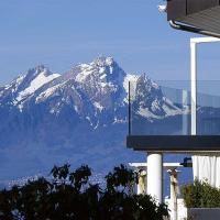
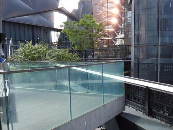
Ordinary cantilevered laminated glass balustrades are commonly supported by a continuous U-profile base-shoe. Monolithic glass or LG is seated approximately 70 mm to 100 mm into the profile and secured by either a wet or dry glazing method to remove rotational tolerance by injected grout / epoxy, or periodically spaced wedge blocks, respectively. No distinction is made to glass structural performance whether wet or dry glazed to manufacturer specification [3]. The accuracy of periodic support compared to truly continuous support is not evaluated in this paper, but warrants further study.
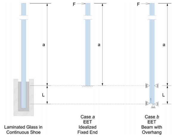
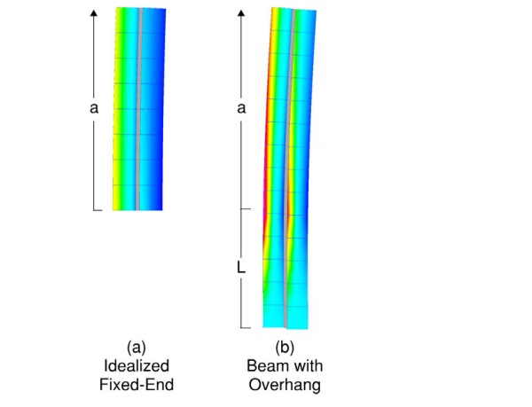
The mechanics of cantilever support may be modelled by different boundary conditions, as shown in Figure 1. Boundary conditions idealized as a fixed-end moment (a) requires the development of glass layer axial forces reactions at the support. The alternate boundary conditions of a beam with an overhang (b) permits slip to occur between glass layers at the supported end. Axial support is provided to one glass layer to prevent free-body motion. Analysis of either support condition for monolithic glass results in the same stress; and for a relatively short distance L between supports compared to cantilever length a, practically identical displacement. Evident in numerical evaluation, the performance of cantilevered LG is different for the mechanics of each cantilever support condition.
Development of an idealized fixed-end moment of LG in an ordinary balustrade shoe requires clamping friction or adhesion to prevent slip of the glass layers. Baidjoe, et al. [5] demonstrated that ordinary shoe flexibility causes rotation in one leg of the profile, qualitatively reducing the effectiveness of clamping or uniform adhesion. There are installations where slip could be plausibly be prevented at ultimate design loads. However, particular attention must be given to validate the assumption of favorable performance, including substantiation of forces, compatible deformations, and verification of installation by a qualified inspection method.
Consideration of the support conditions is made in modification of the EET method to provide a more accurate estimate of cantilevered LG performance subject to a linear load. Comparison of numerical models with ET models for (a) idealized fixed-end and (b) bearing support conditions, is made.
W-B Effective Thickness Method
The prevalent Enhanced Thickness model proposed by Bennison [1] is based on an original work by Wölfel [2], and adopted in ASTM E1300 [4]. To illustrate this method, consider a beam of length L and width b whose cross section, shown in Figure 2, is composed of two external glass plies of thickness h1 and h2 with Young’s modulus E, bonded by a soft polymeric interlayer of thickness t and elastic shear modulus G. Let:
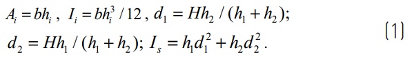
The W-B approach prescribes the following expression for the deflection, and the stresseffective thickness of the first and second glass plies i, respectively:
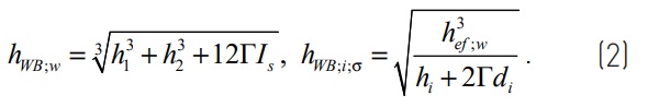
where the shear coupling coefficient Γ is evaluated with reference to the very particular static scheme of a simply supported beams under uniformly distributed load. Nevertheless, these expressions are frequently used in numerical computations to estimate the state of stress and deformation of LG beams and plates under common boundary and load conditions.
Example 13 of ASTM E1300 [4] purports to offer an ET solution for cantilevered LG subject to a linear load per the W-B effective thickness method. The development length of the interlayer corresponds to the cantilever overhang dimension a. This results in a lower bound solution compared to an idealized fixed end support (case a), however, the boundary conditions are not substantiated in this adaptation of the W-B ET method for simplysupported beams.
Enhanced Effective Thickness Method
A more general formulation, called Enhanced Effective Thickness (EET) method, has been proposed by Galuppi and Royer-Carfagni [6]. It is based upon a variational approach that, through strain energy minimization, finds the best approximation for the response of laminated glass. The method, which can be extended to the two-dimensional case of plates [7] and multilaminates [8], has been mentioned in the upcoming Eurocode 11 for structural glass [9].
The main assumptions for this model are: (i) the effective inertia of the LG package is the weighted harmonic mean of the inertia associated with the monolithic and layered limits; (ii) the exact value of the weight parameter can be found through energy minimization; (iii) the deformed shape of the LG beam has the form of the elastic curve of a monolithic beam with constant cross section under the same loading and boundary conditions.
For LG elements made of two glass plies, the deflection and stress-effective thicknesses can be evaluated as:
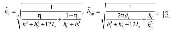
where the parameter η, tuning the behavior from the monolithic limit (η=1) to layered limit (η=0), is given by:
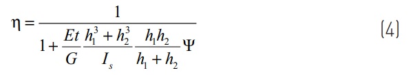
Effective performance turns out to be dependent on the mechanical properties of both glass and polymer, the geometric characteristics of the LG package, on the boundary and loading conditions. Values of the coefficient Ψ are recorded in [10] for design cases of most practical relevance. As discussed in [11] for balustrades, and in general for asymmetric static schemes, and/or for support conditions where glass plies are free to move in the axial direction, the EET model must be modified to account for the possibility of a rigid displacement of one glass ply with respect to the other.
More precisely, whenever the axial displacements of the two glass plies are not constrained to be the same at a given point, there may be a reciprocal translation, not altering the stress state of the glass plies but tending to minimize the interlayer strain energy. This reduces the shear stress transmitted by the interlayer and, consequently, the degree of coupling between the glass plies and the resulting effective thickness of the beam.
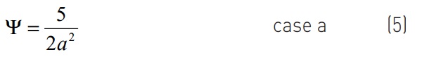
Values of coefficient Ψ are obtained in [11] by means of energy minimization techniques, for different loading and boundary conditions. For the cases considered here, they are:
Support as idealized fixed-end moment:
Support as beam overhanging one support:
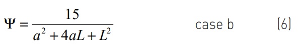
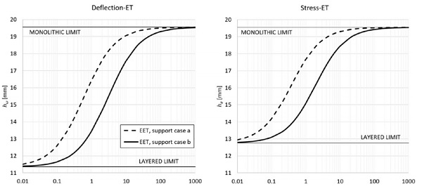
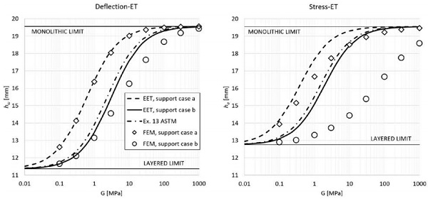
Figure 3 shows the comparison of the deflection- (on the left-hand-side) and stresseffective thickness (on the right-hand-side) obtained for case (a) and case (b) boundary conditions. Considered geometry is defined by: h1 = h2 = 9.02 mm, t = 1.52 mm, a = 1100 mm for the cantilever, and L = 50 mm for the distance between supports (case b).
From a qualitative point of view, it may be observed that whenever the two glass plies are free to translate with respect to one another in the axial direction (support case b), the shear coupling decreases, leading to lower values of effective thickness, for a given value of G.
Numerical Analysis
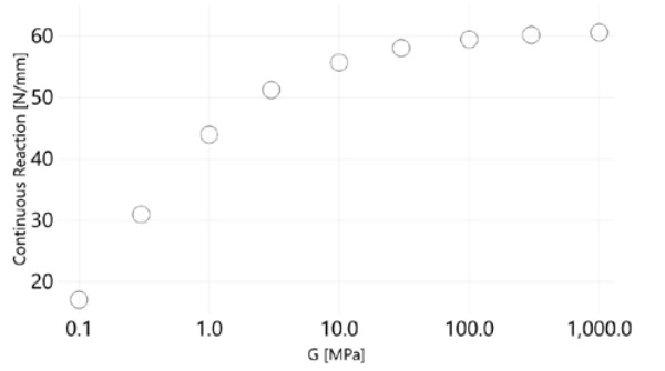
Identification of an appropriate modeling technique was not an intended outcome of this study, but unmistakably a required step for comparison of support cases a & b. Numerous modeling techniques were evaluated including layered elements, 2D plane strain, and 3D brick models without link constraints, as well as isotropic, rubber, and equivalent spring laminate properties for the interlayer. Given the high reaction forces and restraint pattern (Figure 1), the more detailed meshes were prone to artificial nodal stress concentrations at restraints.
Convergence was found with a simpler QUAD4 plate model for glass, connected to an offset HEX8 laminate core with rigid links in Strand7 [12]. Furthermore, expected deflection and stress results for support case (a) were verifiable with this technique and justifiable for case (b). Subdivision of the plate elements for the glass was 10 mm square. A 1-parameter Neo-Hookean rubber model was used to improve compressive performance of the laminate.
Bulk modulus and the material constant parameter of the rubber model are proportional to known elastic moduli and Poisson’s ratio, so assumption of additional mechanical properties was not necessary. Glass properties E = 71.7 GPa, v = 0.22 and thickness tolerances were adopted from ASTM E1300 [4], and a 0.73 kN/m linear load was considered for direct comparison with LG balustrade design practices for linear loads in the United States [13], and of similar magnitude for Canada [14]. Considered geometry is the same of the previous Section.
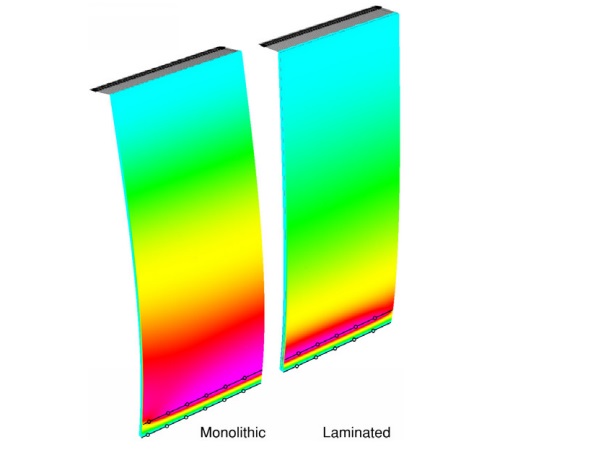
In comparison of monolithic and laminated glass balustrade subject to a linear load, a difference in the tensile surface stress field is evident (Figure 4). This discrepancy is due to the fact that the overall inertia of the LG beam depends on the shear stress transmitted by the interlayer. Since the shear strain, and consequently the shear stress, is variable along the beam axis, the LG cantilever behaves as a beam with variable inertia along length x, which leads to a more complicated axial stress distribution along the beam axis. In comparison to support (b), an axial reaction is developed at each glass layer in the idealized fixed-end moment support (a) preventing slip (Figure 5).
To achieve the idealized fixed-end support case (a), development of the glass layer axial forces as depicted in Figure 6 is required. Spread over the 50 mm effective support, the equivalent shear stress τ > 1.0 MPa for stiff interlayers for the nominal design load.
Comparing numerical results with ET models (Figure 7), the analytical “modified EET” model is quite accurate for deflection, even if it tends to overestimate the ET for moderate values of G, with a max percentage error on the order of 8%. This is thought to be the result of a variable strain distribution in the interlayer which is much greater than the average distribution assumed in the EET model.
On the other hand, it is evident that the ET models are not able to correctly capture the stress-effective thickness. This is due to the strong difference of the stress distribution in the equivalent monolithic and laminated beam, as discussed before. Stress-EET for support case (b) is significantly overestimated, with a max percentage error on the order of 28%.
Overestimation of ET is reciprocal to underestimation of deflection and stress. As a result, design stresses determined from Example 13 in ASTM E1300 are underestimated by 40%. In other words, the design stress estimated by the Example 13 method is off by a factor of 1.67 in this case. Due to the magnitude of inaccuracy, it is not currently possible to define a monolithic element, with a certain thickness, behaving as the considered laminate where stress is concerned. This remains the current limitation of all ET models.
This limitation may be overcome by studying more refined models [11], accounting for the variation along the beam axis of the coupling ensured by the interlayer, and, consequently, of the effective stress distribution in the laminated element.
Conclusion & Summary
The W-B effective thickness model and example in ASTM [4] does not provide accurate results for the evaluation of LG balustrade. The modified EET [11] is more accurate for deflection than former models for an overhanging beam bearing between two supports. However, the stress distribution and proximity of the constraints is very different in laminates and monolithic glass elements. Thus, the currently used ET models (based on the definition of a monolith with constant inertia behaving as the considered element) cannot be used to accurately evaluate the stress.
Of particular concern is the magnitude of inaccuracy for all stress ET methods where G = 10 MPa, which consequently corresponds to the design range of temperature-duration mechanical properties of stiff interlayers [15]. Extra-stiff PVB and Ionomer interlayers with improved service and post-breakage performance are gaining prevalence as prescribed for tempered-tempered LG in CSA A500 [16], and are the basis for selection of thinner LG compositions in ESR-3842 [3].
Further numerical evaluation and accurate laboratory testing are necessary to clarify actual performance of laminated glass supported by ordinary balustrade shoes. Correction of test methods must be made to address these observed fallacies: i) rotation at supports, ii) deflections within a small magnitude of deviation from ET methods offer a false impression of stress performance, and iii) new tempered glass is statistically stronger than glass in service and frequently of a higher residual compressive surface stress than minimum specification.
More refined Enhanced Effective Thickness methods are currently being studied [11] to more accurately capture the response of balustrades for preliminary sizing and to identify a universal standard of structural analysis for laminated glass.
References
[1] Calderone, I., Davies, P.S., Bennison, S.J., Xiaokun, H., Gang, L. Effective laminate thickness for the design of laminated glass. In: Proceedings of glass performance days, (2009) Tampere (FI).
[2] Wölfel, E., Nachgiebiger Verbund Eine Näherungslösung und deren Anwendungsmöglichkeiten. In: Stahlbau. (1987) 173-180.
[3] ESR-3842. GRSTM Glass Balustrade Guard System for Laminated Tempered Glass Applications, C.R. Laurence Company, Inc., ICC-ES Evaluation Report, (3:2018)
[4] ASTM E1300-16. Standard Practice for Determining Load Resistance of Glass Buildings, ASTM International, West Conshohocken, PA (2016)
[5] Baidjoe, Y., et al., Calculation methods of glass parapets in aluminium clamping profiles, Glass Struct. Eng., (2018) 3:321-334
[6] Galuppi, L., Royer-Carfagni, G., Effective Thickness of Laminated Glass Beams. New expression via a variational approach, Eng. Struct., 38 (2012) 53-67.
[7] Galuppi, L., Royer-Carfagni, G., The effective thickness of laminated glass plates, J. Mech. Mat. Struct. 7 (2012) 375-400.
[8] Galuppi, L., Royer-Carfagni, G., Enhanced Effective Thickness of Multi-Layered Laminated Glass, Composites: Part B, 64 (2014) 202–213.
[9] CEN/TC 250. prCEN/TS xxxx 2:2018 - Structural glass - Design and construction rules. Part 2: Outof-plane loaded glass components. (2018)
[10] Galuppi, L., Manara, G., Royer-Carfagni, G., Practical expressions for the design of laminated, Composites: Part B 45 (2013) 1677–1688.
[11] Galuppi, L., Nizich, A. “Cantilevered Laminated Glass Balustrades: modified EET approach and design issues”. In preparation, (2019).
[12] Strand7, 2019. Strand7 Finite Element Software, R3 Preview, Strand7 Pty Limited, Sydney (AU).
[13] ASCE 7-16. Minimum design loads and associated criteria for buildings and other structures. American Society of Civil Engineers. (2017), Reston, VA
[14] NBC-10. National Building Code of Canada. National Research Council of Canada. Ottawa, ON. (2010)
[15] Kuraray. Structural & Security: Trosifol Technical Data. (10:2018)
[16] CSA A500-16. Building Guards. CSA Group. Toronto, ON. (9:2016)
Acknowledgements
A special thank you to the Department of Engineering and Architecture, University of Parma, for their enthusiasm to identify simplified solutions to laminated glass design. Thank you to the Walter P Moore Enclosure Engineering team for their assistance and support advancing this topic.