Authors:
- Thiemo Fildhuth - Lucerne University of Applied Sciences HSLU
- Pascal Joos - Lucerne University of Applied Sciences HSLU
- Thomas Wüest - Lucerne University of Applied Sciences and Arts, CC Building Envelopes and Civil Engineering
- Matthias Haller - Solutia Deutschland GmbH
- Wim Stevels - Eastman Chemical bv
Source:
Glass Structures & Engineering | https://doi.org/10.1007/s40940-022-00198-6
Abstract
Intended for the construction of a double curved, frameless modular glass shell demonstrator, a stainless steel fitting connection with a trapezoidal, thin sheet laminated into the interstice of two-ply safety glass has been developed. For the bonding within the glass laminate, structural PVB interlayer is used. Various interlayer plies of different PVB types can be stacked depending on the necessary interstice thickness and the intended esthetical appearance. The fitting is designed to mainly transfer translational forces, but it also provides some bending stiffness via a crossbar supported against the glass edge.
Various tests, including tension, shear and bending load application, have been performed at the Lucerne University of Applied Sciences and Arts (HSLU) to explore the structural behavior and the load bearing capacity of the fitting connection. In addition, parameter studies using finite element models were made to explore the influence of the fitting geometry, dimensions, interlayer properties and loading type on the structural behavior of this type of connection. These parameter studies and test results allow to identify further shape optimization and application possibilities of such thin, laminated fittings for load bearing glass structures.
Introduction
Background
Designing and building structural, glass-only shells is subjected to two principal boundary conditions: The use of planar or curved glass laminates with limited dimensions and the necessity to provide a structural joint between the adjacent glass modules. These structural connections mainly transfer in-plane membrane forces (axial component and shear parallel to the glass edge), but the passage of out-of-plane forces and, subsequently, the provision of a limited bending stiffness about the glass edge are also necessary to cope with asymmetric loads and for global stability of the shell.
Furthermore, sufficient stiffness of the connections is mandatory for the assembly and correct geometrical orientation of the glass modules in the context of the global shell geometry. The position and orientation of the joints with respect to the shell global shape and the loading scenarios are crucial for the forces to be transferred in the connections (Fildhuth and Knippers 2012; Fildhuth and Lippert 2012, Bagger 2010). Furthermore, the joints constitute a discontinuity with distinct stiffness variation in the shell surface. The same holds for structural glass connections in plate-like glass constructions.
Apart from classical point fixings or shear bolt connections with holes through the glass (e.g., Baitinger 2009), the most widespread, though complex, structural glass connections are stainless steel or titanium fittings being laminated into reservations / pockets cut out of the central glass lite in multi-layer glass laminates with a minimum of three or often five lites (O’Callaghan 2012, Bedon 2018). Point-like connection elements adhesively bonded to the glass surface using different adhesives or polymer films have been shown and examined, e.g., by Kothe (2016). Linear connections are either direct adhesive butt joints between adjacent glass panes (Blandini 2005), or mixed designs with bolt-connected metal rails linearly bonded to the glass edge (Veer 2003). Edge-bonded local connections are presented by Schulz (2021) and Ioannidou-Kati (2018).
Marinitsch (2015 & 2016) developed a complex, strong linear connection consisting of a metallic edge profile with protruding parts being laminated into the glass compound. A comprehensive work on fittings laminated into the interlayer zone with ionomer interlayer and shape optimization studies has been delivered by Puller (2012). A more recent publication (Volakos 2020) presents an interstice-laminated metal sheet connection using transparent cast resin and is interesting for comparison with the present paper. Carvalho (2011) proposed interstice-laminated perforated metal sheets for connections. A variation of laminated structural fittings situated at the vertices /corners of static glass elements or doors has been developed and applied by Kassnel-Henneberg (2020) and (2017).
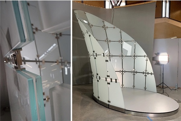
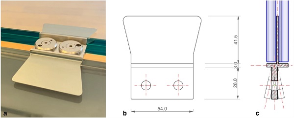
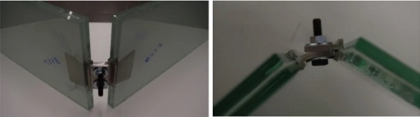
The desire of Eastman to present the structural capacity of the interlayer Saflex® Structural (DG41) on a trade fair and to exhibit the possibility to use stacks of various interlayer types to achieve architectural design objectives such as coloring or translucency led to the development of a modular, frameless, 4.20m tall glass shell as a demonstrator (Fig. 1) by engineering firm knippershelbig from Stuttgart (Schieber et al. 2021). The structural joining of the two-ply glass laminates (8.8mm heat strengthened glass) is achieved by stainless steel fittings with dovetail-like, 1.5mm thin steel blades that are laminated in the 3mm interstice between the two glass layers (Fig. 2), making use of the shear stiffness properties of the structural PVB interlayer (Stevels 2020).
The variable angle of the connection lugs (Fig. 2c), that depends on the shell shape, is chosen in the design phase prior to the milling of the individual fittings. Apart from the shell development itself, a testing program of the structural fitting connection was performed at the building envelope competence center (CC GH) at the Lucerne University of Applied Sciences and Arts. Detailed results are provided below. A summary of the global test results and the underlying interlayer properties are presented in a paper by Stevels (2022).
Original development of the fitting connection
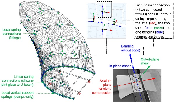
The design development and construction design of the fitting have been performed by knippershelbig based on publications on laminated metal strips with structural PVB (Louter and Santarsiero 2019) and manufacturer material data of the structural PVB material (Eastman 2020, Stevels 2020, Schuster 2021). The fitting transfers forces for all three translational degrees of freedom and for rotation about the glass edge, where a limited bending stiffness is provided by the fitting (Fig. 3). Within the numerical model of the shell, the fitting connections were modelled via four springs per connection (Fig. 3). The bending stiffness is achieved by the T-crossbar of the fitting, that is bonded to the glass edge by structural PVB, too.
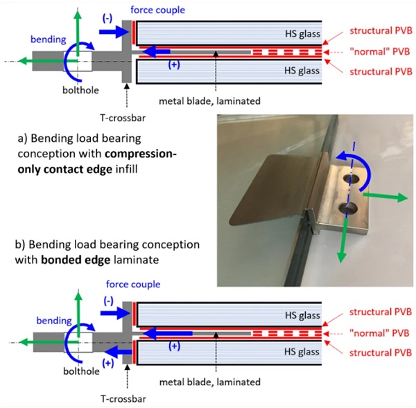
The PVB used for the 1.52mm thick edge bond is the same structural PVB as used for lamination of the glass sheets. The mixed load bearing behavior can thus be characterized by two approaches: Bending is either supported by a force couple with tension in the laminated steel blade and compression between one flange of the crossbar and the glass edge (Fig. 4 a) in a conservative approach without edge bonding, or the force couple is developing in the two flanges of the crossbar assuming an intact edge bond (Fig. 4 b). Ultimately, the conservative approach was applied for the shell design. In-plane translation forces are mainly supported by shear action in the interlayer between the laminated blade and the glass. In reality, the fitting shows a complex, mixed load bearing behavior activating both the laminated part and the edge bond.
The safety concept of the shell locally relies on the ductile behavior of the fitting, which fails without rupture either in delamination (in-plane forces) or steel plastification (bending) and thus globally allows for activating alternative load paths along intact fittings in the shell. Thus, in case of a fitting failure by delamination or plastification, a post-failure load bearing capacity remains both by the fitting itself and by alternative load paths via intact fittings in the vicinity.
For the shell construction and assembly, it is crucial to correctly place the fittings in the laminated glass with respect to their location and the angle. Tolerance is provided by oversized holes in one of each fitting pairs. After bolting, these holes are filled with injection mortar (Fig. 2a).
Two bachelor theses (Yersin 2020, Joos 2021) have been established in parallel by students at the HSLU to support the design process by detail and parameter studies of the fitting connections, see also section 2. During the development process, the originally rectangular laminated steel plate was optimized towards a dovetail design to reduce stress and improve the optical appearance.
Currently, the fittings are milled from stainless steel 1.4301 as one single piece, including the 1.5mm thin blade. Each fitting can be manufactured individually with respect to the connection lug angle. Lamination is established in a vacuum-bag in the autoclave. The interlayer is applied in four stacks of 0.76mm. The layers in-between the fitting blade and the bond are crucial for the shear bond of the fitting and are always made from transparent structural PVB (Saflex® structural, “DG41”). The two layers in the core can either be colored or translucent conventional PVB (“RB41”, Vanceva® Arctic Snow in the case of the shell) or transparent structural PVB DG41, too. A fully transparent stack, however, is aesthetically beneficial for the light appearance of the shell and in reducing the visibility of the fittings.
Numerical analyses of the fittings
Intention
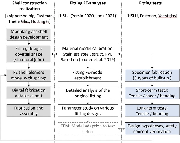
The development of the demonstrator modular shell and the fitting connection was performed by knippershelbig engineers in Stuttgart (Schieber 2021) in a short period due to the project schedule. The global shell model was numerically simulated with shell elements and spring connections using the software Sofistik 2020. Two bachelor theses at the University of Applied Sciences Lucerne (Yersin 2020, Joos 2021) provided additional studies for the development and understanding of the laminated fittings. The detailed numerical analyses by Joos (2021), shown in sections 2.2 and 2.3 below, include parameter and sensitivity studies and focus on the load bearing behavior of the trapezoidal fitting design used for the demonstrator. Based on this, various geometrical parameters and shape alternatives have been studied both for local fittings and a linear edge fitting (see section 4). The entire procedure is schematically shown in Fig. 5.
Model setup, parameters
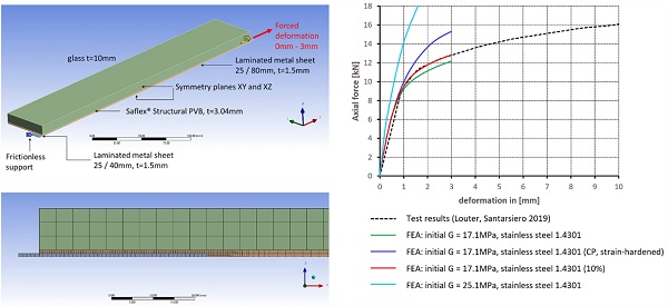
Numerical modelling (Joos 2021) was performed applying the FE-software Ansys 2020 R2. As no direct tests were yet performed during the development of the shell and the fittings, the numerical models of the fittings were based on test data from publications, notably (Louter, Santarsiero 2019) for tensile tests on laminated metal sheets and (Eastman 2020, Stevels 2020) for interlayer data. Higher-order volume elements, non-linear material models and geometrically non-linear analysis were applied in all FE-models.
The stainless steel was implemented using the multi-linear isotropic hardening material law and the non-linear stress-strain curve according to the method described in (Informationsstelle Edelstahl Rostfrei 2017). For all PVB, the moduli data provided by the manufacturer were curve-fitted to obtain a Prony series description. Based on this, the variation of material parameters to calibrate the model to (Louter, Santarsiero 2019) for a path-controlled test with 1mm/min at 20 °C led to applying an initial shear modulus of 17.1MPa for the PVB and a 10%-increase of the yield point of the stainless steel. (Fig. 6)
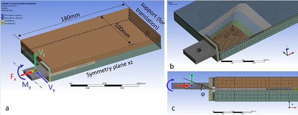
The calibrated material models were then applied to the numerical model of the stainless steel fittings. The two-axial symmetry fitting model included sufficient laminate volume around the fitting to cover all disturbance zones (Fig. 7a). The translation loads were applied to the lug plate of the fitting in the bolt hole zone either as a forced deformation of 1mm in axial or shear direction (Fig. 7a, c) and the plate was supported at the rear side. For applying bending (5°) about the edge of the glass by rotation (angle ϕ), the front surface of the lug plate of the fitting was used (Fig. 7 a, c) and the support conditions were adapted. It must be noted, however, that the boundary conditions (supports) of the FE-models are adapted to the situation present in the modular glass shell and thus partially differ from the supports applied in the tests (compare section 3.2 below, Fig. 12).
The mesh was refined in the critical zones, notably in the boundary zones of the laminated fitting and the PVB interlayer. Two elements were used through the thickness of the interlayer between the fitting metal sheet and the glass.
Summary of the numerical results
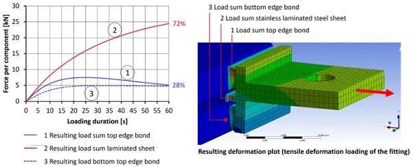
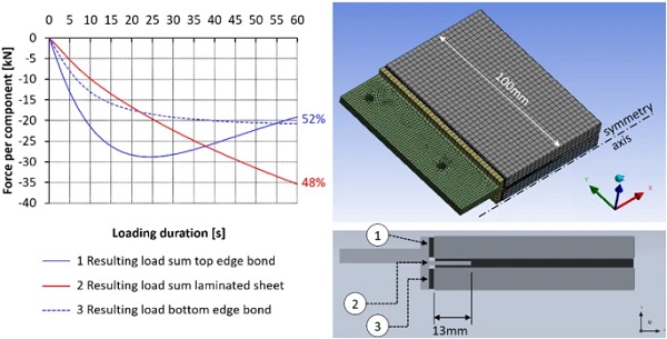
Applying short-term tension to the fitting by a 1mm axial displacement leads to shear-transferring the main part of the resulting load into the glass via the laminated metal sheet of the fitting (Fig. 8). Increasing loading time causes decreasing load transfer (axial tension) via the edge bond of the crossbar. However, the asymmetric shape of the fitting due to construction reasons always causes limited bending that leads to a slight rotation of the fitting about the glass edge.
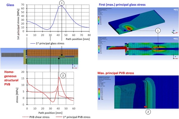
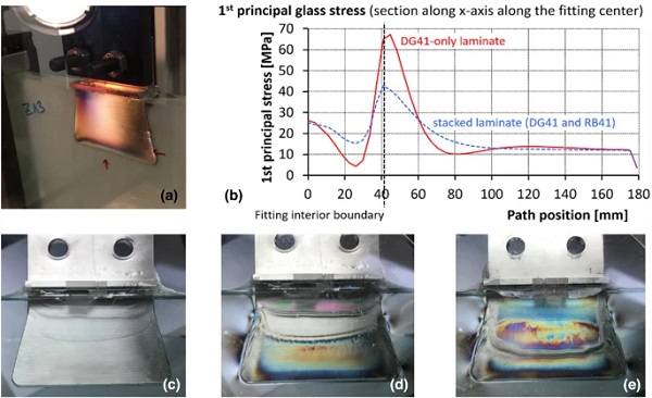
The shear stress in the structural PVB between the 1.5mm thick fitting sheet and the glass is relatively constant along a path from the edge to the end of the sheet and exhibits shear stress peaks at the glass edge (Fig. 9) and, much more prominent, at the end of the laminated sheet (40 mm depth). The first principal stress in the PVB shows tensile maxima at the glass edge and at the fitting sheet end in the laminate together with a linear stress change along the fitting depth and a stress minimum at approximately 30 mm depth into the laminate. Analogously, the glass is also subjected to maximum tensile stress in the discontinuity zone at the end of the laminated fitting sheet (Fig. 9).
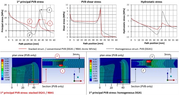
The composition of the interlayer influences the load bearing and failure behavior, as can also be seen from the test results (section 3). A homogeneous interlayer build-up from structural PVB (DG41) exhibits lower principal PVB stress along the fitting compared to a stacked buildup from DG41 and standard RB41 PVB (Fig. 10). However, the stress peak at the interior end of the fitting is higher and broader for the homogeneous interlayer composition from DG41 only. The same holds for the shear and hydrostatic stress (σhydro = (σ11 + σ22 + σ33)/3) along the fitting laminate and for the principal tensile glass stress. In the test, however, the stacked laminates (DG41 + RB41) failed in glass breakage for the tensile test, while all homogeneous DG41-specimens failed in fitting PVB delamination (see section 3).
If the fitting is loaded in short-term bending (rotation of 5°) about the axis parallel to the glass edge, it is mainly the crossbar bonded to the glass edge that transfers load via a resulting axial force couple; the laminated metal sheet only introduces about 10% of the total load to the glass via shear in the PVB.
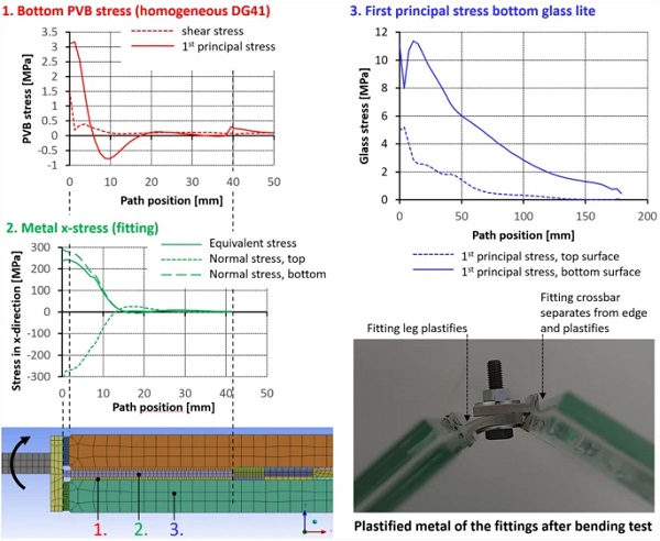
In bending, the metal of the fitting is governing for the connection, as it is subjected to high stress and thus tends to plastify along the first part of the laminated metal sheet (Fig. 11, diagram 2.) and, with increased rotation, in the exterior “T”-shaped part (Fig. 11, test photo). PVB stress remains rather low and exhibits principal stress and shear maxima along the first 5mm into the laminate (Fig. 11, diagram 1.). The principal glass stress maximum occurs at approximately 20mm depth (path in x-direction, see Fig.11, diagram 3.) and decreases constantly with increasing x-distance from the glass edge. These findings correlate with the visible metal yield and the glass failure in the fitting zone occurring in the bending test at an extreme rotation angle (section 3, Fig. 20).
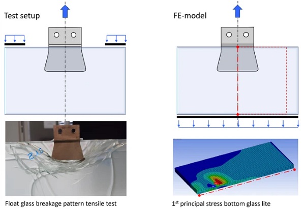
The FE-analyses shown were performed prior to the tests in the context of the design of the demonstrator glass shell. Thus, they have boundary conditions differing from the tests, where, e.g., the specimens were supported at two zones at the top in the tension test (Fig. 12). Additional FE-analyses adapted to the test conditions are thus necessary to allow more direct comparison of the test results and the numerical model. The test setup and results are shown in detail below.
Testing
Test motivation and intention
As the development process of the fittings was originally entirely based on published material data and numerical models, tests of the fittings have been performed at the HSLU to verify and to hedge the theoretical assumptions applied for the original design of the structural joints and the shell. Furthermore, the safety concept of the glass demonstrator shell could be verified with respect to the strength, ductility and post-breakage behavior of the fitting connections. In addition, the tests were intended to deliver additional data for the calibration of the spring models used in the joints of the demonstrator.
An overview of the key numbers and figures has been published in the paper (Stevels 2022). The test results and the FE-analyses currently allow only partial comparison for the case of the tensile tests because of the different boundary conditions (Fig. 12) resulting in different load paths. However, a main objective is to verify the safety concept of the fitting connection relying on ductility and post-breakage load bearing capacity. The potential influence of various interlayer stacks using different PVB material is also examined.
Test setup and methods
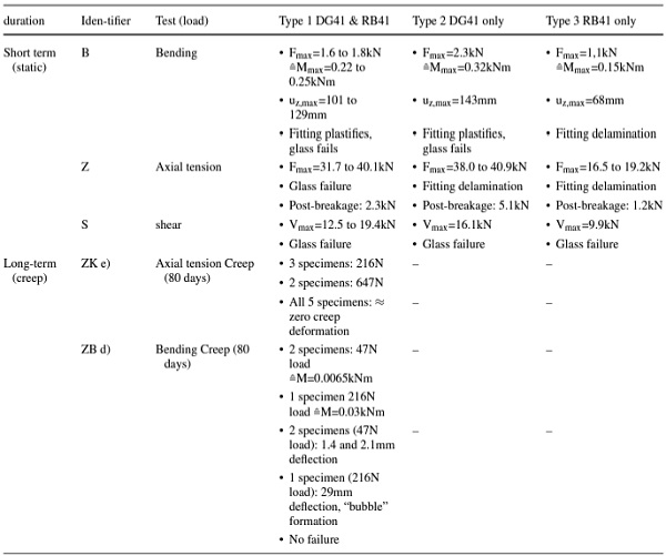
Two types of tests were performed: In the short-term static tests the tensile, shear and bending performance was investigated. Long term tests for tensile and bending were carried out to gain information on creep. While the bending performance is important for the joint construction/geometry and the overall stability of the shell especially against asymmetrical and concentrated loads, the creep behavior is of interest, as permanent loading of the joints cannot be fully avoided in the shell.
Table 1 Test setup and specimen overview - Full size table
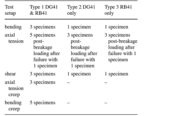
To minimize the production effort, the test specimens were designed to conduct the various tests with a minimum of sample configurations. Therefore, a uniform basic specimen geometry of rectangular laminates 200mm x 550mm (8.8mm float glass, 3mm PVB) was used. For tensile tests, the fitting was centered at the long edge (550 mm), for shear and bending at the short edge. A Zwick/Roell 150kN tensile and compression testing machine with path-controlled load application was applied (1 mm/min tensile & shear, 10 mm/min bending). All testing was performed at room temperature (20–21 °C).
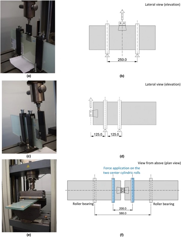
For tensile testing, the specimens were held down by two steel braces (Fig. 13 a, b)). Aluminum support blocks were used to avoid steel contact. A screw-based jig ensures immediate load application and avoids misalignment of the specimens. Tensile loading is applied by pulling the fitting, situated at the center of the long edge, upwards. The shear test (Fig. 13 c), d)) was conducted in a similar setup with the two braces and pulling upwards the fitting laminated at the short edge of the specimen. Four-point bending tests on two specimens connected via fittings were inspired by the EN 1288-3 setup but used a reduced support span of 550 mm to suppress dead load influence (Fig. 13 e, f)).
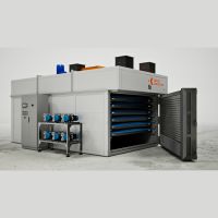
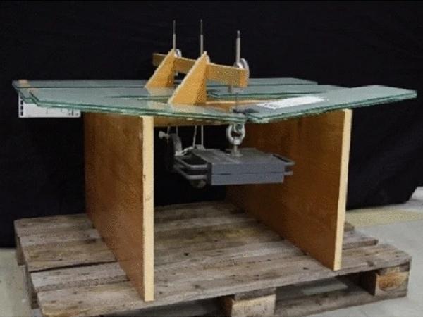
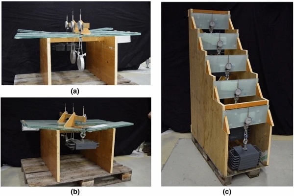
For long term load application (creep tests), suitable transportable racks were manufactured to support the specimens and to apply the permanent load (Fig. 14). Testing was performed for a duration of 80 days in a conditioned room at a temperature of 21 ± 1 °C. Deformation was measured by analogue dial gauges with 1/100 mm resolution. The loads of 4.8 kg (bending creep) and 22 kg (axial tensile creep force) applied in the tests correspond to permanent fitting loads determined via FEA of the glass demonstrator shell. In addition, much higher tensile (66 kg) and bending (22 kg) creep loads were also used for the sake of comparison.
Test results
Bending
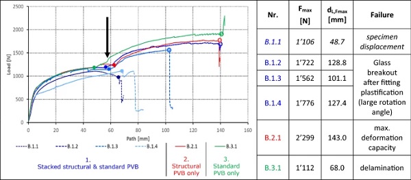
All configurations show a ductile behavior and local glass failure, typically of one lite only, is observed only with high deflection in terms of very high rotational deformation in the joints. The type 3 configuration delaminated as the only one. The black arrow in the graphs in Fig. 15 indicates the point at which plastification of the fitting and / or delamination of the edge bond have reached a deformation that causes contact of parts of the bolted fittings between each other and thus initiates a second increase in load until the glass breaks or the fitting delaminates, both without losing the integrity of the entire connection.
Axial Tension
The type 1 and type 2 specimens act very similar in deformation path as well as maximum load (Fig. 16). Type 3 specimens are, due to the different PVB, less rigid and delaminate on significant lower loads. Glass breakage is only observed on the Type 1 configurations with stacked interlayer. Glass failure and delamination never caused disintegration / falling apart of the fitting connections.
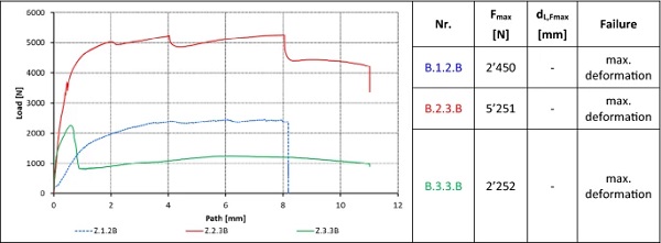
One of each laminate configuration was tested a second time to gain information about the post delamination / post failure behavior. All specimens show a considerable post delamination/ failure load capacity (Fig. 17).
Shear
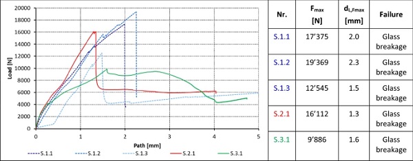
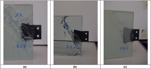
In all cases, the failure was glass breakage starting at the front edge near the fitting (Fig. 18). Specimen S.3.1 shows glass breakage only in one lite. During the test, the deformation was concentrated on the broken glass part.
Creep - In-Plane Axial Tensile Load
For long term axial tensile load, no measurable deformation has been recorded neither for the typical load (0.22kN) nor for the increased load (0.65kN) at room temperature. Due to the asymmetric fitting, a slight rotation could be observed at the 0.65kN test. (Table 2)
Creep - Bending
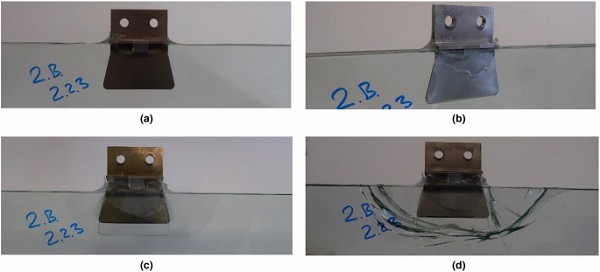
The creep bending test was performed for 80 days in a climate conditioned chamber (room temperature). The typical maximum design bending load from the global shell FE model (0.0065kNm) caused only very small creep rotation during 80 days at room temperature. A massively increased bending load of 0.03kNm, however, exhibited pronounced creep rotation (Fig. 19) and started to develop bubbles in the interlayer bond (Fig. 19 b)) towards the end of the test.
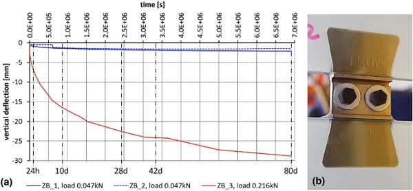
Table 2 Test setup and result overview; results: greyish background. - Full size table
Test result overview
The loads and result overview are given in Table 2 below. Shear tests suffered obvious glass failure occurring much sooner than potential interlayer failure due to the use of float glass.
Bending Load Test
As also shown in (Stevels 2022), the bending test show very high rotational capacity. The stacked interlayer samples were bent to about 127° and 111° (starting at plane 180°), see Figure 20. Three rotation phases can be distinguished: 1. linear rotation of the connection, 2. plastic rotation of stainless steel fitting and 3. mechanical contact of fittings which causes a further load increase. Two stacked specimens and one pure DG 41 sample even reached a maximum rotation angle of 104°. Such excessive rotation finally caused one glass lite to break directly at the fitting (Fig. 21). The pure translucent white PVB (RB41 only) samples exhibit a first linear rotation phase followed by a second, also linear deformation until laminate failure. It was observed that the stainless steel rotation capacity was not fully exploited when the delamination started, because the T-crossbar delaminated from the edge and started to pull-out the laminated fitting sheet.
In-Plane Axial Tensile Load (Pull Test)
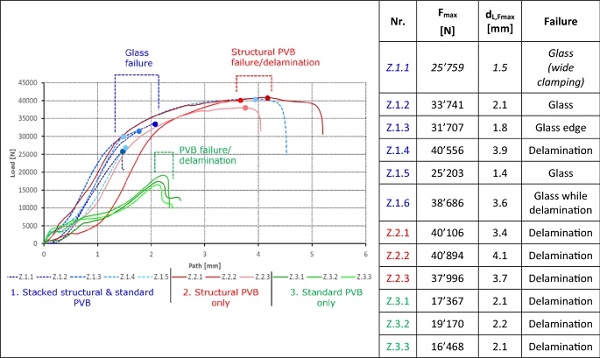
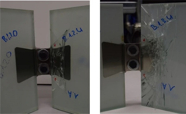
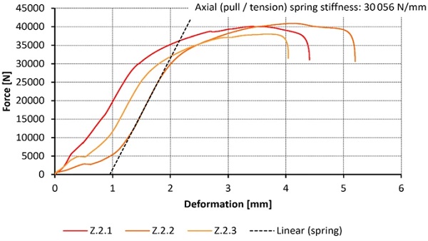
The structural PVB (DG41) bond between fitting and glass dominates the resistance. Both laminate configurations, stacked (RB41 + DG41) and pure DG41 load-deformation curves follow similar load paths and reach almost equal maximum strength. Only the stacked interlayer configuration failed in glass breakage, all DG41-only configurations failed in fitting delamination (Fig. 22). Pure translucent white PVB laminates (RB41 only) show a significant lower maximum resistance and lower stiffness. All tests were aborted after failure due to high load drop.
For some samples, a second tensile test cycle was performed to investigate post delamination behavior, where all sample interlayer configurations show considerable load capacity between ranging from 2kN to 5kN. Specimen Z.2.3 (DG41 only) had intact glass after the pull test and the 2nd post-delamination test but exhibited typical annealed glass behavior, when it failed due to spontaneous glass breakage 1.5 hours after the 2nd test cycle (Fig. 22 d)). The permanent residual stress included in the PVB and glass after the tests (Fig. 22 c)) caused the glass to break after a certain time. Polarization filter observations, even though made for light reflected from the fitting sheet, bolster this hypothesis (Fig. 23).
Shear Load Tests
In all shear tests, the glass or glass edge failed. This is due to the usage of annealed glass instead of tempered glass for the tests. Nevertheless, this test also underlines the high strength of those connections as seen in the axial tensile load tests. (Fig. 24)
Creep - In-Plane Axial Tensile Load
The maximum short-term load bearing capacity in axial tensile loading (up to 40.9kN) is a multiple higher than the effective tensile connection load determined for the demonstrator (5.6kN from ULS load case combination). As for creep, the maximum permanent tensile load derived from the FEA is 0.24kN. This load has been approximately applied in the axial creep test (0.22kN) and was increased to 0.65kN in two cases, without any deformation occurring.
Creep – Bending
The maximum permanent bending load determined in the global shell model via the FEA is 0.0047kNm. A bending load of 0.0065kNm, 40% larger than the shell model value, was applied in the test. For comparison, a massively increased bending load of 0.03kNm was also applied to one specimen, resulting in a strong creep response. Towards the end of the latter bending creep test, a bubble formation in the structural PVB was observed in the laminate between the metal sheet and the glass (Fig. 25, point (2)). A bending test for a moment of 0.024kNm performed in 2021 at a temperature of 35 °C exhibited similar cavity emergence close to the interior fitting end (discontinuity zone, Fig. 25, point (1)) and at 10-15mm x-depth.
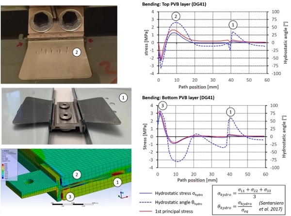
These observations correspond with the FE-analysis, that exhibits hydrostatic stress and hydrostatic angle maxima in the PVB (determined in analogy to Santarsiero 2017) at these points, also compare Fig. 10 in section 3.
Temperature impact
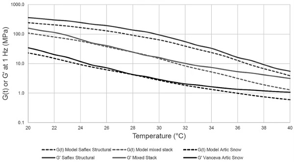
As the modular glass shell is a demonstrator object for indoor use on trade fairs and similar events, the current tests have all been made at room temperature. The data on the shear modulus of various interlayer compositions (Fig. 26) depending on temperature and on the surface adhesion provided by the manufacturer (Stevels 2022) show that increased indoor temperature up to 30 °C still provides high shear moduli especially for the pure structural PVB interlayer, which is the decisive material regarding the bond between the fitting and glass laminate. However, for outdoor applications or high temperature from direct solar radiation impact, relevant studies and tests on the laminated fitting connections yet must be made.
Such studies are of particular interest for long-term loads (e.g., self weight) at increased temperature and the related creep effects. Short term loads such as wind can be expected to have a low probability of occurrence at peak temperatures - an effect to be considered if qualifying particular load and temperature scenarios. While temperature variation constraint forces in the glass and the fittings have been shown to be relatively small in the global modular shell model owing to a certain flexibility of the local connections and the overall structure, the temperature impact on a laminated linear edge joint is more important, see section 4 below.
Test result impact on the modular shell design
With respect to the modular shell design, the test results allow the following statements:
- Structural glass fitting connection strength: The fitting connection provides more than sufficient strength for the connection loads determined in the glass shell demonstrator model. The maximum short-term axial tension design load in the connections from FEA is Nt,Ed = 5.5kN; the test results show failure levels above 30kN (glass failure) for the case of the stacked laminates from structural (DG41) and ordinary PVB (RB41). Please note that the shell modules are made from heat strengthened glass, whereas the test specimens were made from annealed glass. Thus, it can be assumed that the delamination failure from the tests with pure structural PVB at forces above 38kN would be applicable for the shell. For short-term bending, a maximum of MEd = 0.028kNm occurred in the shell joint model; the tests show min. bending strength levels of 0.07kNm to 0.08kNm in the elastic range (without fitting plastification). For shear, a maximum of VEd = 1.2kN in the shell joints from the FEM contrasts with minimum test results of 15kN (annealed glass failure). (Fig. 18)
- Safety concept: The tests show ductile behavior of the fitting connections. Even though the stacked laminate specimens failed in glass breakage due to the use of annealed glass, it can be assumed that delamination would be the governing failure scenario when using heat strengthened glass, as applied with the glass shell. This is underlined by the delamination failure in the pure DG41-pull tests. The fittings remain connected with the glass laminate after glass breakage or after delamination, as can be seen from the post-failure load tests. Thus, the fitting connection is providing redundancy. Both above aspects confirm the safety concept of the modular glass shell (compare section 1.2).
- Spring stiffness derivation for FEM: The test curves allow to determine an axial elastic tensile spring stiffness of ~30’000 N/mm derived from the linear part of the test curve (Fig. 27) for one fitting. It should, however, be checked if slip or tolerance effects occur in the connections, as visible in the test diagram. For in-plane shear, ~10’000 N/mm are calculated for one fitting.
- Summarizing, the modular glass shell concept and FE-analysis for the trade-fair application are confirmed and secured by the test results. The tests, however, are not intended to deliver characteristic values, but to provide a first confirmation of concept and sufficient safety and load margin. Results show that the fitting strength could even allow for larger glass structures and higher loads than encountered within the glass shell demonstrator, but further studies would be necessary to secure this. Further testing should cover the long-term behavior of the connections subjected to less favorable environmental conditions such as temperature, humidity, sunlight influence etc.
Fitting design parameter studies
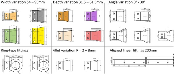
In addition to the studies of the fitting design implemented with the shell, parameter studies of the dovetail fitting geometry and of other fitting shapes have been made. These parameters and their variation are illustrated in Fig. 28. The width, the depth, the fillet and the trapezoid angle of the laminated metal sheet of the original dovetail fitting have been varied. In addition, a ring-like fitting sheet and a linear fitting have been analyzed. The total thickness of the interlayer (3mm and 4.6mm) and a loss of the edge bond (T-crossbar only works in compression contact) have also been studied.
Increasing the fitting width exhibits a nearly linear relationship between the applicable axial fitting load and the width parameter. Thus, this is an effective measure to increase the maximum load that can be transferred through the fitting, but at the price of increasing the fitting visibility. The peak stress in the connection, remarkably, is not reduced by increasing the width and the maximum load.
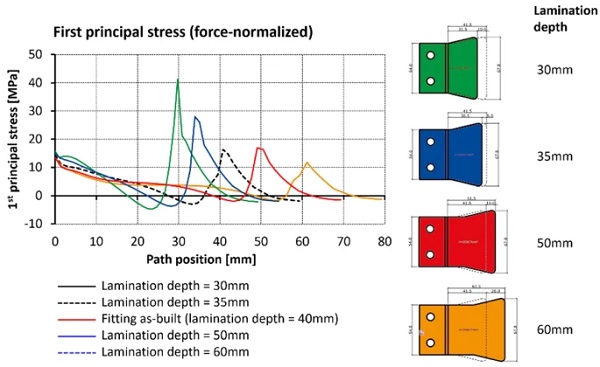
Increasing the fitting lamination depth (Fig. 29) permits only a non-linear, reduced increase of the applicable load on the fitting, but the peak stress in the structural PVB and in the glass in the vicinity of the boundary of the interior edge of the laminated dovetail reduces remarkably. However, more depth also means more optical visibility of the fitting, which may compromise esthetics.
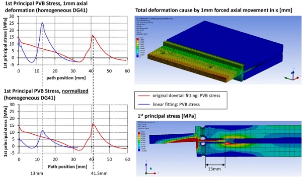
Owing to its reduced optical visibility and allowing for high transparency, linear fittings with minimal lamination depth represent an interesting alternative to the point-like dovetail fittings discussed above. To minimize temperature constraints along the edge, such fittings should consist of aligned linear parts with small expansion joints in-between (200mm per fitting have been chosen here). A lamination depth of 13mm has been used to correlate with a typical edge compound width of insulating glass units (Fig. 30). If compared to the dovetail fitting, not surprising, the edge bond of the linear fitting has a higher load transfer share (about 50–70% for short term loads) than the laminated part (Fig. 30). However, the load transfer share of the laminated fitting sheet increases with the loading duration.
Applying the same tensile deformation (1mm) to the dovetail fitting and the linear fitting causes higher stress in the PVB of the linear fitting compared to the dovetail solution because of the much higher stiffness of the linear fitting (Fig. 31). However, normalizing the stress results with respect to the force resulting from the fitting deformation reveals that the first principal stress in the PVB of linear fitting is actually lower than the stress in the PVB of the dovetail fitting (Fig. 31, bottom). The maximum principal PVB stress is also located at the interior boundary of the laminated metal sheet.
As for the bolt distances for the connection of glass modules via linear fittings, a bolt distance around 80mm along the fitting provided the best homogeneous stress distribution in the laminate and the bond. However, this topic has also to be evaluated comprising aspects such as temperature loads, tolerances and economic efficiency.
For the rigid, continuous linear edge fitting, temperature variation is an important load case to be considered regarding aspects such as delamination and stress peaks from different temperature behavior of the bonded materials. Apart from temperature increase, that comes with a reduction in the interlayer stiffness and can thus balance differential elongation of the bonded metal and glass components, especially cooling (temperature decrease) over a short period of time is to be considered. The latter case may cause increased constraint stress because of the high stiffness of the interlayer at low temperature. In addition, a potential increase of interlayer brittleness at low temperature has to be examined.
In any case it will be necessary to establish a linear structural connection by stringing metallic fittings of limited length (200mm length assumed in the FE parameter studies) along the edges to be joined. Thus, development of temperature constraints along the edge can be reduced. Construction wise, however, the lamination and joining tolerances of such a string of linear fitting pieces is challenging.
Conclusion and Outlook
The numerical parameter studies of the laminated dovetail fittings developed and applied with the modular glass demonstrator shell reveal the high potential of this structural glass connection bonded with structural PVB of the type DG41. The tests show a high tensile load strength of up to four tons and the realization of a reasonable joint bending stiffness about the glass edge by using a T-shaped crossbar bonded and force-couple supported against the glass edge. The tests also show a good ductility and post-breakage behavior of the fitting both in the case of glass failure and delamination. Thus, the use in modular glass shells is made possible with respect to safety / redundancy. At room temperature, creep from typical permanent tensile and bending joint loads determined for the case of the glass demonstrator shell is extremely small and does not compromise the structure. The lamination of a thin metal sheet into the interlayer zone of a laminated safety glass allows to work with thin glass build-ups from only two lites.
Future work to be undertaken for further laminated structural connection development comprises (a) the establishment of a FE-model adapted to the test boundary conditions, (b) examination of the fitting load bearing, creep and failure behavior in various temperature conditions, (c) optimization of the manufacturing process of the fitting itself and its lamination, (d) ductility, redundancy and safety aspect research and e() transparency increase / perceptibility reduction of the jointing. Linear fittings are of particular interest for laminated structural glass connections.
References - Link
Funding
Open access funding provided by Lucerne University of Applied Sciences and Arts. No funding was received by authors “a” and “b” to assist with the preparation / writing of this manuscript.
Author information
Authors and Affiliations
Lucerne University of Applied Sciences and Arts, Lucerne, Switzerland
Thiemo Fildhuth
Hochschule Luzern, Technik and Architektur, Technikumstrasse 21, 6048, Horw, Switzerland
Thiemo Fildhuth, Pascal Joos & Thomas Wüest
knippershelbig GmbH, Tuebinger Str. 12-16, 70178, Stuttgart, Germany
Thiemo Fildhuth
Lucerne University of Applied, Sciences and Arts, CC Building Envelopes and Civil Engineering, Lucerne, Switzerland
Pascal Joos & Thomas Wüest
Solutia Deutschland GmbH, Düsseldorf, Germany
Matthias Haller
Eastman Chemical bv, Watermanweg 70, Rotterdam, The Netherlands
Wim Stevels
Corresponding author
Correspondence to Thiemo Fildhuth.
Ethics declarations
Conflict of interest
On behalf of all authors, the corresponding author states that there is no conflict of interest. The fabrication of the modular glass shell mentioned above, the test specimens and the testing was funded by Eastman Chemical bv, The Netherlands, within a third party industry R&D-project. Co-authors “c” and “d” are affiliated with the above company as employees.
Additional information
Publisher's Note
Springer Nature remains neutral with regard to jurisdictional claims in published maps and institutional affiliations.