Article Information
- Digital Object Identifier (DOI): 10.47982/cgc.8.378
- This article is part of the Challenging Glass Conference Proceedings, Volume 8, 2022, Belis, Bos & Louter (Eds.)
- Published by Challenging Glass, on behalf of the author(s), at Stichting OpenAccess Platforms
- This article is licensed under a Creative Commons Attribution 4.0 International License (CC BY 4.0)
- Copyright © 2022 with the author(s)
Authors:
- Pietro Demontis - Arcora
- Julia Endress - Sika Services AG
- Viviana Nardini - Sika Services AG
- Arnaud Vernier - T/E/S/S

Abstract
Curved and free-form glass façades represent a clear trend in architectural design. Hot bending is the most common technique used to produce curved Insulating Glass Units (IGU). Although its effectiveness has been proved in many projects, it is well known that it can also be very expensive due to the big number of moulds usually required to build up a free-form façade. As alternative to the ‘hot-bending’ technique, the increasingly used ‘cold-bending’ method is investigated in this paper being less expensive as well as more sustainable. Such method consists in imposing an out-of-plane displacement to flat insulating glass units and generally requires forces of limited magnitude applied on site during installation.
Cold-bending introduces permanent loads into the glass panes, the glass interlayers, the secondary sealing as well as the primary sealing, the latter one responsible for the gas retention and the resistance to moisture penetration in the IGU cavity. The paper presents the results of FEM analysis as well as tests performed on double glazed units including Sikasil® IG-25 secondary sealing joints and SikaGlaze® IG-5 PIB as primary seal and investigates their behavior due to cold-bending and exposure to climate conditions in accordance with EN1279-2. The results show that appropriate FE analysis can well predict the behaviour of the cold-bent system and that the amount of out-of-plane displacement introduced in the IGUs does not affect their integrity and durability. As example, the cold-bent limit identified is applied for shaping a cold-bent IGUs façade in a high-rise building.
1. Introduction
Cold-bending is an economic method to produce curved glazed envelopes by using flat Insulating Glass Units (IGUs). Indeed, it allows to generate curved surfaces without using ‘hot bent’ glass panels, which require expensive moulds.
The easiest way to implement such technique on site usually consists in imposing an out-of-plane force to one corner of the flat IGU. Although many projects with complex shape and strong building identity have been already built in the last decade by exploiting such technique, limited guidelines are available to design cold-bent insulating glass units and to ensure their integrity and durability over the service life.
Focusing on the performance of the edge seal in cold-bent IGUs, this paper presents:
- Test results of double glazed units cold-bent and exposed to thermal cycles according to EN1279-2. Target of the tests is to evaluate how the vapor penetration varies from flat to cold-bent IGUs and to measure the shear displacements imposed to the secondary sealing joints due to cold-bending.
- Numerical results comparing FE analysis predictions with empirical results as well as calculations based on simplified equations.
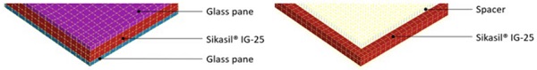
2. IGUs configuration
Double glass units 1200 mm x 1700 mm are used for the investigation. The units consist of a monolithic glass pane 8 mm thick on both inner and outer layer, spaced by an air cavity 24 mm deep. Chromatech Ultra F 24 is used as spacer, together with SikaGlaze® IG-5 PIB as primary seal and Sikasil® IG-25 as secondary sealing joint.
The glass units are retained by punctual fixations applied on three corners, as detailed in the following sections. Cold-bending of the units is performed imposing an out-of-plane displacement of 40 mm on the free corner.
3. Test rig for IGU cold-bending
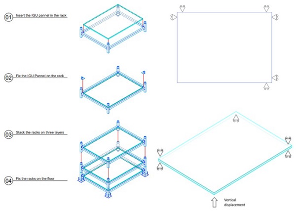
The tests described in the following sections are performed using a steel rig specifically designed to cold-bend three IG units 1200 mm x 1700 mm and to keep them deformed during the exposure to climate conditions in oven.
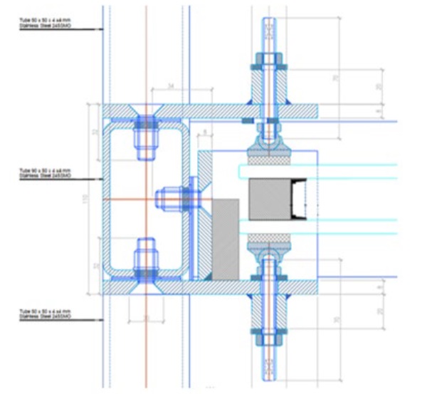
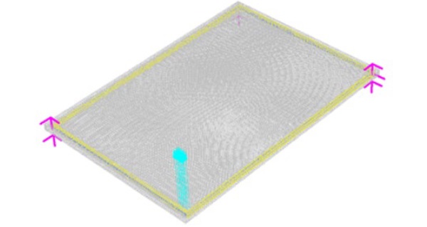
The rig consists of three steel frames that can be stacked one over the other (Fig. 1). The supporting conditions ensured for each IG unit in the frames are the following:
- The lower glass pane is blocked in horizontal directions by rigid setting blocks (i.e. in-plane movements are prevented).
- The upper glass pane is free to move in horizontal directions (i.e. in-plane movements are free)
- Three punctual fixations applied on three corners prevent vertical movements.
- One corner is free to move in vertical direction; on such corner a vertical force is applied to impose the cold-bending displacement.
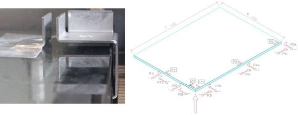
Fig. 1 provides also restraint details for the lower and upper glass panels of the IGUs in the rig. Fig. 2shows a detail of a punctual fixation retaining in vertical position the unit as well as the rigid setting block preventing the lower glass pane to move in its own plane.
4. Durability test according to EN1279-2
4.1. Test method
A key question always arising when designing cold-bent IG units is how to assess their durability performance over service-life. No standard provides answer to the question and no guidelines or recommendations exist to design and deal with cold-bent IG units.
EN 1279-2 describes a test method for the determination of the average moisture penetration index Iav and the moisture penetration index I for flat IGUs and specifies the requirements for limit values to demonstrate that components (edge seal or spacer) will allow the insulating glass units to conform to durability requirements.
The test method and requirements given by EN 1279-2 are here extended to evaluate the performance of the cold-bent units.
The following samples are produced for the tests:
- Sample set 1 – 15 x IG units 350 mm x 500 mm with glass composition 4 / 12 / 4 and Sikasil® IG-25 joints 10 mm wide
- Sample set 2 – 3 x IG units 1200 mm x 1700 mm with glass composition 8 / 24 / 8 and Sikasil® IG-25 joints 20 mm wide, to test in the flat state.
- Sample set 3 – 3 x IG units 1200 mm x 1700 mm with glass composition 8 / 24 / 8 and Sikasil® IG-25 joints 20 mm wide, to test in cold-bent shape under 40 mm out-of-plane displacement imposed at one corner.
All IGUs include Chromatech Ultra F 24 spacer and SikaGlaze® IG-5 PIB as primary seal.
Sample set 1 covers the regular sample configuration required by EN1279-2 to evaluate the adequacy of spacer, primary seal and secondary seal in IGU units in terms of long-term performance.
Sample set 2 is used as reference for comparing results in real-scale flat units to equivalent cold-bent units (sample set 3) as well as standard EN1279-2 samples (sample set 1).
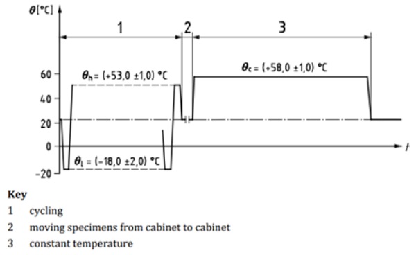
All samples are exposed to the following climate conditions (Fig. 3):
- Alternating climate test: 56 temperature cycles of 12 hours each (4 weeks) with temperatures of -18 °C and +53 °C with slopes of 14 °C/h. The relative humidity is 95% for the high temperature phases.
- Constant climate test: 1176 hours (7 weeks) exposure at 58 °C and > 95% r.h.
- Storage at standard climate: all samples stored for at least one week at 23 °C and 50% r.h.
The moisture content in bulk is determined according to EN 1279-2 Clause 7 and 540 °C dry method. The desiccant is removed from the spacer of the samples and subsequently dried in the oven at 540 °C for at least 120 minutes. After heat exposure the crucibles full of desiccant is taken from the furnace, closed up with a lid and placed into a dry desiccator. From the mass difference before and after drying, the moisture content of the units can be calculated.
For the IGUs of sample set 1, the initial and the final moisture content is determined before and after climate exposure on four and five samples respectively, according to EN1279-2 test procedure out of 15 samples. From the difference between initial and final moisture content, the moisture penetration index I and the average moisture penetration index IAv are calculated.
For the large IGUs of sample set 2 and sample set 3, only the final moisture content after climate exposure is determined and compared.
All tests were performed at an accredited Lab Institute (ift Rosenheim - Germany).
4.2. Test results
Sample set 1 covers the standard sample (small IGUs) configuration of EN 1279-2, that requires thefollowing:
- The average moisture penetration index IAv of five test specimens must not exceed 20%
- The moisture penetration index I of any test specimen must not exceed 25%.
The test results obtained for Sample set 1 satisfy the requirements:
IAv = 8.5 % < 20 % Average moisture penetration index
Imax = 13 % < 25 % Maximum value recorded as moisture penetration index
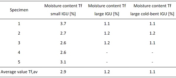
Table 1 compares the moisture penetration of sample set 1 (small IGU) with sample set 2 (large IGU) and sample set 3 (large IGU / bent), by comparing the final moisture content Tf and the final average moisture content Tf,av of the desiccant.
The results allow to conclude the following:
- Based on tests performed according to EN1279-2 samples (sample set 1), the system composed by Chromatech Ultra F 24 spacer, SikaGlaze® IG-5 PIB primary seal and Sikasil® IG-25 secondary sealing allows insulating glass units to conform to standard durability requirements. That means, any flat unit with different dimension and composition is considered to perform properly in terms of durability as long as spacer, primary seal and secondary seal used are the same.
- The final moisture content of desiccant for sample set 2 is lower than in sample Set 1. Although data about initial moisture content of desiccant is not available for sample set 2, it can be inferred that sample set 2 performs better as:
o Sikasil® IG-25 joints are bigger (20 mm in sample set 2 and 10 mm in sample set 1)
o The deformation experienced by the joints in sample set 1 is higher, as the internal overpressure related to the climate cycles is higher. Based on glass dimensions, IGU composition and production conditions, it is estimated that Sample set 1 experiences an internal overpressure approx. 6 times higher than in sample set 2.
- The final moisture content of desiccant in sample set 3 is lower than in sample set 2. Although data about initial moisture content of desiccant is not available, it can be concluded that the cold-bent deformation did not affect the durability performance of the units. The fact that moisture content is lower could be simply justified by tolerances.
With regard to durability performance, the test results prove that the IG units cold-bent at one corner by 40 mm have an equivalent behavior as flat IG units. It must be remarked that the results apply to IGUs cold- bent by imposing a displacement at one corner and mechanically retained in all corners (including the one where the cold-bending is applied). Different results could apply to IG units cold-bent but not mechanically retained, e.g. IG units that are structurally bonded to frame or IG units with the inner glass pane retained by toggles.
Table 1: Moisture content comparison.
5. Measuring differential shear displacements
5.1. Test method
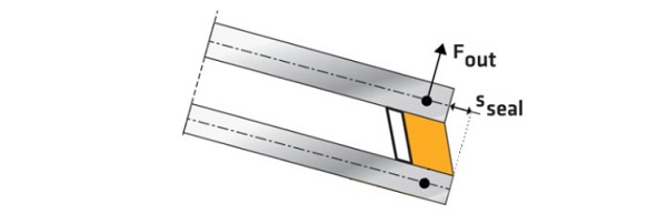
Cold-bending of IGUs causes differential shear displacements between the inner and outer glass panes, which impose shear deformations to the secondary sealing joints (Fig. 4). In Sections 6 and 7 simplified equations and FE analysis provide predictions of the expected deformations. The tests described in section 4 provide an opportunity to measure them.
To measure such differential displacements, aluminium brackets are fixed to the lower and upper glass panes in five different positions marked as Pos. 1 – Pos. 5 (Fig. 5).
The relative distance between the bracket applied on top and bottom panes is measured at different test stages. The whole test sequence can be described as follows:
- Fix the metal brackets in 5 different positions on the three IGUs 1200 mm x 1700 mm in the flat state
- Place the IG units into the test rig, in flat horizontal position
- Put the frame with the IGUs into the climatic chamber
- Measure the relative distance between the metal brackets applied at the bottom and upper glass panes in Pos. 1 – Pos. 5 (initial state with flat IGUs)
- Bend the IGUs, imposing 40 mm vertical displacement upward
- Measure the relative distance between the metal brackets applied at the bottom and upper glass panes in Pos. 1 – Pos. 5 (IGUs in cold-bent state)
- Start climate cycles according to EN 1279-2 without moving the units
- After climate cycles, reconditioning at 23 °C / 50 % r.h. for approx. 5 hours
- Measure the relative distance between the metal brackets applied at the bottom and upper panes in Pos. 1 – Pos. 5 (IGUs in cold-bent state)
- Release the IGUs from the vertical deformation imposed by cold-bending
- Store the IGUs for seven days at 23 °C / 50 % r.h.
- Measure the relative distance between the metal brackets applied on the bottom and upper panes in Pos. 1 – Pos. 5 (final state with flat IGUs)
After 4 weeks in the climate cycles (Step 7) a detachment of the metal brackets was observed. After fixing them again, the relative distance between the metal brackets applied at the bottom and upper panes in Pos. 1 – Pos. 5 was measured again. Unfortunately, such failure does not allow to compare the displacements recorded before and after the climate exposure.
The test uncertainty of the distance measurements is estimated taking into account the measurement uncertainty of the test equipment and the standard deviation of multiple measurements where applicable.
5.2. Test results
The visual inspection at the end of the test did not show any difference between the IG units that were bent and those that were not.
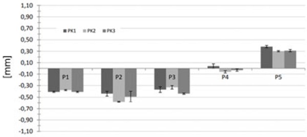
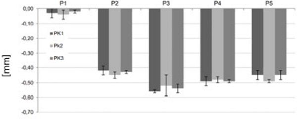
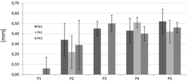
The differential shear displacements occurring due to cold-bending in k and l direction (Fig. 5) in Pos. 1 – Pos. 5 before climate exposure are shown in Fig. 6 and Fig. 7 respectively. The following can be observed:
- The maximum differential displacement occurring in the glass plane is approx. 0.6 mm.
- In general, the highest displacements are recorded near the corner where the displacement is imposed, in Pos. 2 and Pos. 3. This is consistent, as the higher rotation are expected here.
- The displacements values in Pos. 4 and Pos. 5 do not look consistent as:
o in l direction (Fig. 7) they have almost the same magnitude than in Pos. 2 and Pos. 3, while lower values would be expected.
o in k direction (Fig. 6) a sign change occurs, leading to inconsistent pane deformations.
More considerations about such unexpected behaviour are provided in Section 7.
Unfortunately, a statement about the differential displacements occurring during the climate exposure cannot be made as bracket detachment occurred after 4 weeks in the climate chamber.
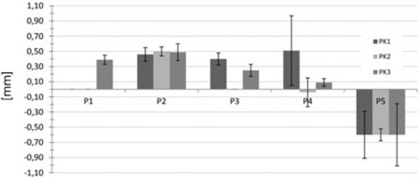
Fig. 8 and Fig. 9 provide the differential displacements measured after release of the vertical cold-bending force. The displacements have opposite direction than those occurring in Fig. 6 and Fig. 7, showing that they are relaxing back. The displacement magnitude is similar to those given in Fig. 6 and Fig. 7, proving that the units have flipped back almost to the initial flat state.
6. Shear displacements in the secondary sealing joint based on simplified equations
Cold-bending of an IG unit has two main effects on the secondary sealing joint:
- Imposing a permanent differential shear displacement sseal to the joint (Fig. 4)
The value sseal can be calculated as described in Nardini and Hilcken (2018):
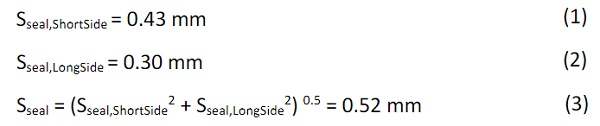
where:
Sseal,ShortSide = max. differential shear displacement in the direction of the short IGU side
Sseal,LongSide = max. differential shear displacement in the direction of the long IGU side
Sseal = total differential shear displacement
The shear displacement sseal produces a shear stress in the joint:
![]()
With:
G = 0.73 MPa Shear modulus of Sikasil® IG-25
e = 24 mm Joint thickness
The following relationship is satisfied:
![]()
With:
τRelax = 0.03 MPa Sikasil® IG-25 permanent shear strength accounting for relaxation.
- Transferring permanent tensile stress to the joint, due to the force Fout (Fig. 4) caused by the outer glass pane that wants to flip back in flat position. Such stress applies to the joints if the outer pane is not retained mechanically and can be calculated as follows, as described in Nardini and Hilcken (2018):
![]()
Where:
Fout = 120 N
W = 1200 mm glass width
H = 1700 mm glass height
b = 20 mm joint bite
The following relationship is satisfied:
![]()
with
σStat = 0.014 MPa Sikasil® IG-25 permanent tensile strength.
With reference to the long-term performance of the joint, the following relationship is satisfied:
![]()
It must be noticed that in the performed tests the outer pane of the cold-bent IGUs is always mechanically fixed. Consequently, it can be assumed that in the long-term σ = 0 MPa and μ = 0.53.
In the short-term, the utilization level of the joint should be calculated also considering the effects of climatic loads. For the system and loads involved, the short-term condition is less critical and details of the analysis are not provided here.
7. Shear displacements in the secondary sealing joint based on FE method
The behaviour of the cold-bent insulating glass unit is simulated by FE method using the software Strand 7. Geometrical non-linear analysis is performed to evaluate the mechanical performance of the secondary sealing joints.
In order to understand the most appropriate way to model the spacer and the aluminium shims that hold the lower glass panes in position, a preliminary sensitivity analysis is carried out evaluating three different FE models.
FE model A
The IGU components are simulated as follows:
- Sikasil® IG-25 silicone joints are simulated by hyperelastic material law according to data provided by Sika. Two Hexa20 brick elements (quadratic volume elements) are used over the joint thickness (Fig 10) according to Sika FEM guidelines.
- The monolithic glass panes are simulated by Hexa20 brick elements
- The spacer is simulated by cut off bar elements released in rotations.
The restraint conditions represent the cold-bent IGUs in the test rig (Section 3):
- The lower pane is blocked for translations in the horizontal plane (i.e. glass plane) and is free to move vertically in the cold-bent corner
- The upper pane is free to move in the horizontal plane (i.e. glass plane)
- The vertical bolts keeping the IGU in position are modelled as cut off bar.
Fig. 11 shows the FE model with the restraints and the cold-bending force applied at one corner.
FE Model B
As Model A, but the aluminum shims are simulated as point contact bars, having real dimensions and rigidity. The lower glass pane is restrained by these elements. The spacer is simulated by cut off bar elements.
FE Model C
As Model B, but the elements representing the spacer are removed.
Fig. 12 superposes the horizontal differential displacements of the upper and lower glass panes for model A, B and C and shows that the difference in displacements between each model is very low, ranging from 0.2% to 10.2% with an average value of 2.8%.
Such differences are not considered significant and Model A is used as reference for further analysis.
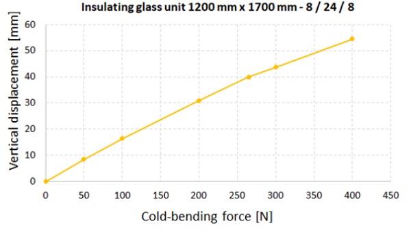
The magnitude of the vertical displacement of the free corner depends on the magnitude of the out of plane force applied. In order to have a cold bending process that can be easily implemented on site during the construction phase, a force magnitude varying from 0 N up to 400N is considered.
The relationship between cold-bending force and vertical displacement is plotted in Fig. 13 and appears almost linear. Such behaviour can be explained by the fact that the range of vertical displacements here investigated is relatively small and Sikasil® IG-25 adhesive works in a small deformation range, so that its material law could be simplified as linear.
The graph shows that a force of approx. 400 N is required to achieve a vertical displacement close to 55mm, while a force of approx. 265 N applies for a vertical displacement of 40 mm.
For an IG unit 1200 mm x 1700 mm, a displacement of 40 mm means:
- a radius of approx. 27 m;
- a warping equal to d / 52, where d is the diagonal of the IGU which is cold-bent
It is interesting to point out that based on state-of-the-art, the maximum warping accepted in France by certification bodies is d / 200 (d = diagonal of the glass unit), when no specific investigations are performed. This limit is mainly set due to the tolerances in the fabrication and construction phases of the supporting structure.
IGU manufacturers in Europe usually recommend limiting the vertical displacement due to cold-bending to maximum d /100.
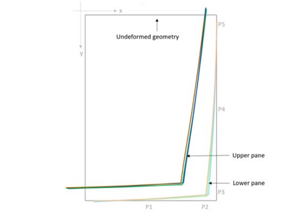
The FEM analysis allows also to estimate the differential shear displacements occurring between upper and lower glass panes in Pos. 1 – Pos. 5. Fig. 14 (left) shows the physical interpretation of the results, with reference to a cold-bending force of 265 N (producing the out-of-plane displacement of 40 mm). At first, we draw the horizontal projection of the sides of the panes by interpolating the displacements given in Pos. P1 – Pos. P5.
Then these projections are superposed to the undeformed geometry of the IGU. By applying an upward out of plane force on the lower pane and considering that the lower pane is fully blocked for the horizontal translations, the upper pane starts sliding backward while the secondary sealing joint deforms in shear in both horizontal directions. These results confirm the behaviour we can intuitively expect for the cold bent IGUs.
The FE analysis predicts that a maximum shear displacement sseal of 0.52 mm is imposed to the joint due to the 40 mm cold-bending.
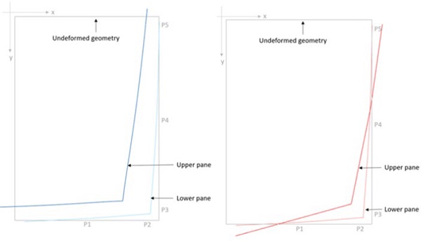
The numerical results obtained by FEM can be compared to the tests results in Section 5.2 and Fig. 14 (right). The comparison highlights there is a big difference in terms of displacements: in Pos. 1, Pos. 4 and Pos. 5 a divergence is observed with the upper glass pane in the tests moving in opposite direction compared to FEM. In addition, the displacements dx measured in the test have opposite direction in Pos. 4 and Pos. 5 leading to a non-realistic deformation of the upper pane.
Following additional internal tests not included in this paper, we believe that the test measurements for the differential shear displacements are not fully reliable as affected by intrinsic errors. Although the test displacements have an order of magnitude of 0.1 – 1.0 mm and are measured by a caliberhaving a precision of 0.01 mm, the following considerations apply:
- The measurement of the differential displacements between the brackets fixed to upper and lower glass pane (Fig. 5) is affected by the stiffness of the brackets and their connection to the panes. In other words, it is easy to measure a displacement 0.x mm greater or smaller than the real one, just due to a minimal pressure imposed to the bracket during operations.
- Gaps in the order of 0.x mm between the lower glass pane and the shims blocking it in-plane can cause uncontrolled rotations of the lower glass pane. Such rotations can pollute the final measurements, which have the same order of magnitude of such possible gaps. Indeed, the aluminum shims to block the lower glass panes are placed after the IGUs are installed in the rig. To insert such shims, some tolerances bigger than 0.1 mm must exist.
For a better understanding of the shear displacements imposed to the secondary sealing joints of cold-bent IGUs, a deeper investigation is required to:
- Assess the effective stiffness of edge seal systems in terms of composite behaviour of secondary sealing, primary seal and spacer, to implement them properly in FE simulations. As example, adhesion of the secondary seal adhesive to IG spacer must be always ensured in production but it is always neglected in FE calculations.
- Measure with greater accuracy the differential shear displacements occurring between glass panes of cold-bent IG units.
On the other hand, the shear displacement sseal = 0.54 mm predicted by FEM matches very well the result sseal = 0.52 mm obtained by simplified equations (Section 6).
8. Conclusions
No standards exist to evaluate the durability performance of cold-bent IGUs. In section 4, an extension of the test method given by EN1279-2 is proposed to evaluate it, referring to moisture penetration measurements. The test results show that the durability performance of the tested IGU is not significantly affected by cold-bending. This can be stated only with specific reference to:
- The edge sealing system tested, which includes Chromatech Ultra F 24 as spacer, SikaGlaze® IG-5 PIB as primary seal and Sikasil® IG-25 as secondary sealing adhesive.
- IGUs mechanically fixed at all corners and cold-bent by imposing an out-of-plane displacement at one corner. More in detail, the outer glass pane is retained mechanically according to a layout and stress condition totally different than in IGUs bonded to frame or with the inner glass pane retained by toggles.
- A cold-bending deformation equivalent to d / 52.
As a concept, the test method proposed could be used to assess the durability performance of any other cold-bent IGU, which either includes a different edge sealing system or has a different cold-bent configuration, restraints conditions or deformation level. Additional measurements related to the initial moisture content of desiccant could allow to collect more comprehensive data, despite IGU costs.
Simplified equations allow to predict a maximum differential displacement of sseal = 0.52 mm occurring between top and bottom glass at the cold-bent corner, due to 40 mm cold-bending (d/52). Such value is very close to the value of 0,60 mm measured during the tests. On the other hand, the overall reliability of the test measures is very uncertain as the different measures recorded in Pos. 1 – Pos. 5 for the cold-bent units do not seem consistent. FE analyses predict a maximum value of sseal = 0.54 mm, matching very well the results obtained by simplified equations.
The success of the durability tests proofs that it is possible to design IGUs retained mechanically and cold-bent at one corner having a warping up to d / 52, outside typical limits. Of course, the results must not be uncoupled to the specific edge sealing system and joint dimensions used and by the fact that monolithic glass panes are used in this investigation rather than laminated glass (where delamination might occur).
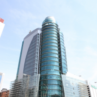
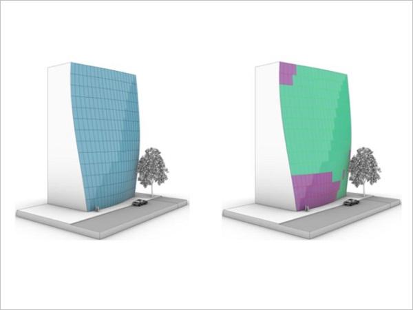
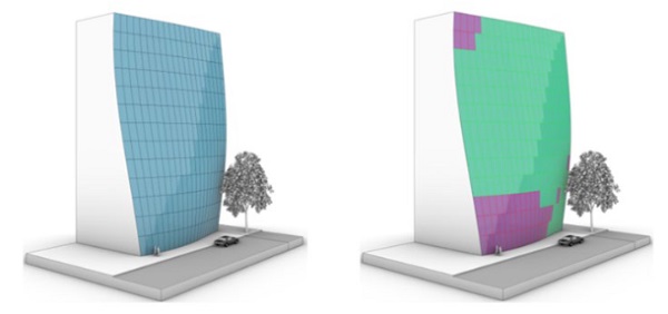
The application of the cold-bending limit identified in this investigation could introduce new opportunities in the design of insulating glass facades, as shown in the example of Fig. 15 for a high rise building. On the left side we can appreciate the high degree of curvature introduced in the façade; on the right side we mark in green the IGUs that are cold-bent according to the maximum limit criteria of d/52 and in violet the few IGUs with curvature slightly exceeding such limit.
Acknowledgements
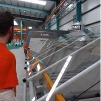
The authors thank Polypane and Kutas-Erdem for supplying the insulating glass units used in the tests and additional ones used for preliminary investigation.
References
Nardini V., Doebbel F.: Structural silicone joints in cold-bent SSG units, GPD 2017
Nardini V., Hilcken J.: Mistral Tower: value of system design, manufacturing and installation in cold-bent SSG units, Challenging Glass Conference 6, 2018.
Test report 19-002389-PR01 (PB-H01-09-en-01), long-term aging behavior of insulating glass units based on DIN EN 1279-2 for small IGUs (352 mm x 502 mm) and large IGU (1200 mm x 1700 mm), ift Rosenheim, 2019.
Sikasil® SG joint calculation – Additional technical information for computer-aided analysis to simulate the joint behaviour in façade applications using Sikasil® SG adhesives, 2017.