![[1] An Engineer Imagines, Peter Rice](/sites/default/files/inline-images/01_1.jpg)
When I first met Sophie Pennetier, I was struck by her expressed influences and her remarkable experiential pedigree. She cites Peter Rice’s brilliant book, An Engineer Imagines, as the inspiration for her engineering pursuits (a source of inspiration we share) [1]. She describes herself as balanced between industrial design, architecture and engineering, a balance that I’ve long recognized as the sweet spot.
She interned with Hugh Dutton’s specialty group and Rice’s famous Paris firm RFR (Rice, Francis & Ritchie) early on. I’d have given my eye teeth for that opportunity. And she has gone on to work with leading international firms including Arup, Guy Nordenson and Associates, and SHoP Construction in New York. In a consulting role she has worked with many prominent architects, including Diller Scofidio + Renfro (DSR), BIG, SHoP, Fosters + Partners, Stanton Williams, on a number of landmark projects, some few of which she discusses following. Infinitely curious, Sophie is now working on the “build” side with national façade contractor Enclos in their Advanced Technology Studio located in Los Angeles.
We also share a long term and deep fascination with glass.
So, what is it about glass that you find so compelling?
Glass is the ultimate material: it is strong like steel, flexible like aluminum, and quasi transparent. It’s a complex material to detail, unforgiving since it doesn’t have the plasticity of construction metals, but very rewarding for anyone interested in Specialty Structures. Today I am looking into ultra-thin glass, a paper-thin material currently used for interior wall panels and some flexible electronics applications. I think it has a lot of potential in our industry. While researching the material I applied for a grant with Urban Glass Brooklyn in 2016 and was awarded a fellowship from the Metropolitan Contemporary Glass Group, and an “Invest in Arup” research budget. I reconciled my art and engineering minds through a sculptural exploration using this material.
Transparency, both literal and figurative, has a long history in architecture. What role does transparency play in your work?
![[2] Bistro de l’Arche, Paris](/sites/default/files/inline-images/02_3.jpg)
There is transparent and invisible. “The invisible architect” by Marvin Mass, landed in my hands around 2014 or so. Marvin Mass is the founder of Cosentini Associates and a key figure in the field of building mechanical engineering.
We tend to forget and sometimes devalue what we cannot see, or do not know how to see. Design process is invisible; glass is almost invisible. My first built design was a steel and glass box in Paris, with lighting, louvers mechanism, and gutters hidden within the thin steel beams [2].
![[3] Ultra-thin glass sculpture](/sites/default/files/inline-images/03_2.jpg)
My first ultra-thin glass sculpture was a challenge to photograph because it tended to disappear as an image! This can be an attribute in an architectural feature, but something of a dilemma in sculpture. [3]
And then there’s transparency of expression; a clear design strategy, a load path expressed as a diagram of force, an exposed steel structure (AESS), the embodied carbon of the jewel boxes we design.
![[4] Full Moon Theatre](/sites/default/files/inline-images/04_2.jpg)
Transparency to the visible light spectrum as with extra-clear glass, or instead, harvesting the light like Peter Rice’s Full Moon theater mirrors [4], or twisting the light like the work of our friend Philip Bompas with Mark Pauly et al. [5] The thermal and acoustical transparency of our facades and structures is also an area of consideration.
![[5] Caustic lens (Pauly, Bompas et al.)](/sites/default/files/inline-images/05_0.jpg)
Tell us about a few of your many major contributions to the field of specialty facades and structures. What are your personal favorites?
For over a dozen years now, I have had the opportunity to work as a structural engineer on the steel structures of iconic architectural projects, exploring the numerical analysis of structural glass, cold bent glass and the structural use of ultra-thin glass. Simultaneously, I have been lecturing at multiple universities and international conferences, engaged in various societies, committees, editorial and advisory boards.
![[6] US Olympic and Paralympic Museum](/sites/default/files/inline-images/06_1.jpg)
Some of the most exciting and personally rewarding work has been with Diller Scofidio + Renfro (DSR). I was lucky to join Dan Brodkin’s group at Arup in 2015, who has been collaborating with DSR for many years now. It was truly inspiring to be sucked up in this synergy and take a pivotal role in it. The first of three DSR projects I worked was the US Olympic and Paralympic Museum (USOPM) [6].
The building architecture revolves around a set of spiraling gallery floors spanning between four central cores and four spiraling facades trusses.
![[7] Broad Museum](/sites/default/files/inline-images/07_0.jpg)
Each truss is supported on the ground on one end and on the adjacent truss on the other end, creating these lifting moments where the structure is expected to disappear — a design feature that is characteristic of DSR’s architecture. You can see this here in Los Angeles at the Broad Museum [7]. These lifting and peeling off moments allow for natural light to flow into the building.
Tell us more about your design intent.
The acute clarity of a structural load path is a design philosophy essential to specialty structures and façades and to a greater extent, to glass: It refers to so called “positive load path” and “isostatic” systems. Isostatic systems, to put it simply, are systems that can be compromised by the suppression of one member. A three-legged stool is isostatic. If you remove one leg, the stool falls over. If you add one more leg, it is “hyperstatic” which means it is over constrained: you don’t really know which of the three longest legs take the load, and if they are all exactly the same length, the load distribution depends on relative stiffness.
![[8] Le Nuage de l’Arche, Paris](/sites/default/files/inline-images/08_0.jpg)
A load path that depends on stiffness is a challenge for fabricated structures, where more material attracts more loads and results in need for more material… (ref. “Don’t Design with Your Heart” by Omer W. Blodgett). Truth is, complex systems are rarely independent of stiffness distribution, it is unavoidable to an extent. However, hyperstatic systems essentially rely on stiffness, and it is sometimes impossible for the engineer to predict the exact load path under every single load (ref. Nuage the l’Arche de la Defense [8]). A “positive” load path is making sure you have at least one viable solution of a system.
Describe some examples.
At the roof of the Olympic Museum, I sized kinked beams to minimize the visual impact of the structure through the short vertical clerestory windows. Beams kinks and web stiffeners result in a complex load and stiffness distribution that requires advanced finite element analysis. A kinked beam is visually preferable to a straight beam with a stub, the beam is still in the light, you rather want a beam of light…
![[9] Alice Tully Hall, Juilliard School](/sites/default/files/inline-images/09_0.jpg)
Another dramatic lift-corner moment I designed in its early stages is the South East corner of Concert Hall of the Tianjin Juilliard School of Music. It is very much the same concept as in the New York Juilliard School of Music building (Alice Tully Hall [9]) where the corner façade is hung from large overhead trusses, and the load of the floors above is carried out by offset slanted columns.
The gesture is the same on the atria of the new Columbia Business School buildings, another project in which DSR were the design architects. Of course, I fully credit the final execution design teams; my contribution was, in most projects, focused on early design development phase (DD) and essential to the eventual outcome, but much work remained to bring the concept to realization.
Being at the frontier between trades has been characteristic of my professional practice. Translating the architectural intent into viable structural solutions, coordinating their validity from a multi-disciplinary standpoint, seeking cross-project solutions or cross-industry techniques to disrupt our practice; this is the art of design, as I see it. It represents a role “beyond engineering,” one of strategy and advocacy.
Your experience bridges architecture and engineering. Tell us about that.
![[10] NAICM Aerial view © Pardo /AFP](/sites/default/files/inline-images/10_2.jpg)
For most of my career I have worked in practices comprised of architects and engineers, and as a result tapped into both fields to bring a hybrid response to project requirements. For instance, knowledge of 3D modeling software has proven critical for coordination, rationalization, estimating, structural finite element analysis pre- and post-processing, parametric design, and documentation. Projects such as the Olympic Museum or the Mexico City Airport (NAICM) would be challenging without a 3D modeling environment [10].
As a matter of fact, I often had to “hack” resisting two-dimensional workflows. On NAICM for instance, I served as a cornerstone between the above and below grade teams and developed a routine to transfer the ever evolving geometrical and structural information into a soil structure interaction software environment: Plaxis. Without diving into deep (geotechnical) detail, the nature of the soil under the airport is highly sensitive to the amplitude of loading, the depth of the basement excavation, and the curved contour of the Terminal’s raft, a stretched “X” of varying elevations. I was able to set up an iterative export process to update the model at regular design intervals, which greatly facilitated project workflows.
![[11] NAICM baseplate design parametric tool (3-dimentional capacity envelopes)](/sites/default/files/inline-images/11_1.jpg)
On the same project, I set up a scripted routine to automate the baseplate design of approx. 4,000 touch-downs of the steel structure of the terminal buildings on the basement concrete raft [11]. The tool I scripted in a SQL database environment and Rhino+Grassehopper interface served to automatically design, assign, locate, radially orient, detect clashes with adjacent structures, and draw the baseplates for over 55,000 combination entries.
The typical approach for large projects is to use a “one size fits all” method with a custom catalog of very few baseplate types. This wasn’t an option on NAICM: the design needed to be optimized for multi-directional high seismic loads, a radial structural grid network laid out by the architects, large variations of the raft elevation which required the incorporation of clash detection. If any of these clash detection iterations resulted in a baseplate change, the script would verify it again for each load combination.
Why was this important?
Typically, a set of constant values threshold is a simple way to assign a baseplate type. Here a threshold approach would result in significant oversizing which is an area of concern in seismic design because overdesigned baseplates can attract more loads (Omer W. Blodgett here again) and could also result in significant cost and time impacts in the construction.
This was extremely helpful to address combined multidirectional concomitant demands: while we often use non concomitant load envelopes in design for simplicity, they can not only result in overdesign, as mentioned above, but could in certain case be unconservative. In my script I created a custom 3D capacity boundary geometry for each element type, in which the data points are projected and automatically iterated until the governing limit state geometry is found, which resolves into the baseplate assignment. I also developed my script to generate 3D files for our structural coordination and documentation environment (Revit).
This is fascinating stuff. What are you up to now?
Nowadays with Enclos, I use the very same 3D modeling and parametric design environment in the facades industry. I cannot disclose much here about the projects I have been on for the past couple years, mostly in sales and design assist phases, but it’s been along the same thread of non-conventional materials, systems or geometry.
![[12] Web based glass design tool (3-dimentional glass makeup capacity)](/sites/default/files/inline-images/12_1.jpg)
For instance, we use 3D parametric modeling for takeoffs, estimating and design, such as detecting multiple instances of a same panel across a façade, geometrical rationalization etc.
We also use it for the development of construction means and methods procedures. I recently developed a glass design tool like the one for my baseplates: it uses the same approach of projecting demands onto capacity free-form surfaces of multiple glass configurations, in the context of the ASTM E1300 Standard Practice for Determining Load Resistance of Glass in Buildings [12].
Do you use any of this rather arcane stuff in your art practice?
I actually do! The geometry of my first ultra-thin glass sculpture, in 2017, consists in spiraling strips of glass, connected to form a reciprocal corrugated structure. The sculpture leveraged the cold bent glass research I delved in back in Europe.
![[13] Sculpture prototype (taped laser cut plastic)](/sites/default/files/inline-images/13_0.jpg)
At the time, I performed transient analysis of cold bent and warm bent laminates. As the thicker laminates resulted in high forces, I have since investigated thinner systems and techniques and used geometry at my advantage.
Starting with paper and plastic models, I developed structural concepts: developable geometry, reciprocal isostatic systems, hinge connections, etc. [13] I then used Grasshopper to generate the geometry and preprocess my finite element analysis. Since the paper-thin glass is cold bent, I needed to model the internal cold bending forces of each piece before they connected and shared the load across.
![[14] Sculpture finite element analysis concept](/sites/default/files/inline-images/14_0.jpg)
The imposed displacement in the bending stage is defined by a start and end point before the panel nodes are merged and that is where a parametric tool is essential [14].
In buildings, the glass elements are bent, and the superstructure supports the glass. In my sculpture bent panels support bent panels, each one has its own loading history, and each one supports each other to the extent of its capacity. There is a lot to be learned from a group of glass strips!
There’s a lot of talk in the industry about innovation. As someone who embraces the interdisciplinary side of our industry, what does innovation mean to you?
There is considerable innovation in our niche of special structures and facades, with novel designs, advancement of materials, cross-industry technology transfer; you know that from your work with ASI! But the true innovation is in re-thinking the whole paradigm: this field is going to be less and less lead by the mechanics of materials and fabrication. The real innovation lies in the integration of crucial considerations such as the life cycle of our systems, the upcycling of existing elements, embodied carbon reduction, waste reduction, extending the service life and enhancing the adaptability of buildings and their façade systems.
This is really an exciting time: you not only work for cool (inspiring architecture, human experience) you are working for the social good, not in a few projects but in every single project.
I know that you are very supportive of and engaged with our community. Tell us about some of that.
I try to balance the time I dedicate here between committee work and mentorship. Being part of the ASTM E06.52 committee in charge of the ASTM E1300 Standard Practice for Determining Load Resistance of Glass in Buildings, I have brought European references and case studies, engaged in US-European normative workshops, and supported the development of the first structural glass design standard for the US (WK37764).
I am also part of editorial boards and societies (Facades Tectonics Institute: Special Advisory Council, ASCE Architectural Engineering Institute: journal and curtainwall subcommittee, Society of Glass Technology, etc.). The most rewarding was probably coaching the master’s thesis of a USC student on ultra-thin glass in 2018/19, Josephine Stoddard: a talented, hardworking young woman, now soaring in New York.
As a woman engineer in the AEC industry you are in a pretty small minority. How does that play out for you?
At the same time funny and complex: I will always remember my first field inspections, in 2008. Men could not fathom that my female colleague and I can be anything else than either admin or client. They thought we were lost from some office job. Workers would be stunned when I would start pointing at eccentric concrete anchors or question a cable structure post-tensioning sequence.
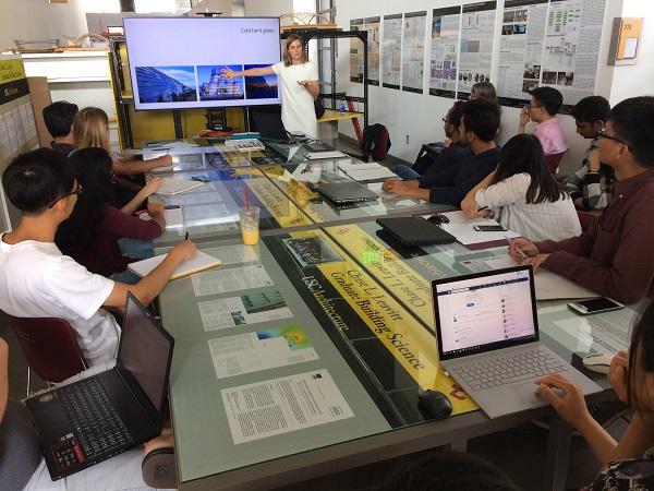
![[15] USC lecture (2017)](/sites/default/files/inline-images/15_0.jpg)
The construction industry is not the easiest environment for a woman engineer. I have been lucky to be embraced in the specialty structures and facades niche, but am often reminded that, from consulting to contracting, from the office to the site, there is much room for improvement in the attitudes towards women in the industry.
I have tried to engage more women to join the field by teaching at universities [15] and online, participating at international conferences [16], and representing women in industry discussion panels, sharing my experience to provide visibility and perspective to students and young workers.
![[16] GPD conference (2019)](/sites/default/files/inline-images/16_0.jpg) Hopefully, we can join forces to grow a field where we are all encouraged and fully empowered as equals. Women bring a different perspective, a different sensibility to the job. Increased diversity in the workforce will definitely benefit our industry.
Hopefully, we can join forces to grow a field where we are all encouraged and fully empowered as equals. Women bring a different perspective, a different sensibility to the job. Increased diversity in the workforce will definitely benefit our industry.