
Date: 11 June 2020
The ASTM E1300 Standard Practice for Determining Load Resistance of Glass in Buildings lays out procedures to determine the load resistance (LR) of specified glass types, including combinations of glass types used in a sealed insulating glass unit (IGU), exposed to a uniform lateral load of short or long duration, for a specified probability of breakage. It applies to either vertical and sloped glazing in buildings for which the specified design loads consist of wind load, snow load and self-weight with a total combined magnitude less than or equal to 15 kPa (315 psf).
The 62-page standard includes 88 charts and tables from which the designer derives the non-factored loads (NFL) in function of multiple parameters such as the glass thickness, panel size, boundary conditions, probability of breakage depending on whether the glass is used in an overhead configuration, short- and long-term duration of a load when applicable (Fig.1).

These charts are complemented by tables to determine the glass type factors (GTF) in function of the type of glass (annealed, heat-strengthened, fully tempered), or assembly (monolithic, double or triple pane IGU) in order to determine the load resistance of the glass elements. Further charts are used to determine the deflection of the glass lites, a function of load, thickness, panel size and boundary conditions. In buildings, service deflections typically govern the sizing of glass elements, rather than load resistance.
The designer draws glass design parameters from the charts, in both the figural and literal sense of the term, as illustrated in Fig. 1. This manual approach can be lengthy, prone to errors, and has a limited level of accuracy. Design is an inherently iterative process, and in this case can result in significant back and forth between charts and tables, while the procedure needs reset at each iteration. Namely, if one thickness of glass exceeds its design criteria for a given panel size, load and boundary conditions, the designer will select a new glass thickness and restart his evaluation from scratch with another chart.
For the above-mentioned reasons, the designers typically rely on approved commercial software packages for the immediate evaluation of the glass elements and prompt update of the thickness as needed.
These charts have been developed for analogic use, which is handy for in-person meetings. However, a digital tool is much more practical for iterative design. Professionals of our industry will not always have design tools at their fingertip (or designers, for that matter) in workshops, client/site meetings, etc. The web-based parametric tool discussed here allows practitioners to quickly (on the spot) assess the adequate glass components buildup, which will be subsequently submitted to the Structural Engineer of Record for review and stamp. This information can be used for quick estimating, construction means and methods, or a first pass of detailing. Meanwhile, a parametric tool is essential for “optioneering” which consists in developing a dynamic framework for analysis.
Being a member of the ASTM E06.52 Committee in charge of the development of the E1300 standard since 2013, I have been actively contributing to the elaboration of a draft for the first ASTM standard on structural glass design. In 2013, I developed an in-house parametric tool concept for use within the Rhino Grasshopper environment. The version discussed here expands on the original idea and applies to multiple configurations detailed below.
The essence of the tool resides in the fact that the E1300 charts contours represent the isolines of 3D design surfaces. These design surfaces (88 in total) correspond to multiple configurations of glass thicknesses, compound states (monolithic, laminated) and boundary conditions (1,2,3,4- side supported). Upon input of the size and load parameters and boundary conditions, the vertex representing the input parameters on a 2D plane is projected onto the design surface. The resulting elevation of the point projection gives the non-factored load (NFL) used to compute the load resistance of the glass compound. The process is similar for the determination of service deflections.
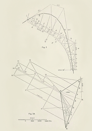
This approach of using 3D geometry to assess the capacity of an element draws from the concepts of graphic statics. Developed in the 1860’s, this historical method consists in geometrically resolving the equilibrium of 2D vectors representing the static forces on a 2D structure. The designer only needs paper, pen, ruler, and protractor. This can be extrapolated in 3D and significantly aided my computation.
This elegant vectoral method is yet exclusive of further modern (read: numerical finite approximation) fields of structural analysis, such as nonlinear analysis (as the term also suggests), dynamic relaxation and form finding, which require advanced software packages that already cover the scope addressed by graphic statics. The point here is that knowledge of the history of our field is far from narrowly preconditioning our approach to our trade, it is the loam for fertile innovation, and a bonus for truss design on a deserted island and/or any post-apocalyptic situation.
Although the present tool does employ vectoral resolution, it still consists in nodding out the demand and capacity in 3D. I had previously used this approach for a baseplate design script on the Mexico City Airport project with Arup, where I used the projection of large set of data points reflecting for each instance a particular combination of column location, local and global orientation, and non-symmetric concomitant load combinations into a series of 3D capacity envelopes representing the combined limit states of steel and concrete components of a large catalog of baseplates, in the delightful form of stretched concentric table spins envelopes.
This complex three-dimensional geometry approach was much more optimal than a threshold limit state approach (corresponding to a boring cube) which would result in overdesign of biaxial and non-concomitant loads. It can be broadly compared with Tresca versus Von Mises stress envelope contours. Furthermore, the geometrical approach is not just for ease of visual representation, it more importantly allows for the simple or intuitive handling of complex surface, which the designer non longer needs to define in a not so friendly polynomial equation.
For instance, in the case of the E1300 tool, first the isocurves were ‘drawn’ over the charts and lifted at the elevation representing the capacity (in the case of the NFL charts). Then, the domain in between was obtained by the creation of a NURBS surface generated from the isocurves control points. Lastly, the extrapolation beyond the isocurves (such as in the upper right of the NFL graphs, see Fig.1) was obtained by manual adjustment of select control points along the domain boundary. The degree and conditions of continuity at control points and all the complex polynomial equations of a NURBS surface remains behind the scenes and allows for a relatively clean script.
Based on this original idea and for the tedious (one time only) manual work of ‘drawing’ over the pixelated graphs, I paired up with my colleague Adnan Solanki who interned with us last semester to significantly grow the data set for the tool, from the typically 4-sided support condition to alternate configurations documented in the ASTM E1300: 1,2,3 side supports, monolithic, laminated, double pane, triple pane IGUs. The 3D modeling software we used (Rhino) has some limited tools to extract control points from pixelated rastered images, which accelerated our process.
The method however applies to any data source, vector graphics or numerical points cloud data sets. These alternate sources would allow for a much simpler preprocessing: bypassing the analog handling of the data which had been simplified already by the original E1300 authors for its integration to the “user-friendly” charts of the standard in the first hand, and re-interpreted from the rastered images by any user of the standard on the other hand, both within its original intent for the use of the ‘paper’ charts or for the production of our tool.
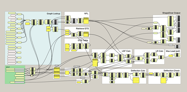
The design surfaces were generated in Rhino and internalized in Grasshopper, which are environments where we can develop and maintain the tool, but also connect it to other modules of parametric design. As alluted to earlier, I have subsequently transposed this work into a web-based, license-free, open-source, multi-platform environment for my team’s use. Keen on sharing knowledge across our industry, I also posted a pilot which can be found here:
https://app.shapediver.com/m/e1300-glass-design-tool
ShapeDiver is a web-based platform allowing the non-parametric-savvy professionals to visualize and compute reports on design options. Today, it is mostly catered towards manufactured products configurators. Two of its three founders, Alexander Schiftner and Mathias Höbinger, are former collaborators of mine, from the Industry Academia Partnership (IAPP) ARC project on Architectural Freeform Structures from Single Curved Panels, a partnership between the Vienna University of Technology, Evolute and RFR in 2009-2010. Our research revolved around the use of applied mathematics and geometry for the parametric design and engineering of freeform envelopes. The present tool is along the same lines of design, within the scope of the ASTM E1300’s validity domain.
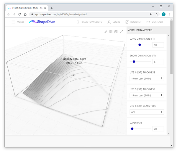
The pilot online represents a sample set of data, intended to provide a proof of concept and a methodology for designers to create their own.
As a matter of fact, since the tool is based on the ASTM standard and under its copyrights, it still requires designers beyond my group to acquire the document and to comply with its current revision.
While sharing the tool in its integrality is not permitted, sharing examples and insights is, and any questions welcome.
This tool is not intended to replace commercial software packages for a matter of accuracy: It is based on the E1300 charts whereas the software packages are based on the actual source data for the standard charts. We spot checked the tool for its compliance with commercial packages. The accuracy derives from the same graphical interpretation that a user would get from using the ‘paper’ charts, which we confirmed to be within +/- 2% of the software results.
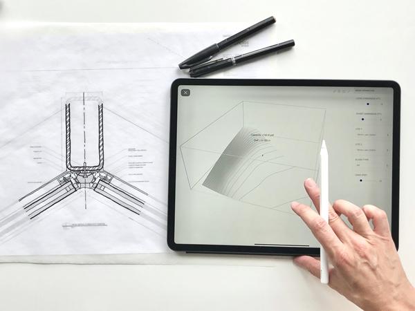
The tool is available online, and compatible with any computer, tablet, or smart phone, which allows the team to design glass on the go.
Sophie Pennetier,
Enclos Advanced Technology Studio
 600450


Add new comment