.")
This paper was first presented at GPD 2023.
Link to the full GPD 2023 conference book: https://www.gpd.fi/GPD2023_proceedings_book/

Authors: Christian Scherer, Chris Davis - H.B Fuller | Kömmerling Chemische Fabrik GmbH
1. Introduction
The principle of developing greener buildings must embrace the carbon consequence of the products assembled to form a glazed façade. For accuracy it must also evaluate any beneficial offsets delivered by those products and systems through the operational phase of the building. As our awareness of issues climate change increases, the pressure grows to perfect a circular construction economy that delivers a positive impact on the way we live and build. With an irreversible decline in the availability of raw materials there is an ever-greater requirement to make the most effective use of facade components in the first instance. The global building sector must focus on how we better achieve much "greener buildings" developed under the guiding principles of sustainability so greener in construction, greener in operation and greener in regeneration.
The use of intelligent sealants and adhesives is now a fundamental part of design and understanding their contribution to delivering high performance with longevity has never been more important in underpinning sustainable assembly design. High performance reactive thermoplastic based warm edge sealant systems such as Ködispace 4SG from H.B Fuller | Kömmerling combined with compatible high-performance secondary sealants will play an ever-increasing part in meeting the insulation challenge placed on glazed facades. Globally 40 percent of primary energy is consumed by, and 33 percent of all CO2 emissions is emitted by, buildings[1]. This paper seeks to set the landscape around these challenges and to understand the outstanding questions around the potential carbon consequences and benefits of using insulating glass units (IGU) in facades. This must be combined with the need to understand the contribution of uncompromising mechanical stability and the importance of embracing flexible and creative glass design.
2. Landscaping the embodied and operational carbon of insulated glass in facades
Accurately qualifying the corresponding values of the embodied and operational carbon associated with building components during the design phase is key to validating long term carbon signature of the building. Existing programmes already work to drive these initiatives i.e. BREEAM (UK), LEED (US), DGNB (DE), HQE (FR). The evaluation of embodied carbon will be derived from understanding the cumulative values of the materials used in the manufacture of the glazed assemblies. Inclusion of values for global transiting, the energy consumption used in the procurement, processing and manufacture of materials should provide an accurate if not transitory understanding of the embodied carbon consequence of the final façade design. Declarations are likely to be mandatory under the Environmental Product Declaration scheme (EPD), and a requirement under the Construction Products Regulation (CPR) 305/2011 will enhance a more detailed and regulated approach to modelling the embodied and carbon legacy of individual building design. For insulating glass assemblies this would be reflected in separately expressed carbon values for the glass, sealant and spacer system jointly contributing to a combined unit value.
However a fuller understanding of new principles such as the “building performance gap“, “the time value of carbon“ and “the carbon payback period“ [2] ask us to question the gap between the estimated and y “real time“ values i.e. the gap between tested values and the data reflecting experience in the field (Figure 1). Can we assemble better real time data to make building energy modelling more accurate in the future which is of particular importance as we experience ever greater extremes of climatic behaviour.
![Figure 1: Demonstrating the carbon payback period principle (Courtesy Will Wild, Arup [2].](/sites/default/files/inline-images/Fig1_337.jpg)
For glass facades it is clear that durable, high performance insulating glass comes with a higher embodied carbon consequence than lower specification assemblies, so adding more glass panes, laminated glass and coatings, naturally increases embodied carbon particularly where there is not the employment of significant sustainable energy sourcing and raw material strategies (Figure 2).
![Figure 2: Embodied carbon versus operational carbon consequence for glazing with improved insulation performances. (courtesy Will Wild, Arup) [2]](/sites/default/files/inline-images/Fig2_345.jpg)
In order to justify the use of glass it is essential to accurately demonstrate that the increased embodied carbon value can be offset over time by delivering reduced operational carbon values for the building. High-performance insulating glass manufactured using Ködispace 4SG reactive warm edge spacer technology can play a pivotal role in a sustained reduction of energy use during the building life cycle. Extended “effective“ service life is key to offsetting any increased embodied carbon consequence from the glass and coating parts. This is a function of maintaining a gas tight protective cavity over an extended timescale irrelevant of mechanical and climatic conditions.
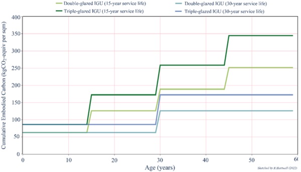
Therefore, ensuring long term insulation performance increases the time period before replacement is required and demonstrating that insulating glass improves the whole-life carbon performance of glazed facades. As the cavity becomes compromised by moisture the insulation performance worsens. The question raised is at what point should the insulation performance be considered ineffective. Previous research [2] has demonstrated that doubling the “effective” service of insulating glass can effectively halve the embodied carbon consequence from the original manufacture and installation assuming there is 0% post-consumer recycled material content included (Figure 3).
This encourages a debate around the methods and perceptions that surround the current evaluation of effective service life and how this changes as insulation values change within an IGU, in essence how we can close the “building performance gap” [1] .What we evaluate through standard test procedures may well not accurately represent what occurs currently in the field. It is noted by Madison Linkins-White, Robert Tenent and Zhiqiang Zhai in their investigation into the degradation of insulating glass in the U.S that “Because of the variety of testing methods and lack of field validation, there is little agreement on the most appropriate durability test. This further underscores the shortcomings of accelerated aging testing as it relates to actual IGU performance and durability”. [7].
3. Improving performance through extended IGU service life
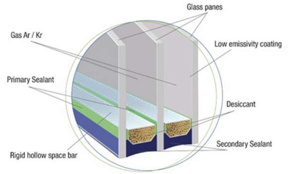
The prime contribution to thermal insulation performance in insulating glass is from low emissivity, metallised coatings treatments on the glass surfaces where optimum performance relies on functioning in a hermetically sealed dry air or gas filled environment (Figure 4).
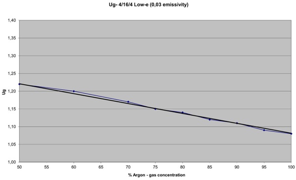
As moisture permeates into the cavity during service the desiccant materials, normally designed to absorb the residual moisture following assembly of the IGU, will become saturated and eventually fail thus removing capacity to absorb further moisture. The loss of gas content naturally impacts the Ug values and the negative impact of this erosion on performance can be seen in part in figure 5.
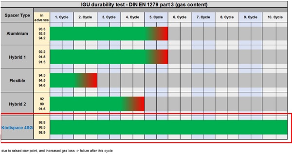
There are also additional questions around the full effect on insulation performance once the cavity is partly or fully compromised e.g. the impact of moisture on the long-term effectiveness of some metallised type coatings requires further clarification [7]. Therefore understanding that the enhanced adhesion properties associated with Ködispace 4SG reactive warm edge TPS based technology can help maintain dry air / gas tight environments for extended periods. This behaviour is central to de-risking accelerated degradation in the performance of IGU’s used in facade design. In addition, as an automatically applied TPS system with a captive desiccant matrix, it benefits from consistent four edge desiccant application. This technology is also proven to retain high volumes of argon gas during the initial filling process and this, combined with extremely low gas loss and moisture vapour ingress, demonstrate significant resilience over extended test cycles as demonstrated in figure 6.
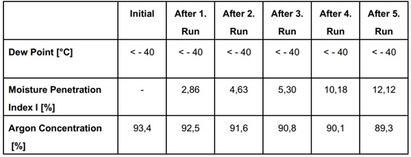
Tested to the protocols detailed in EN 1279:Glass in Buildings – Insulting Glass: Part 2 [5] reactive TPS technology demonstrates a measured gas loss of 4.1 % after 5 consecutive cycles with a moisture penetration value of 12.12% ( figure 7).
Guidance on gas loss rates parameters and absolute failure benchmarking detailed in En 1279 Glass in Buildings – Insulating Units: 2011 Parts 1 to 5 [5] offer some understanding of current expected service life expectations. With ongoing changes in climates and the pressure on reducing carbon generation the question posed asks if existing benchmarks can still be considered acceptable and should we look to extend the parameters of performance expectation. Therefore, a detailed understanding of how to significantly reduce gas loss in real time is important to understand the positive contribution an IGU makes to the ongoing operational carbon value of the building.
Extending service life with reactive TPS spacer systems
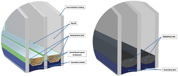
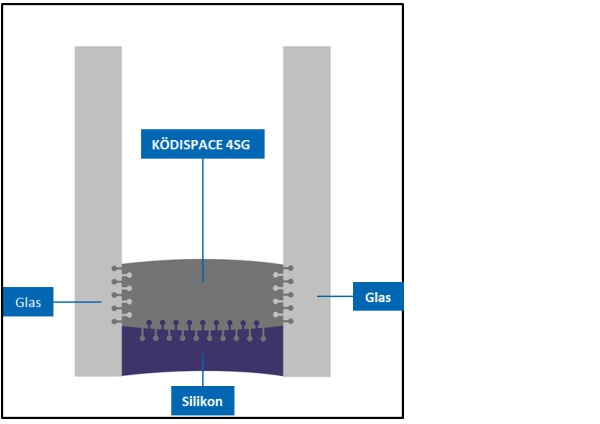
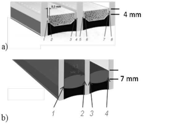
Basing a thermoplastic spacer system on polyisobutylene ensures the legacy of this material as a supreme primary sealant continues. In the case of Ködispace 4SG (figure 9) it becomes the basis of an integrated system that incorporates a desiccant matrix for dehumidifying the inter-module space [6]. This replaces separate spacer bar and desiccant assemblies as shown (figure 8) and is designed for use with high performance secondary sealants.
By utilising chemical adhesion to the surface of the glass it ensures that dislocation through adhesive failure is almost impossible. The key mechanisms for the chemical bonding are humidity and temperature driven hydrolysiscondensation reactions of the modified polymer and chemically active hydroxy groups on the substrate surfaces.(Figure 10)
Reducing the number of adhesive interfaces between the glass surface, spacer bar and secondary sealant also helps to reduce the potential risk of adhesive failure thus reducing the number of boundary layers and permeation pathways (Figure 11).
This robust bond is supported by flexible “elastic” based behaviour within the body of the polyisobutylene that helps to maintain mechanical integrity in both shear and pressure-based strain conditions and over a wide service temperature range. The bulk mass of the isobutylene based TPS system ensures that the bond to the glass surfaces remains stable despite the mechanical strains placed through the edge seal system under both long and short term loads. The opportunity for cohesive failure within the material or adhesive failure at the bond line is almost completely eliminated. Material laws derived from dynamic mechanical thermal analysis (DMTA) test data determine load characteristics for shear, torsion and pressure based on a visco-elastic model, which is calibrated to quasistatic mechanical performance. The analytical approach is translated to a numerical model for finite element mechanical modelling. The impact of mechanical loads modelled around the primary seal can be clearly demonstrated and compared to behaviour in conventional hollow bar and primary seal arrangements. Strain both at the bond line and in the body of the material are clearly shown in blue. With figure 13, reactive TPS, demonstrating significantly lower strains than that in figure 12, a standard hollow bar and primary seal arrangement. It is notable that, for visibility that the modelling of the strain dissipation in Ködispace 4SG (Figure 13) the finite element analysis (FEA) graphic is amplified by a factor of 9.
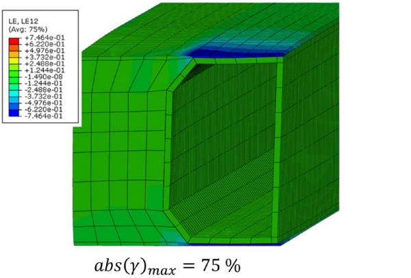
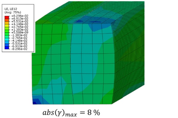
As the deformations experienced are many times smaller than those evident in the butyl edge component applied to a rigid spacer, this offers significant advantages in terms ensuring the tightness of the cavity. In addition, in the case of an elastic composite, the loads are removed via the secondary seal without local stress peaks, which is also assumed in conventional mathematical detection methods (see for example, [2], [5], [6]. Ensuring that the impact of any strain is mitigated at the primary seal bond face prevents breaching the gas tight seal even under the most onerous of mechanical conditions. Thus ensuring that more complex geometric designs i.e. 2 or 3 axial cold bends are not only possible but can be achieved without compromising the effective service life expectation of the IGU.
4. Creative design and mechanical stability with reactive TPS technology
Sustainable design also needs to allow architectural freedom and encourage creative design. The ease with which coaxial bent designs can be safely achieved with reactive TPS is no better demonstrated than in the glazed roof project at the Chadstone Shopping Mall, Melbourne, Australia (Fig 14). Here, the cold bending of each panel to form coaxial bent units installed into the extensive 2,100m2 roof structure, required a considered application of Ködispace 4SG material finite element analysis. Each IGU is required to accommodate onerous climatic conditions and simultaneous mechanical loads whilst maintaining gas tightness and consequently preserving the insulation and isolation performance within the cavity.

To ensure the entire glazed envelope is without weakness surety of performance must be guaranteed across all the IGU’s installed. This is achieved by utilising the fully automated application of the TPS edge spacer and silicone secondary edge sealant. This ensures that the accuracy of spacer placement is maintained with every assembly and maximises optical perfection. With a matt black look and without unsightly offsets, Ködispace 4SG forms an almost invisible spacer application. Dramatic events over the past years in Australia have heightened the need for the architectural community to give prime consideration to the carbon consequence of the designs constructed in their own “back yard”. However Ködispace 4SG not only enables safe creative design as at Chadstone mall but can also contribute significantly to balancing whole life carbon where IGU’s are used as safe carriers for advanced solar and energy harvesting technologies demonstrated in wider sustainable building design strategies.
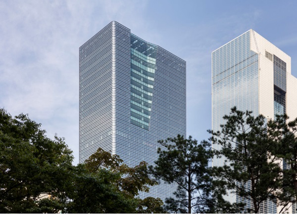
5. Utilising TPS insulating glass units in a holistic sustainable building design approach
By using an holistic approach the benefits of insulating glass with extended an service life can deliver enhanced environmental benefits when deployed with other sustainable glazing technologies. Understanding and balancing the operational and embodied carbon consequence of the building through its construction phase and operational life cycle was central to the design process for the 183m tall Parnas Tower in Seoul (figure 15). As a recipient of a gold LEED sustainability accreditation from the U.S Green Building Council, Parnas Tower harnesses the benefits of passive and dynamic glazing technologies. At the heart of this design is the understanding that, in order to maximise these progressive performances, the insulating glass assembly must demonstrate long term gas tightness and therefore moisture resistance.
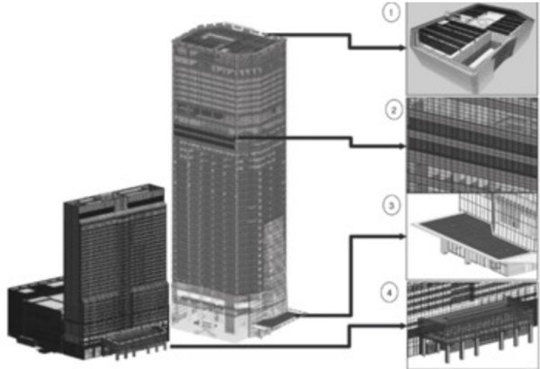
This holistic approach reduces the carbon impact of heating and cooling by employing near-surface geothermal heat pumps energising the building during the day but also storing precious energy to provide electricity at peak times. It also utilising ice storage to dissipate heat during the hot summer months provides highly efficient low carbon cooling. The progressive use of photo voltaic technologies is separated into building integrated photovoltaics (BIPV) incorporated within certain areas of the glazed façade alongside directly employed photovoltaic (PV) installations. The BIPV strategy sees some use of energy generation encapsulated within the insulating glass units. High performance IGU’s manufactured with Ködispace 4SG is not only restricted to safely encapsulating energy generation but also hosting electrochromic technologies used to create dynamic solar shading where moisture can dramatically affect the function of the sensitive cell technologies. Clever design also creates areas of direct PV cells on the roof top areas and into canopy systems. These wide-ranging strategies not only ensure flexibility across a wide range of climatic conditions but provide localised solutions that constantly work to reduce the building energy demands from increasingly stretched national power networks (Figure 16).
6. Summary
Developing sustainable architecture relies on the development of sustainable assemblies. Clearly glazed assemblies must perform at the highest level for the longest possible time to avoid or delay replacement. With double and triple glazed insulating glass units becoming standard specifications in most markets the environmental need to ensure effective longevity becomes ever more pressing. As climatic conditions and raw material supplies become more challenging our approaches and solutions must become more innovative. For insulating glass closing the performance gap will happen more quickly as we develop a clear and accurate understanding of performance and service life in the varying fields of operation. The need to reassess the acceptable benchmark of failure will be reliant on an honest understanding of IGU behaviour in service. Insulating glass units made with Ködispace 4SG reactive thermoplastic technologies with their improved thermal insulation and longer service life are clearly a key part of the solution.
References
[1] Sustainable glass architecture through intelligent adhesive and sealant solutions –Dr Christian Scherer, Chris Davis, Danny Suh - Advanced Building Skins 2022
[2] Balancing embodied and operational carbon in building envelope design - Will Wild, Arup.
[3] End-of-life Challenges in Façade Design: A disassembly framework for assessing the environmental reclamation potential of façade systems – Rebecca Hartwell, PhD Candidate, University of Cambridge / Prof Mauro Overend, T.U Delft
[4] Dedication to 4SG material law authors Scherer, C.; Scherer, T.; Semar, E.; Wittwer, W. (2019) Ködispace 4SG, der Schlüssel für energieeffiziente kaltgebogene Structural-Glazing-Fassaden in: B. Weller and S. Tasche [Hrsg.] Glasbau 2019, Berlin: Ernst und Sohn, S. 439–449.
[5] EN1279: 2018 Glass in Buildings – Insulating glass units [6] Reactive thermoplastic spacer for energy-efficient cold-bent structural glazing facades – Dr Christian Scherer, Dr Thomas Scherer, E. Semar, Dr Wolfgang Wittwer – Advanced Building Skins 2019
[7] Degradation of Insulating Glass Units: Thermal Performance Measurements and Energy Impacts – Madison Likins-White, Robert C. Tenent and Zhiqiang Zhai - MDPI