First presented at GPD 2019
Here, an innovative concept is proposed, based on the use of cold-twisted square elements and on the exploitation of their buckling phenomenon, causing the shape modification from double-curvature anticlastic to singlecurvature shape, where bending essentially occurs along one diagonal. This is applied to the design of a transformable greenhouse for protected agriculture, suitable for strong modification of openings and ventilation, allowing to fully exploit the high-deformability of thin glass.
The greenhouse roof is composed by four curved thin glass elements, with a metallic frame designed to provide a preferential direction for the bending deformation, having the semblance of “petals”. The cell’s curvature can be modified by changing the support’s position. This allows to modify not only the shape and the inclination of the surfaces forming the roof, thus changing lighting and irradiation, but also size and shape of the openings, strongly affecting the air flow. Numerical analyses and “designby-prototyping” strategy, entailing the construction of a reduced-scale mock-up of the greenhouse, have demonstrated the feasibility of this concept, highlighting the huge range of obtainable configurations and opening systems.
Introduction
In the last decade, architecture has developed new ways to respond to issues related to energy building performance and people’s comfort, changing to transformable and dynamic objects. In particular, kinetic and adaptive façades proved to be an effective approach to provide natural lighting and fresh air and to increase the building energy efficiency [1], [2].
Thanks to its transparency and capacity of diffusing the light while delimiting a place, the use of curved structural glass is constantly growing and represents the leading feature of modern architectural trends. In very recent years, several authors [3], [4] are proposing and exploiting the pioneering use of thin glass, with thickness lower than 2 mm and originally conceived for electronic screens, in the built environment.
Indeed, due to its low weight, high impact and scratching resistance, excellent optical quality and ability to be bent up to small radii, it is proving to be the optimal material for the construction of extremely deformable structural elements for façades and building skins.
This opens doors for architects and designers to its pioneering use as a flexible and light weight cladding material. Recently, several authors have proposed the use of thin glass for the construction of kinetic and adaptive elements and façades [5], [6] where this material allows to obtain the large deformations and movements required to maintain a dynamic optimum in performances with regard to energy, climate and comfortrelated aspects.
In [7], an innovative concept for the structural use of cold-bent thin glass is proposed. The use of elements with hyperbolic paraboloid shape, a common geometry for cold-bent glass that may be obtained by twisting the plate through the action of opposite concentrated out-of-plane forces at the plate corners. Their buckling phenomenon [8], changing the shape from anticlastic to a symmetric cylindrical surface where bending is essentially unidirectional along one of the diagonals, was exploited to obtain shape modification with high level of distortion.
Here, this study is extended by accounting for the possibility of non-symmetric deformation of the considered element, to obtain a wider range of shapes. This allows not only to increase the obtainable combinations of shapes and movement of a façade (or roof) composed by a modular assembly of the considered elements, but also to confer aesthetic dynamism to the envelope.
The feasibility of this proposal is tested by considering a structure with relatively small scale, i.e., a transformable and movable glass greenhouse for protected agriculture, a structure by its nature suitable for strong modification of openings and ventilation. However, this study could be the basis for the application of this concept in larger structures, as building façades and roofs. The greenhouse roof is composed by four curved elementary cells, having the aesthetic appearance of “petals”.
The structural design has been strictly correlated with the production of a reduced-scale model, showcasing the kinetics of the roof and its obtainable transformations. The “design-by-prototyping” strategy has provided a real-time feedback on the possible issues related to the construction of the transformable elements and their kinetic. It has consistently helped the study of the geometric and kinetic properties not only of the single element but of the whole greenhouse, its possible geometric transformations and the various obtainable shapes.
The concept design
Consider the initially-flat square panel shown in Figure 1a, fixed at two opposite corners B and D. By prescribing the same value of out-of-plane displacement to corners A and C, it tends to deform into an anticlastic hyperbolic paraboloid shape. At a certain level of distortion, it buckles into a single-curvature configuration where one of the diagonals tends to straighten [8].
But, due to it slenderness, a thin glass element tends to deform into a developable surface [6], without stretching or compressing of the mid-surface of the glass, allowing to maintain a low stress-level. This means that, whenever subjected to coldtwisting, a thin glass panel bent into a singlecurvature shape for level of distortion much lower than the ones that can be appreciated with the naked eye [7].
This property can be exploited to design coldbent single-curvature elements with high distortion levels. The reference configuration for the curved element is, hence, that shown in Figure 1b, where bending occurs along A’C’ diagonal. Obviously, there are two equivalent configurations, because the unidirectional bending may equivalently occur along one diagonal or the other. Hence, to avoid uncontrolled and abrupt change of curvature, it is of paramount importance to design a metallic frame so to provide to the element a preferential direction for the bending deformation, for example by means of a metallic rib along diagonal BD.
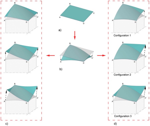
The element is supported by a substructure, designed so as to fit with the curved edges in this reference configuration. Starting from the reference configuration (Figure 1b), different shape modifications can be obtained by keeping fixed corners B and D, while moving A’ and C’ in the out-of-plane direction, leaving the in-plane translational degrees of freedom.
A first family of transformed shapes, shown in Figure 1c, may be obtained by prescribing the same value of out-of-plane displacement to points A’ and C’. In such away, both in reference and deformed configurations the bending occurs along the AC diagonal, that changes its concavity. As shown in Figure 1c, this solution allows to deform the roof in several intermediate positions. This possibility, leading to configurations symmetric with respect to the BD diagonal, has been widely studied in [7].
Here, we will focus on unsymmetric configurations of Figure 1d:
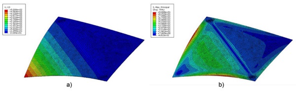
- Configuration 1 may be obtained, starting from the reference curved configuration, by keeping fixed three points (for example, A’, B and D), while moving the forth (C’) in the upward direction, up to its original position. Notice that two edges (A’D and A’B) are in contact with the underlying structure.
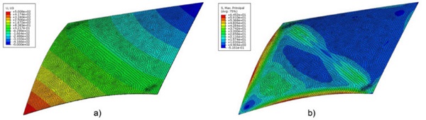
- By further increasing the upward displacement of the point C’, Configuration 2 may be obtained. In this configuration, the diagonal BD is not straight.
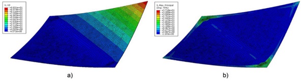
- Configuration 3 corresponds to the case of a moving point (A in Figure 1d) positioned in the initial configuration (i.e., in the position of Figure 1a), with the other (C) with prescribed upward displacement. In this case, the plate deforms into a developable surface, with single curvature in the direction of diagonal AC.
Obviously, other solutions may be obtained by moving points A’ and C’ in intermediate positions.
Structural Design
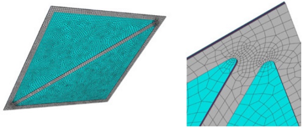
The hybrid cell is composed by a square glass panel 2 m x 2 m of thickness 2 mm, contoured by a high-performance ferritic stainlesssteel frame with one diagonal rib, to confer to the hybrid cell a preferential direction to the bending deformation, with width 80 mm and thickness 2 mm. The frame is positioned on the inner face of the cell, and direct contact with glass is avoided by interposing EPDM, bonded by means of structural acrylic adhesives.
Numerical analyses have been performed, with Abaqus code, to design the hybrid cell to withstand the loads necessary to cold bending and to shape transformations, with maximum out-of-plane displacement of 500 mm, as well as the self-weight and the snow load, in accordance with EuroCode 1.
Figure 2 shows the solid model, as well as the discretization used in the FE analyses. Glass and steel components have been modeled with linear elastic material behavior, while third order Ogden model has been used for EPDM [9], having strength higher than 10 MPa [10]. According to [4], the strength of thin glass has been assumed equal to 200 MPa.
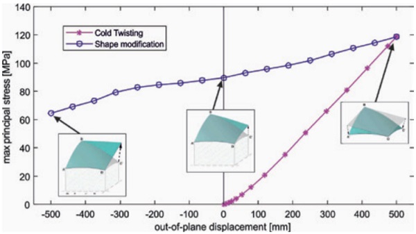
In the first step of the numerical experiments, the cold-twisting is performed by prescribing a downward displacement of 500 mm to two opposite corners (A and C), while leaving their in-plane translational and the rotational degrees of freedom. The maximum tensile stress in the thin glass panel is about 120 MPa, lower than its characteristic strength. The Von Mises stress in the steel frame exceeds the material strength (300 MPa) only in very localized regions of the frame, in proximity of the junction between external frame and diagonal rib. The maximum tensile and shear stress in the EPDM layer are lower than the design values.
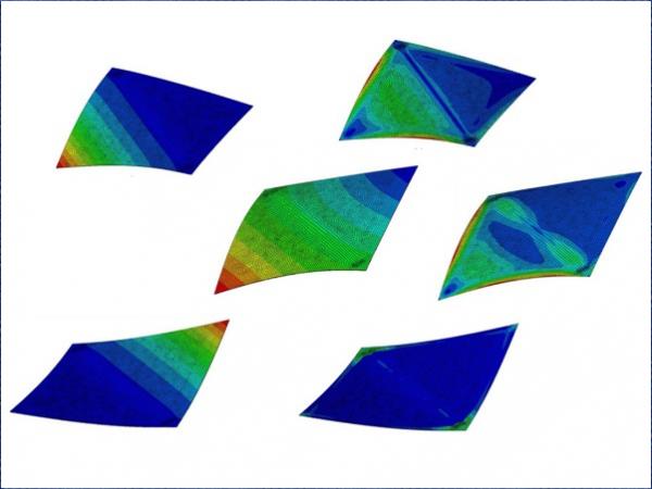
In a second analysis step, additional out-ofplane displacement is prescribed to corner points A’ and/or C’. Since in [7] similar analyses have been performed on an analogue hybrid cell, with different adhesive, with regard to symmetrical deformation modes (see Figure 1c), here only results related to unsymmetric modes (Figure 1d) are recorded. Figures 3, 4 and 5 shows the results of the FEM analyses, in terms of both out-of-plane displacement and maximum principal stress in the glass panel, for configurations 1, 2 and 3, respectively.
For all the configurations, the maximum principal stress in glass is lower than in the reference configuration. Graph in Figure 6 show the numerically obtained relationship between prescribed out-of-plane displacement of point C’ and maximum principal stress in glass, for both cold twisting phase and shape modification from the curved reference configuration phases.
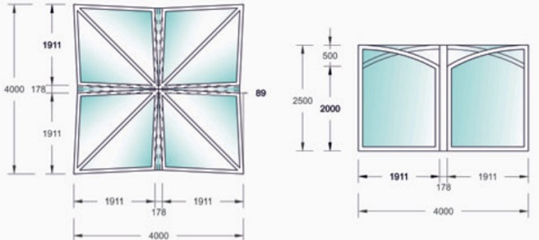
Drawings in Figure 7 show the greenhouse’s roof and substructure, in the reference “closed” configuration. The structure has approximatively square shape, with slightly concave edges, with overall size of 4 m x 4 m and maximum height of 2.5 m. The substructure consists into perimetric walls, and four curved ribs connecting the center of each edge with a central square column.
The reduced-scale model
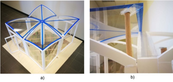
The reduced scale mock-up of the whole greenhouse shown in Figure 8a, of approximatively 0.6×0.6 m (scale factor 1:6.67), has been constructed to study the kinetics of the roof and its obtainable transformations. The square cells, with edge length of 300 mm and constructed with square acetate foils 400 µm thick, have been curved in the reference configuration by prescribing a vertical displacement of the cell corners of 75 mm with respect to the undeformed (flat) configuration.
The metallic elements are represented by blue stripes, while the substructure has been realized with foam core cardboard, and panel composing the walls of the greenhouse have been made with 100 µm thick acetate foils. The shape modification of the roof is obtained by vertically moving the corners’ points of each cell, by means of wooden vertical rods that can be moved upward and downward inside hollow columns located in proximity of the midpoint of the greenhouse edges. A dovetail-shaped joint (Figure 8b) is used to connect the plate with the vertical rod, to leave the in-plane translational and rotational degrees of freedom.
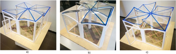
The design-by-prototyping strategy has confirmed, at least from a qualitative point of view, that the considered deformation modes do not entail uncontrolled changes of curvature and snapping phenomena. Furthermore, it has consistently helped the study of the kinetics, highlighting in particular the importance of the study of the vertical actuator for the cell vertex. Figure 9 shows several possible configurations for the roof, obtained by using deformation modes 1, 2 and 3 shown in Figure 1d and highlighting the huge range of obtainable shapes and opening systems. Since these modifications strongly affect the flow of air, they have a noteworthy impact on the ventilation of the greenhouse.
Conclusions
This paper presents an innovative application of thin glass in the built environment, fully exploiting its flexibility to construct highly deformable transformable structural elements. The considered basic element is a hybrid elementary cell composed by a square thin glass panel contoured by a ferritic stainlesssteel frame with a diagonal rib, cold-bent, along a diagonal, into a developable cylindrical surface.
Starting from this configuration, the shape of the panel can be modified by keeping fixed the two corners’ points belonging to the straight diagonal, while moving the other corners in the out-of-plane direction. Both symmetric (with respect to the straight diagonal) and unsymmetric shapes can been obtained. The composite cell has been numerically designed to withstand the loads necessary to the cold bending and to the shape modification, as well as the self-weight and the snow load.
The “proof of concept”, i.e., the use of the hybrid cells for the construction of a transformable greenhouse for protected agriculture, has confirmed, even if from a qualitative point of view, the feasibility of the proposed solution.
References
[1] C. Linn, 2014. Kinetic Architecture: Design for Active Envelopes, Images Publishing.
[2] A.H. GhaffarianHoseini, et al., 2013. Sustainable energy performances of green buildings: A review of current theories, implementations and challenges. Renew Sust Energy Rev 25, pp. 1-17.
[3] R.R. Silveira, 2016. Flexible transparency: A study on thin glass adaptive façade panels, MSc Thesis, Delft University of Technology, Delft (NL).
[4] P. Ganatra, 2016. Bamboo and thin glass: Structural analysis of bending bamboo and thin glass, MSc Thesis, Delft University of Technology, Delft (NL).
[5] R.R. Silveira, C. Louter, C and T. Klein, 2018. Flexible Transparency-A Study on Adaptive Thin Glass Façade Panels. Proceedings of Challenging Glass 6, pp. 135-148.
[6] J. Neugebauer, et al., 2018. Movable thin glass elements in façades. Proceedings of Challenging Glass 6, pp-195-202
[7] L. Galuppi, 2018. Transformable Curved Thin Glass Greenhouse. Int J Struct Glass Av Mat Res 2, pp. 198-217.
[8] L. Galuppi, S. Massimiani and G. Royer-Carfagni, 2014. Buckling phenomena in double curved coldbent glass. Int J Non-Linear Mech, 64, pp.70-84.
[9] Ch. Feichter, Z. Major, and R. W. Lang, 2006. Deformation analysis of notched rubber specimens. Strain 42.4, pp.299-304.
[10] http://www.designerdata.nl/plastics/elastomers/EPDM