Authors: Chiara Bedon and Salvatore Noè
Source: Vibration 2021, 4(4), 836-852; MDPI
DOI: https://doi.org/10.3390/vibration4040047
Abstract
The vibration performance of pedestrian structures has attracted the attention of several studies, especially with respect to unfavourable operational conditions or possible damage scenarios. Specific vibration comfort levels must be commonly satisfied in addition to basic safety requirements, depending on the class of use, the structural typology and the materials involved. Careful consideration could be thus needed at the design stage (in terms of serviceability and ultimate limit state requirements), but also during the service life of a given pedestrian system. As for structural health monitoring purposes, early damage detection and maintenance interventions on constructed facilities, vibration frequency estimates are also known to represent a preliminary but rather important diagnostic parameter. In this paper, the attention is focused on the post-breakage vibration analysis of in-service triple laminated glass (LG) modular units that are part of a case-study indoor walkway in Italy. On-site non-destructive experimental methods and dynamic identification techniques are used for the vibration performance assessment of a partially cracked LG panel (LGF), compared to an uncracked modular unit (LGU). Equivalent material properties are derived to account for the fractured glass layer, and compared with literature data for post-breakage calculations. The derivation of experimental dynamic parameters for the post-breakage mechanical characterization of the structural system is supported by finite element (FE) numerical models and parametric frequency analyses.
1. Introduction
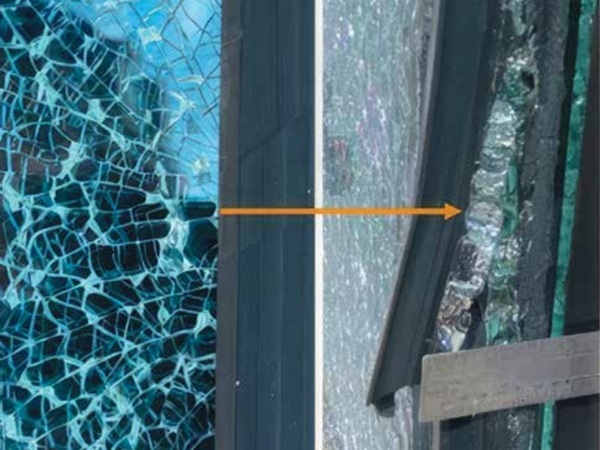
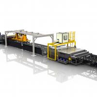
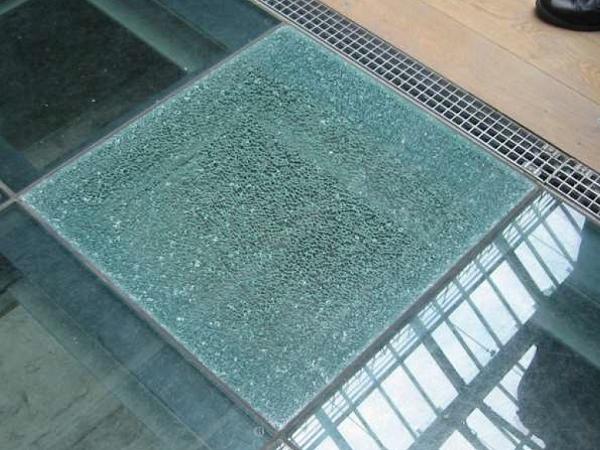
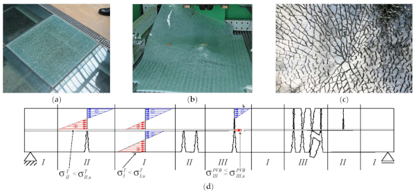
The optimal design and structural performance assessment of laminated glass (LG) elements for building applications is a challenging task for designers and has an impact on the safety of customers. For such applications, the post-breakage residual stiffness and strength of LG components is of utmost importance (Figure 1a–c), especially in the presence of extreme design actions [1]. From a practical point of view, the post-breakage performance of LG elements is characterized by the presence of glass fragments that are expected to adhere to the inter layers. This effect gives a certain residual structural capacity to the composite system, as far as the glass fragments are locked in place. Several aspects are, however, implicitly involved in the definition of key mechanical parameters that govern the complex post-breakage response of LG members (Figure 1d), like the fragmentation of glass, the fragment size, the interlayer type, etc. [2]. In this regard, several research studies can be found in the literature to address and support the definition of experimental feedback and/or mathematical models that could be used to support the post-breakage safe analysis and performance of LG members variably loaded and restrained in a building context. These studies include pre-cracked simple panels [3,4], balustrades [5], columns [6], beams and connections [7,8,9], and others [10,11,12].
In the present paper, attention is focused on the experimental and Finite Element (FE) numerical analysis of in-service LG modular units acting as pedestrian elements that are affected by partial glass fracture and ordinary walking conditions. In the framework of structural health monitoring approaches for constructed facilities, it is in fact known that frequency control can provide useful feedback about possible damage and residual capacities of the structure [13,14]. Accordingly, the on-site experimental measure and comparative analysis of vibration parameters for various structural systems and constructional materials are typically associated to efficient early maintenance interventions [15]. Several studies can be found with a focus on variation of vibration frequencies [16,17], modal damping [18,19] or modal shape and curvature [20,21]. In this regard, LG members can be intended as load-bearing components in the same way as traditional constructional systems, and thus susceptible to conventional structural health monitoring procedures.
Otherwise, detailing intrinsic mechanical properties and components for LG systems should be properly taken into account. As shown in this paper, the mechanical and vibrational performances are expected to strongly modify especially in presence of possible glass fracture, i.e., from the uncracked to the post-breakage stages, and potential risks may occur for customers. To this aim, post-breakage design assumptions are commonly aimed at verifying the residual stiffness and strength of LG members affected by possible glass fracture. On the other hand, the available simplified design calculation approaches may not capture the actual mechanical features and structural response of fractured LG members. Even major attention in design and analysis is then required for pedestrian LG members, due to human–structure interaction phenomena [22] and their possible combination with unfavourable subjective reactions of walking occupants [23].
In this regard, an original on-site experimental investigation is presented for an in-service glass walkway characterized by a composite LG cross-section affected by partial fracture. The attention is focused on the fundamental frequency analysis and its sensitivity to glass breakage, as well as on the use of simple frequency estimates for the early detection and quantification of damage in LG structural systems. The experimental analysis is carried out for selected modular units with identical size and boundaries, under ordinary walking conditions, but characterized by intact or fractured glass layers respectively. The experimental outcomes are further addressed with the support of FE numerical models able to capture the dynamic response of the examined structural system. Based on classical inverse techniques, mechanical parameters are derived in the post-breakage stage and discussed in terms of the literature.
To this aim, Section 2 summarizes some background design concepts for collapse prevention of LG members, and looks at the multiple aspects that may affect the vibration performance of post-breakage pedestrian elements. As a preliminary step, Section 3 explores the vibration frequency of a simply supported triple LG module, so as to assess the effects of major influencing parameters. The attention is given to damage severity in the fractured glass layer, as well as the stiffness and mass contribution of glass fragments for the residual LG section, but also the strength of the mechanical bond for the LG components and the mass contribution of walking occupants.
Successively, Section 4 introduces a series of original on-site experimental measures for the case-study walkway under various walking conditions. With the support of FE numerical analyses, some considerations about frequency sensitivity to damage and the use of equivalent mechanical parameters for fractured glass in LG components are discussed in Section 5.
2. State of the Art
2.1. Reference Limit States for Design
The structural design of glass members and assemblies is typically characterized by demanding performance requirements for primary elements but also for connection and restraint detailing. According to existing design guidelines [24], the reference limit states (LS) for glass elements are service limit state (SLS), ultimate limit state (ULS) and collapse limit state (CLS). The SLS considers the uncracked structural element (“LGU”, in the following) subjected to the characteristic design loads and is notoriously expected to assess the deformability of the structural element. Maximum deformation limits are provided by guideline documents and standards, depending on a multitude of parameters (such as the cross-sectional layout and the boundary configuration), in order to ensure appropriate functionality. The ULS considers the structure subjected to extreme values of external actions, and are made up of: (i) ULS for glass breakage, (ii) ULS for breakage of materials used in combination with glass, or (iii) ULS for interface failure. The ULS calculation consists in verifying that the stress at each point, as a consequence of the most unfavourable load combination, is lower than the material design strength. Also for resistance verification, the reference design strength value should be separately calculated, case by case, including a set of coefficients and safety factors [24].
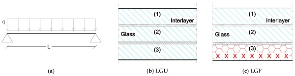
Finally, the CLS considers the glass element as fully or partially fragmented. The CLS is therefore aimed at guaranteeing that a construction with structural glass elements has adequate structural behaviour in the post-critical phase at both global and local levels. The need to consider the CLS derives from the intrinsic brittleness of the glass, and also from the possibility—still remote—of spontaneous breakage. The CLS must consider this possibility, verifying that the fractured element guarantees the load-bearing capacity for a suitable fraction of the loads at the ULS and/or the SLS. Operatively, the CLS considers two possible scenarios, namely (i) a structural system made of glass elements or (ii) a single structural glass element. The CLS must take into account the structural situation that emerges after one part of the load-bearing structure has cracked. As such, the CLS verifies that the damaged structure preserves a suitable residual load-bearing capacity. For LG slabs like in Figure 2, for example, the practical analysis assumes that one of the composing glass layers may crack (i.e., “LGF” section, in the following), and consequently has to be disregarded for residual stiffness and resistance contributions. In general terms, moreover, it is worth noting that:
- In more complex situations, the minimum performance requirements that the damaged structural must guarantee must be established ad hoc. The structure must, in any case, guarantee “fail safe” behaviour, with specific reference to hierarchy, system redundancy and resilience. The residual load-bearing capacity must include, as a minimum, the characteristic values of the self-weight of the structure;
- the single glass structural element must guarantee section redundancy, never intended as an increase in the sheet thickness, but as an increase in the number of glass layers. For laminated glass, the performance of a package made up of an interlayer and one or more fragmented glass sheets must be properly defined.
2.2. Vibration Frequency of Laminated Glass Elements
For the mechanical model of Figure 2a, the system in free vibrations satisfies the differential equation of motion for slender Euler–Bernoulli beams [25]. The fundamental frequency in the presence of ideal supports can be rationally calculated as:

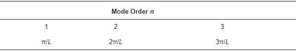
with n the mode order, h the monolithic thickness (or effective thickness hef, for LG cross-sections), E the modulus of elasticity (MoE) of glass, while β is the wave number in Table 1.
Table 1. Reference wavenumbers βn for simply supported slender beams.
For LG members, various literature studies emphasized that the actual stiffness of the composite system should be properly addressed in elastic conditions, because it strictly depends on the shear coupling effect of the bonding interlayers. For a given bonding film of typical use for structural glass applications, the real term of shear stiffness (storage modulus G2,0) and the imaginary part (loss modulus G2,ω) are both involved in the frequency domain:
![]()
Common materials in use for LG layers have a typical visco-elastic behaviour that can be affected by material properties, vibration frequency and operational conditions. This turns out in an effective thickness hef = hef(ω) that is subjected to iterative modifications with the dynamic stiffness of interlayers. Additional issues may arise from delamination of bonding layers [26,27]. Finally, special calculation methods should be taken into account to assess the vibration performance of LGF configurations as in Figure 2.
2.3. Design of Pedestrian Glass Sytems
It is worth mentioning that design requirements summarized in Section 2.1 represent fundamental steps of the overall procedure, in the same way as frequency sensitivity considerations in Section 2.2. Moreover, they still disregard those pedestrian systems composed of structural glass may be subjected to unfavourable vibrations due to occupants. The vibration response of glass structures is a relatively recent research topic [28,29,30,31].
As a general rule, glass slabs should be verified against vibrations under operational conditions in the same way as pedestrian structures composed of other constructional materials [32]. Possible critical aspects of glass pedestrian structures, in this regard, can be represented by typically small thickness-to-size ratios, high flexibility and slenderness, unconventional or limited number/size of restraints (i.e., point supports, etc.), see [33,34]. Additional uncertainties can then derive from the possible/progressive degradation of materials and restraints (as for viscoelastic interlayers [26,27]), hence resulting in even marked variations of the fundamental dynamic properties. In general terms, key parameters are represented by the motion features (i.e., pacing frequency and phase, walking speed, stride length, etc.), and dedicated tools are necessarily required for reliable analyses. Acceleration peaks and corresponding structural frequencies must satisfy a range of limit values for comfort prevention [34].
3. Preliminary Considerations
3.1. Research Goal
For the present research study, specific attention is focused on the vibration performance analysis of a partially fractured LG module, and thus on the combination of design recommendations and calculations assumptions in Section 2 such as basic vibration frequency issues. Attention is in fact given to the dynamic identification of damage due to the presence of fractured glass layer for LG pedestrian systems. The typical result is a cross-section in accordance with Figure 2c, where the mass of fractured layer is still in place, while the bending stiffness is expected to be highly affected by fracture propagation. In order to explore and quantify damage consequences in terms of vibration serviceability assessment, a case-study walkway is taken into account (Section 4), with a focus on frequency estimates under various walking conditions. For a more detailed analysis of experimental outcomes, however, preliminary assumptions and simple comparative data are presented in Section 3.2 and Section 3.3.
3.2. Literature Approaches for Post-Breakage Performance Assessment
Due to intrinsic material brittleness, the post-breakage performance analysis and assessment of fractured LG elements is a crucial research issue. The possible quantification of damage amount and its correlation with post-breakage resistance and stiffness is strictly related to robustness quantification, and hence reflects on the definition of design requirements and performance indicators that must be satisfied. In this regard, several research studies can be found in the literature for cracked LG members characterized by a multitude of boundary and loading conditions. Theoretical and FE numerical investigations can also be found for various practical applications.
Zhao et al. [3], for example, experimentally investigated the out-of-plane bending performance of pre-cracked double or triple LG plates in their post-breakage stage. The study was extended to a wide set of interlayer and glass type combinations, so as to derive useful outcomes for design. On the other hand, the experimental analysis was primarily focused on LG elements characterized by all glass layers damaged, and no intermediate configurations as for the CLS in Figure 1 were taken into account. In [5], Kozlowski investigated experimentally and numerically the dynamic performance of fully tempered (FT), double LG balustrades under a pendulum test setup.
The attention was focused on the mechanical characterization of pre-cracked LG sections, and thus one of the two constituent glass layers was preliminarily fractured. Under a twin-tyre impact for the fractured layer on the compressive or tensile side of the LG balustrade in bending, the experimental and numerical analysis resulted in the proposition and calibration of an isotropic, equivalent MoE for fractured glass (Efg, in the following) that could be used to simplify the post-cracked analysis of LG members, so as to replace the nominal glass MoE (E = 70 GPa). More specifically, the equivalent Efg parameter was quantified in 17.5 GPa (≈1/4th the uncracked value E) and 2.35 GPa (≈E/30th) for the fractured glass layer in compression or tension, respectively [5].
3.3. Post-Breakage Frequency Analysis of Laminated Glass (LG) Elements
The first step of the current investigation is dedicated to the frequency analysis of a simply supported LG panel as in Figure 3. As for pedestrian systems, glass fracture is assumed located in the bottom LG layer, which is expected to suffer for major tensile stresses under the sustained vertical loads. The composite panel is described with a triple LG section, has nominal dimensions of 1.35 m × 2.65 m and it is linearly supported along the short edges only. Under the assumption for the system of a beam-like fundamental vibration mode as in Equation (1), the corresponding frequency is supposed to modify from the unfractured towards the damaged/post-breakage configuration.
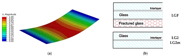
Preliminary parametric calculations are herein presented for a LG section composed of 3 mm × 12 mm glass layers, bonded by 0.76 mm thick interlayer foils (PVB®). Given the above assumptions, the LG system is characterized by total glass mass in the order of MLGU = 322 Kg (2500 kg/m3 the material density). The nominal material density is taken into account for intact and fractured glass layers. As for design calculations against short term live loads (room temperature), the PVB layers in use are assumed to offer a nominal MoE up to Eint = 24 MPa, which is relatively small compared to intact glass (E = 70 GPa) and typically associated to weak mechanical bonding of glass components. At this stage, frequency predictions are carried out disregarding the reciprocal variation of interlayer stiffness and the corresponding variation of LG frequency, as expected from Section 2. In doing so, the additional sustained mass of possible walking occupants (M) is also preliminarily disregarded. Regarding the fractured glass layer for the LGF setup in Figure 3b, finally, the equivalent MoE for the bottom layer in tension is progressively modified in the range from Efg = 70 GPa (uncracked glass, Efg ≡ E) and reduced down to Efg = 7 MPa (Efg ≡ E/10,000).
For comparative purposes, partial fracture in the LG section is also accounted for by means of two additional simplified numerical approaches (LG2 and LG2m in Figure 3b), that is fully disregarding the fractured bottom layer from the composite LG section. This means that the LG2 model removes both the stiffness and mass contributions for the bottom layer, and focuses on the bending analysis of a simple double LG section only (MLG2 = 215 Kg). The LG2m model, with identical geometrical properties, is inclusive of mass contribution only for the fractured layer (MLG2m = MLGU = 322 Kg).
Figure 4a shows the variation of fundamental vibration frequency (f1) for the triple LGF module as a function of damage severity in the fractured glass layer (i.e., Efg). The LGU frequency value in Figure 4a corresponds to the fully uncracked, triple LG panel (f1 = 13.08 Hz). The LG2 and LG2m frequency predictions are given under the assumption of a simplified double LG section only. The conventional frequency limit value of 8 Hz against vibration discomfort is also reported in the chart. The LGF red curve is obtained by changing progressively the Efg value for the bottom glass layer. Finally, Figure 4a emphasizes the equivalent MoE values that have been calibrated in [5] for fractured FT glass under tension or compression.
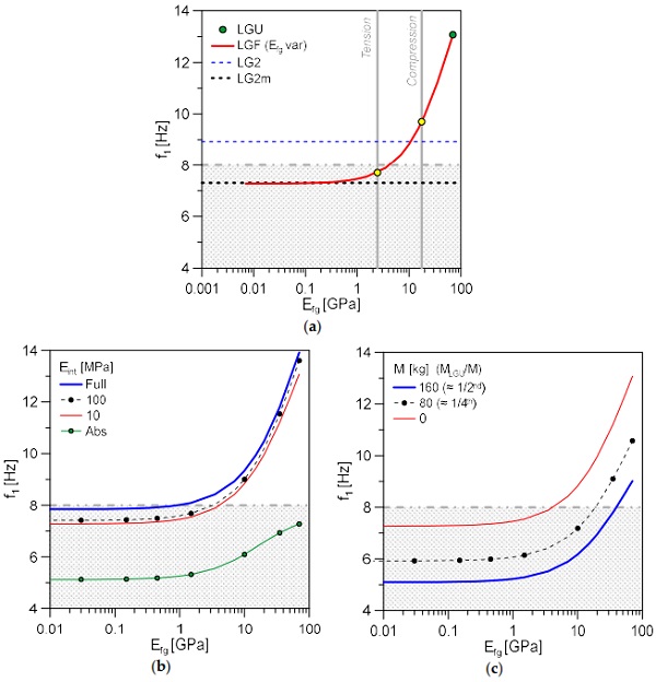
As far as the LGF estimates are compared with values from [5], it can be noted that Efg in tension is associated to mostly null bending stiffness contribution for the fractured layer (−41.1% the LGU value), while the Efg value in compression from [5] can offer a certain post-breakage stiffness contribution to the LG panel (−25.8% the LGU). For the present worked example, the LGF frequency decreases to −44.4% the LGU system.
Frequency values corresponding to LG2 and LG2m models are calculated in f1 = 8.93 Hz and f1 = 7.31 Hz, respectively. As far as Efg tends to zero for the LGF system, as expected, the fundamental frequency progressively tends to the LG2m frequency. Compared to LG2m (i.e., design approach), the mass contribution of cracked glass fragments manifests in an additional ≈ +12% frequency increase. The residual mass contribution of fractured glass layers is thus responsible of significant modifications of dynamic parameters. Worth noting in Figure 4a that—as far as the conventional frequency value of 8 Hz is taken into account as a reference for vibration serviceability purposes—the examined LG panel would be able to satisfy the minimum recommended fundamental frequency for human comfort under a limited number of damage configurations only.
In this regard, additional crucial aspects for the current calculation are represented by human–structure interaction indicators (i.e., analysis of unoccupied or occupied LG module). Among others, the interlayer stiffness as in Equation (2) turns out in a frequency modification as in Equation (1). Figure 4b, in this context, shows the effects of weak (“Abs”) or more rigid (“Full”) interlayer foils for the selected LG module (i.e., variable Eint modulus for the LGF model). Lack of bonding for glass panels typically results in severe reduction of vibration frequencies, both in uncracked or fractured configurations.
Regarding the analysis of pedestrian components, finally, the effect of sustained masses M from the walking occupants can involve additional severe modifications of vibration parameters. This can be seen preliminarily in Figure 4c, where comparative data are proposed (with Eint = 24 MPa) for the empty slab (M = 0), or for two occupied configurations (M = 80 Kg and M = 2 × 80 = 160 Kg respectively). In LGU conditions, it is possible to note that the sustained mass decreases to ≈−19% or ≈−30% the corresponding frequency f1. The frequency decrease in post-breakage conditions (Efg < 70 GPa) is mostly constant for the proposed calculations.
4. On-Site Experimental Investigation
4.1. Layout and Geometry
The experimental program was carried out in August 2021. The LG modular units object of investigation are part of the indoor pedestrian system serving the Basilica of Aquileia (Italy), and partially experimentally analysed in [32,33,34]. For the present study, the attention is focused on two original modular units (from a set of 39 elements) that are part of the Crypt of Excavations suspension path (Figure 5a).
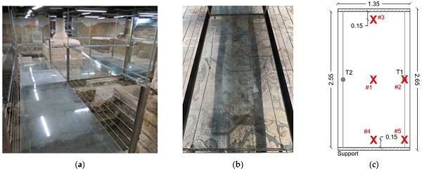
The reference LG panel has total dimension of 1.35 m × 2.65 m (Figure 5b,c). The slab consists of a triple section composed of FT glass layers (3 mm × 12 mm in thickness) and interposed PVB foils (0.76 mm their thickness). An additional protective layer made of annealed (AN) glass (6 mm in thickness) is positioned on the LG top surface (Figure 6). The mechanical interaction between LG and the top AN layer is ensured by contact only.
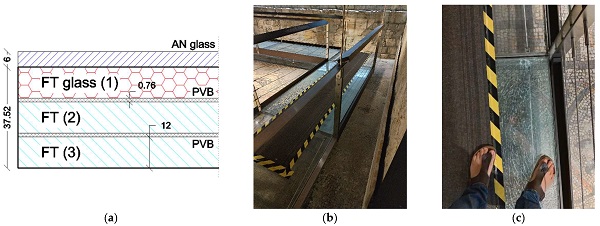
The tested modular units are linearly supported along the short edges (Figure 5c). To limit large bending deformations under walking occupants, two pairs of pre-stressed tendons composed of AISI 316 steel are used (10 mm the nominal diameter). Their mechanical interaction with the bottom surface of LG is offered by two unilateral mechanical mid-span point supports only. For the present analysis, the experimental investigation was specifically focused on two selected modules characterized by total dimensions as in Figure 5c. The difference was represented by the presence of intact glass layers (LGU) for the LG + AN module, or by the presence of one fractured glass layer for the LG section (LGF), see Figure 6a. To note that the top LG layer was fractured during maintenance operations, and a carpet was temporarily used to cover cracks (Figure 6b), before replacing the LG + AN module. The fracture origin can be also clearly seen in Figure 6c.
4.2. Test Setup, Instruments and Experimental Records
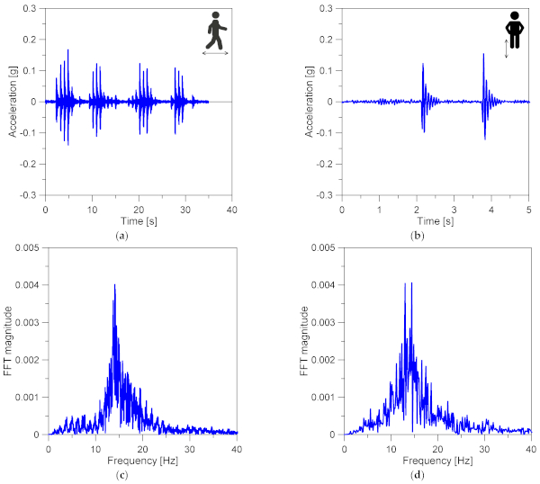
The experimental measurements were performed using a single tri-axial Micro Electro-Mechanical System (MEMS) accelerometer [35]. The experimental program was deliberately focused on selected LG + AN modules as in Figure 5 and Figure 6 with similar global dimensions and boundaries, so that a direct experimental comparative analysis could be carried out. In this context, a single occupant (M = 80 kg) was invited to take part in measurements on LGU and LGF modules. Output-only test data were collected under the effects of normal walks (Figure 7a) or in-place jumps (Figure 7b). The overall experimental analysis included different configurations/repetitions on the two tested modules (18 for LGF and 14 for LGU, respectively). Basically, due to limited size of each LG + AN module, these configurations included linear walking paths along the mid-line, the side-line or cross path. In-place jumps were also made at the centre of panels. A single MEMS sensor was thus repeatedly moved on the slab, so as to capture the acceleration time histories from control points #1 to #5 schematized in Figure 5c. The typical record was characterized by a maximum duration of ≈2 min. Figure 7c,d) show selected examples of FFT signals from vertical accelerations.
4.3. Analysis of Experimental Results
The experimental measurements were post-processed and analysed with the support of SMIT Toolsuite [36], in order to detect the fundamental vibration parameters of the structural object of study. The test setup and experimental protocol was in fact optimized based on the investigation discussed in [33,34], where some LG modular units of the case-study walkway have been previously explored. In the post-processing stage, the ERA-OKID-OO approach was used [37,38].
The experimental records resulted in fundamental vibration frequencies (f1) in accordance with Figure 8. The experimental estimates are proposed as a function of the corresponding vertical acceleration peaks (Figure 8a), or as average terms for the investigated LGF and LGU modular units (Figure 8b). For the reference test setup, the vertical acceleration peak was measured in the range of 0.025 g minimum and up to 0.394 g. The average acceleration peak for the LGF and LGU modules was measured in 0.136 g (±0.059 g) and 0.114 g (±0.080 g) respectively.
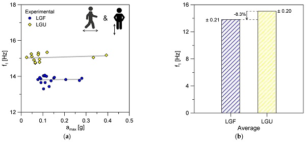
It is worth noting in Figure 8a, for the explored acceleration range, the high sensitivity and lower vibration frequency of LGF estimates to various waking conditions compared to LGU. The average frequency of LGF and LGU modules was calculated in f1 = 13.8 Hz (±0.21 Hz) and f1 = 15.05 Hz (±0.2 Hz), respectively. In this regard, it is clear that a direct quantitative comparison cannot be discussed in general terms for the in-service LG + AN modules object of study, due to possible minor uncertainties in material properties or restraint detailing. In any case, the experimental frequency scatter in Figure 8b can be quantified at about an −8.3% decrease (and thus bending stiffness) for the LGF module, which could be representative of an approximate damage index for the walkway object of study.
5. Frequency Numerical Analysis
5.1. Modelling
The numerical investigation of the walkway module was carried out in ABAQUS [39], in the form of a set of parametric “frequency” analyses aimed at predicting the fundamental frequency and vibration shape of the structural systems object of study. Special care was taken for the inverse derivation of the equivalent MoE for the top fractured layer of glass, Efg. In doing so, the reference FE numerical model was described based on nominal geometrical and mechanical properties of the system, but also based on the extended calibration of model details that was derived from earlier studies in [33,34].
A set of “composite” shell elements (S4R type) was used for the cross-section of the LG plate (3 × 12 mm glass layers and 2 × 0.76 mm PVB foils) and the sustained AN cover, both for the unfractured (LGU) or fractured (LGF) modular units. The AN glass plate was taken into account as an additional monolithic shell layer (6 mm in thickness) placed within the “composite” shell. To facilitate the frequency calculation of the so assembled system, a thin/soft layer was introduced in-between, so as to account for the actual contact interaction of LG + AN glass member. The final result consisted of a seven-ply shell representative of the LG section (three glass layers + two PVB foils), the top AN cover (1) and the interposed soft bonding layer (1). Beam elements (B31 type) were then used for the steel tendons, to account for their nominal circular section (10 mm the diameter). The typical FE assembly was discretized with a regular mesh pattern having an average edge size of 40 mm.
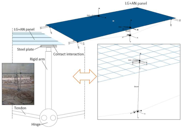
The MEMS sensor was mechanically described in the form of a small lumped mass (Ms = 0.136 Kg its weight) rigidly connected to the top AN panel, and positioned as from the experimental setup. An additional lumped mass (M = 80 kg) was rigidly fixed to glass, and positioned as for the standing occupant during the experimental program (i.e., centre of panel). In this regard, no walking features were taken into account for preliminary frequency estimates. The final FE assembly in Figure 9 consisted in ≈2000 elements and ≈11,000 degrees of freedom.
5.2. Boundaries and Mechanical Interactions
The FE system was linearly supported via distributed nodal restraints for the shell elements composing the LG + AN composite system. The mono-dimensional steel tendons were then pinned at their ends, so as to reproduce their actual mechanical restraint.
For the point supports at the mid-section of each LG panel, a unilateral contact interaction was defined for each restraint, via combined “slot and rotation” connectors. The effect was to reproduce a mechanical support able to carry on compressive loads only, but allowing free relative displacements and rotations at the steel-to-LG interface when subjected to tensile/separation loads. Based on an additional “coupling” constraint, such a nodal effect of the coupled mechanical connector was properly distributed onto the whole surface of steel circular plates in Figure 9 (3 mm their thickness, 40 mm the diameter).
5.3. Material Properties
Linear elastic constitutive laws were used for steel, glass and interlayer foils, based on nominal mechanical features and earlier experimental studies discussed in [33,34] for similar modular units of the investigated walkway. The calibrated input values are summarized in Table 2. Regarding the actual LG + AN contact interaction, finally, the shear flexible bond was defined in the form of a fictitious linear elastic material (ESOFT = 1 MPa). A major support for the calibration of PVB bonding layers was taken from the in-service conditions of the studied system, as also discussed in [33,34], and thus facilitating the vibration analysis of the in-service walkway.
Table 2. Input material properties for parametric frequency estimates with the LGF model.
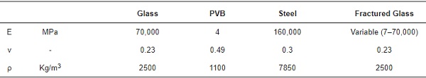
For the LGF module with a fractured glass layer on the top of the LG section, a linear elastic isotropic mechanical model was still taken into account as in Section 3.3. The equivalent MoE was numerically calculated based on inverse techniques, by taking advantage of experimental frequency estimates. To this aim, Efg was iteratively modified in the range from Efg = E = 70 GPa (LGU) and reduced down to Efg = E/10,000 = 7 MPa.
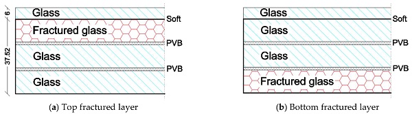
Through the comparative numerical analysis, the reference FE model was described with cross-section features schematized in Figure 10a, that is damage on the mainly compressed side of the LG section, under the effects of sustained vertical loads from pedestrians. For comparative purposes, additional frequency calculations were carried out with a similar FE assembly in which the fractured glass layer was moved to the middle or bottom glass layer, respectively, for the LG section (i.e., Figure 10b).
5.4. Discussion of Results
The typical fundamental vibration shape of the LGU and LGF modules was observed to agree with Figure 11a, that is a simply supported composite section in bending. Given that the fractured LG layer was numerically taken into account in the form of homogeneous equivalent mechanical properties, no modifications were in fact generally observed in terms of curvature or shape amplitude from Figure 11.
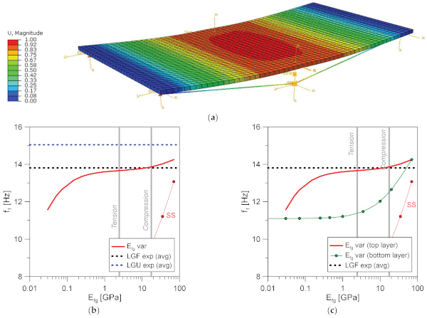
Moreover, major variations were found to manifest in terms of fundamental frequency of the system, as a function of fracture magnitude. Figure 11b shows the fundamental frequency trend for the reference FE model (LGF) when Efg progressively modifies for the fractured layer. As in Section 3, the calibrated tensile and compressive MoE values from [5] are also emphasized. Furthermore, the “SS” frequency estimates described in Section 3 for the simply supported triple LG panel are recalled. Finally, the average experimental frequencies for LGU or LFG modular units are reported. It is worth noting in Figure 11b the severity of vibration frequency decrease when Efg decreases for the single LG top layer. At the lower bound (i.e., null stiffness contribution), a frequency shift of about ≈−25% can be calculated compared to the upper limit condition (LGU).
Regarding the comparative analysis of numerical and average LGF experimental data, the FE model estimates in Figure 11b show a rather smooth frequency variation in the range Efg ≈ 1–20 GPa. A close match of equivalent compressive MoE from [5] can be perceived in this range, with corresponding FE outcomes and average experimental data. This is in line with expectations, given that the top LG layer for the modular unit in Figure 6 under sustained vertical loads is expected to mainly contribute with compressive bending behaviour. Compared to the upper LGU condition, calibrated MoE in compression numerically occurs in a ≈5.5% of frequency drop. The equivalent MoE in tension, conversely, has a minor effect compared to expectations (due to the LG + AN layout and fracture on the compressive side) and results in a frequency drop down to ≈9.2%. Finally, it is possible to notice in Figure 11b that the numerical LGF fundamental frequency is still markedly higher than the “SS” simple boundary condition, due to major modifications in restraints (i.e., mid-span point supports), layout (top AN cover plate) and overall mass properties.
As far as Figure 11c is concerned and attention is focused on the frequency variation with damage layout for the developed LGF numerical model, some additional relevant outcomes can be derived. It is possible to see that the position of fractured layer (i.e., top or bottom layer for the LG section) for the examined geometry can also severely affect the vibration performance of the explored structural system. The shift of the fictious homogeneous fracture from the top FT glass panel to the bottom layer of the LG section (i.e., subjected to major tensile bending stresses under sustained vertical loads) shows a more pronounced sensitivity to fracture magnitude (i.e., Efg). When the bottom fractured layer is fully disregarded in terms of residual stiffness contribution, the frequency decrease can be estimated in a drop of ≈−25% the LGU top limit. The effect of the equivalent MoE in tension from [5], in this regard, is very close to a ≈−25% drop for the numerical vibration frequency. Such numerical findings may be justified by the composite layout for the currently explored glass slab, and thus suggest additional experimental and numerical investigations in this direction. It can in fact be reasonably hypnotized that the top AN cover is able offer a certain stiffening contribution to the top fractured glass layer, which is not the case for the LG + AN section when the fracture moves on the bottom LG side.
In any case, the present comparative analysis also suggests that the use of isotropic equivalent MoE values for fractured glass can support the definition of simplified numerical calculations that are close to the actual behaviour of real LG structural elements with partial damage. Furthermore, the present investigation confirms that simple frequency considerations, even if not exhaustive, can be used for early monitoring purposes and mechanical characterization of materials and components of typical use for structural glass applications.
6. Conclusions
The post-breakage performance assessment of structural glass elements is an open research issues for design, in the same way of vibration serviceability issues for pedestrian glass systems subjected to various operational conditions and influencing parameters. Due to the intrinsic material properties, boundary conditions and operational configurations for laminated glass (LG) elements, a multitude of aspects should be considered. At the same time, the post-breakage stage of LG members is commonly characterized by a combination of additional complex phenomena, which are generally taken into account with simple calculation methods for safe design purposes.
In the present study, attention was focused on the vibration analysis of in-service LG modular elements belonging to a case-study pedestrian system in Italy, affected by partial fracture of the constituent glass components and subjected to ordinary walking loads.
By taking advantage of classical non-destructive experimental approaches, dynamic identification techniques and finite element (FE) numerical models, the vibration response of the case-study fractured walkway module was explored. Special attention was given to fundamental frequency estimates, given that they represent a preliminary but still rather exhaustive parameter for structural health monitoring and early maintenance purposes. As shown, based also on previous literature efforts, the use of an equivalent isotropic modulus of elasticity for fractured glass can represent an efficient tool for the reliable structural design and analysis of LG elements in the post-breakage stage. At the same time, however, additional parameters and complex phenomena should be properly taken into account when the post-breakage performance assessment is applied to pedestrian LG elements (sustained mass, walking features, etc.). In this regard, the present experimental and numerical analysis proved that a simple frequency analysis can represent a first useful step for damage quantification, design considerations and prompt maintenance interventions in LG structural applications. Moreover, future studies will be also focused on multiple case-study systems with different fracture configurations and several walking conditions.
Author Contributions
Conceptualization, methodology, software, validation, and formal analysis: C.B.; data curation, methodology and writing—original draft preparation: C.B. and S.N. All authors have read and agreed to the published version of the manuscript.
Funding
This research received no external funding.
Data Availability Statement
Data will be available upon request.
Acknowledgments
So.Co.Ba. is acknowledged for support during the experimental program.
Conflicts of Interest
The authors declare no conflict of interest.