")
First presented at GPD 2017
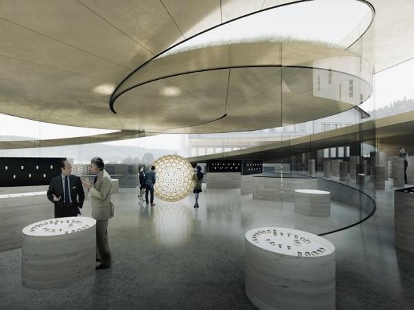
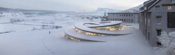
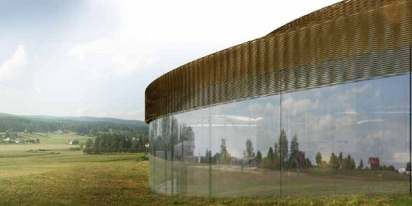
BIG-Bjarke Ingels Group won the competition for the design of the museum in 2015. The design is based on interlocking spirals formed by glass walls evolving out of the rough, natural landscape. The spirals provide a perfect linear museum path for the building program.
Despite the severe loading and weather conditions and inspired by the high values of Audemars Piguet, the project team designed the building to the limtis of what is technically possible. The curved and very large insulated façade glass units, as well as the curved glass partition walls of the interlocking glass spiral are forming the load bearing structure. All vertical and horizontal loads are transferred by these glass components making solid columns and shear wall obsolete.
The article reflects the close collaboration of the designers, engineers, specialist contractor and industry. The global structural concept, transfer of the concentrated point loading into the curved structural glass elements as well as the structural bonding beyond standards and the context of energy efficiency are discussed and elaborated.
Introduction
During 2013 Audemars Piguet launched an invited competition for a watch museum in Le Brassus, Switzerland. The competition team headed by BIG – Bjarke Ingels Group developed the successful project proposal in an intense, interacting design process. The design team focused on creating a building for Audemars Piguet, which is reflecting the company’s values, refereeing to the past and to the future as well as to strengthen the brand with an iconic, sculptural like building close to an architectural emblem. Many options and solutions have been investigated. Finally, the interlocking spiral has been created. The onestory tall spiral is located at the north side of the historical founders building and is directly linked to the new founder’s hall, which is positioned between the existing buildings.
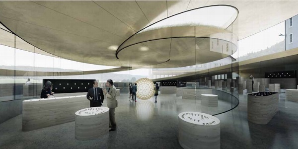
The geometrically very strong spiral is providing a perfect linear museum path along the company’s history as well as watches, and shows a clear analogy to the mechanic of a mechanical watch. Workshops and workplaces of the company’s best watchmakers are positioned along this museum path.
The materials and structural elements are reduced to the essentials. Glass, brass and cast stone are the predominantly, visually used materials.
Structurally, the lightweight roof is supported only by glass elements for the vertical and horizontal loading. This dematerialized glass structure ensures full transparency throughout the building and façade.
The development from the competition project throughout to the execution phase has been subject to many challenges, such as structural robustness, enhanced durability as well as energy efficiency and sustainability.
Project Fundamentals and Design Process
The essential and most important parameter of the project is the shared vision to create the aspired load bearing all glass structure. This vision has been the base of the successful, interdisciplinary design process. A process, that has been exposed to conflicting parameters and focuses. But exactly the constant work on these parameters is the base of the current, successful execution. It is the execution of a carefully developed and enhanced competition project, preserving the original DNA of the design intend.
Due to the location in the Vallée de Joux with the particular, harsh micro climatic condition, the building is exposed to high snow loads above 5 kN/m2, even doubling locally, and very cold temperatures well below -20°C. Sustainability and energy efficiency are imperative design values. Audemars Piguet enhanced these values with a strong commitment to satisfy the Minergie label as minimum.
Minergie is a very common Swiss label rating the energy efficiency but paying attention to the user comfort additionally. These main design drivers illustrate the design challenges. The building structure, formed by the glass elements, have to carry severe loading, and be highly insulated glass walls with premium optical performance. Furthermore, solar control devices have to be implemented to prevent overheating during the warm seasons.
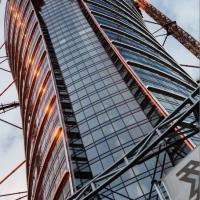
All these objectives are literally wrapped up by an absolute transparent, crisp all glass façade. Triple glazed units (IGUs) are forming the weather skin, providing the water tightness, low air permeability and the thermal insulation. The inner leaves of these triple glazed units are activated as loadbearing elements, proving the vertical and horizontal structural capacity. As an additional element, a brass curtain shades the façade passively but never interfering with eye vision and therefore maintaining the full visual transparency. This brass curtain, a three-dimensional net of individually shaped weaves, is hung above eye level in front of the upper area of the glazing, providing just enough solar protection for comfort and required energy efficiency.
The outlined design shows very well how the best solution was developed on these most important building parts and components, satisfying all major parameters. Iterative design steps, constant testing and improving and a dialogue of the designers and engineers based on expertise have been the key factors.
Material and surface qualities The materialization, respectively the dematerialization is an important part of the project specific design language. The materialization aims for real, raw materials. Materials, that enhance in beauty by aging and building up a natural patina. Untreated brass has been chosen for the visual components such as sun shades and cladding parts, for example cover of roof edge, slabs etc. At the opening, these components will be shiny but darken in different grades due to the natural patina. This patina is a great material characteristic, reducing cleaning demands but also creating esthetic qualities.
The dematerialization depends very much on the glass surface qualities. Surface flaws, such as surface anisotropies and visual distortions, eliminate the aspired dematerialization and transparency. Instead of the visually desired “nothing”, visual errors “kill” the transparency and lead to a surface spiked with visual errors. Technically, these surface flaws or errors belong to the characteristic of processed glass and are mostly subject to thermally introduced surface stresses. Furthermore, the typical total reflection of glass at a particular viewing angle and mirror effect of the applied low e-coating work against the transparency.
Therefore, the dematerialization and transparency are partially opposed by physical laws. Taking on the challenge to get as close as possible to the wanted appearance, the following parameters have been subject to a challenging development. Firstly, the g-value had to be optimized in accordance to the passive shading devices described above. A g-value of 23% proved to be the upper limit in order to avoid the overheating of the building. Esthetically, the low g-values has been a not negotiable value and had to be accepted, as the passive shading devices should not have been extended in the area. Despite this low value, the samples and the first manufactured units show a nice appearance.
The more challenging issue has been to tackle the surface errors. From an engineering point of view, the thermally introduced stresses are used to strengthen the glass. Fully toughened or heat strengthened glass provides a higher load bearing capacity. Furthermore, the risk of failure due to thermally introduced stresses during service is obsolete.
Optimizing the glass towards the annealed state (float condition) with the best possible surface condition requires a careful consideration of the loadbearing capacity under long term loading condition. Additionally, the risk of thermal breakage during service has been assessed carefully, taking into account the interface details, climatic exposure, the applied low e-coating, etc. The decision to use annealed glass on all layers in the triple glazing influenced the bending method fundamentally.
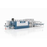
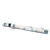
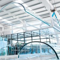
Hot (roller) bending and lamination bending had to be eliminated as a processing option due to the introduced and, in case of the lamination bending, also required thermal stresses, respectively strengthening. Slump or gravity bending is the used bending method, ensuring the best possible annealed surface condition. The first assembled and inspected glass units prove to have an excellent appearance and are achieving the very much aspired and promised transparency.
Thermal concept
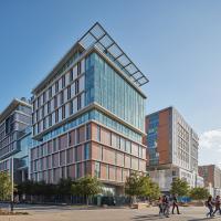
The thermal concept of the façade and glazing is predominately defined by the Minegie criteria. The described exterior passive sun shades and the low g-value of 23% of the glazing is satisfying the energy demands in summer case and prevent overheating. The low u-value of 0.6 W/(m2 K) in conjunction with heaters below the glazing ensures the user comfort, avoiding any down drift during the cold seasons. The energy demands in the winter case are within the set limits. The large, glazed areas are compensated by the highly insulated green roofs. Additionally, photovoltaics on the adjacent existing building are contributing to the strict overall energy assessments and good rating.
Overall structural concept
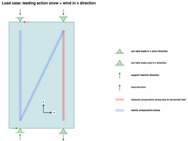
The transparent design of the spiral did not allow placing columns or even walls inside the building. Therefore, it was decided to find a solution with load bearing glass walls. The façade as well as the interior separation walls would be used to transfer the vertical loads (dead load of the roof construction, snow load) and also the horizontal loads (wind load, seismic load). The horizontal loads have to be transferred through the rigid roof construction to the roof edge, from there as in-plane forces through the glass and eventually into the concrete foundation.
Individual glass pane
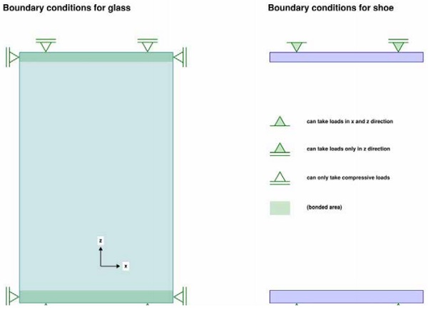
The concept for the individual glass panes was designed as simple as possible. At the outer façade, where the IGU is carrying the loads, the innermost layer of the IGU acts as the loadbearing layer. The loadbearing glass consists of a three times laminated 12mm annealed glass with a SGP interlayer. The glass is bordered at the top and bottom edge with a steel shoe, that is bonded to the glass.
The shoe transfers horizontal in-pane loads to the vertical edge of the glass and from there diagonally through the glass to the bottom support. The vertical loads are being transferred from the roof bracket directly through the steel shoe into the glass. The connection between the bracket and the shoe is only pinned. This ensures that bending moments are not being transferred from the roof into the glass pane. The outer layers of the IGUs are only being supported at the bottom.
These supports take the dead load and reduce the permanent stress on the edge sealing, which now only has to carry the wind loads. The bearing concept of the inner glasses is exactly the same. Due to the larger forces in the centre of the spiral, the glass build-up increases to a maximum of five times 12mm annealed glass.
Design specialities
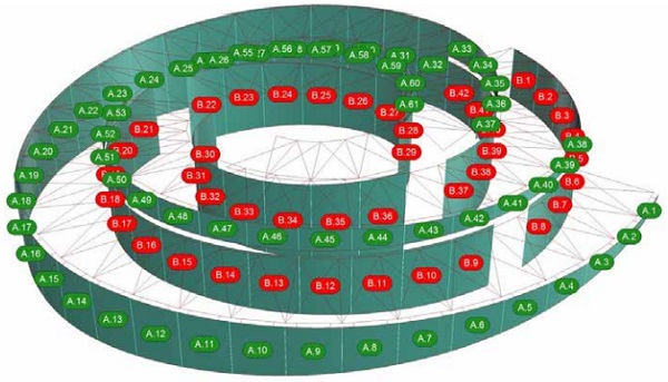
Geometry: The main part of the building consists of two spirals rotating in opposite direction, that interlock in the centre. The way it was designed, only four different glass radii exist. This reduces the expenses of the formwork for the slump bent glasses significantly. The shape of the glasses is, however, always unique. The upper edge of the façade follows the design of the roof edge. The roof edge was designed in consideration of a consistent overall geometry as well as proper drainage paths.
Durability: Since the façade is the thermal envelope as well as a structural element in one, the durability of it became more relevant than usual. It is very important that as little moisture as possible passes through the edge seal. Additionally, the climatic loads in the cavity of a bended IGU cause higher stresses on the edge seal due to the higher stiffness of the glass. Typical IGU’s are being tested for its durability with artificial aging procedures.
Redundancy: The brittle material behaviour of the glass calls for a certain redundancy in the load bearing structure. Although the use of annealed glass in the laminated glass does provide quite a high residual carrying capacity, different load cases with damaged glass plies have been defined for the analysis. Glass panes with one or two damaged glass plies are being calculated as well as the failure of an entire element.
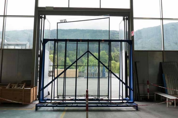
Testing: Many design relevant details and structures with structural glass are not standardized. The few reference projects with similar structures served as an indication during the design phases. Nonetheless, additional testing was unavoidable. The load transfer from the shoe into the glass had already been tested in the design phase. This gave a certain security for the planners to continue with the all-glass design. Further tests, including tests of the IGU and the five times laminated glass, are going to be carried out in the near future with the contractor.
Anchoring of the Glass Units and Structural Bonding
The unique design of La Maison des Fondateurs challenges the engineering of details and solutions. With regard to the top and bottom connections used to retain the curved IG units, a bonded anchoring system is developed beyond stateof-the-art, in order to answer to technical demands outside available Standards. The anchoring system includes clamping profiles bonded to the glass edges by structural silicone Sikasil SG-500 (Refer to figure 4) and is designed to overcome the following challenges:
Design Loads
Due to the curve shape, the severe vertical and horizontal loads applied to the glass components -representing the load bearing structure of the building- are converted into inplane and out-of-plane reaction forces at the bonded connections.
From a structural point of view, the use of an elastic adhesive is ideal to transfer in-plane forces and redistribute them uniformly, without preventing differential thermal dilatation between glass and metallic support. Indeed, any alternative mechanical shear solution (e.g. boring holes through the glass or contact elements) would be critical limiting free dilatations and creating uncontrolled stress peaks into the system.
Compared to typical Structural Sealant Glazing (SSG) systems, where joints are mainly used in tension, embedding the glass panels into clamping profiles allows to maximize the available shear area and convert the out-ofplane reactions into contact compression forces on glass and adhesive. This allows to minimize the SG-joint dimensions while exploiting the compression behavior of the structural silicone Sikasil SG-500. For comparison, Figure 8 and 9 provide behavior of a linear joint (50mm x 12mm x 12mm) tested in tension and behavior of a circular joint portion (D=46mm, H=20mm) loaded by unconfined compression respectively.
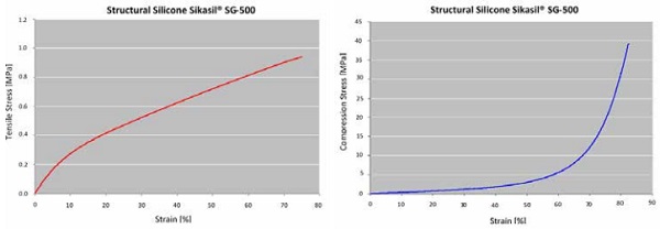
Figure 9 (right): Unconfined compressive behaviour of Sikasil SG-500
SSG-Joints Life Expectancy
A 50-year life expectancy for the designed SSG system is required. This is beyond provisions given by EOTA ETAG002, which regulates SSG performances based on a design life expectancy of 25 years.
As a part of the concept set by EOTA ETAG002 for a 25-year life expectancy, it requires to test adhesion on original project substrates exposing them to artificial aging of 7 days at 23° C / 50% r.h. and 35 days of water immersion at 45° C.
For the project target of 50-year life expectancy, adhesion tests on the original project substrates are performed based on prolonged artificial aging consisting of 7 days at 23°C / 50% r.h. and 70 days of water immersion at 45° C. Test results confirm the excellent adhesion of Sikasil SG-500 on the substrates, if they are preliminarily grinded, pretreated by Sika Aktivator-205 and primed by Sika Primer-210.
Aforementioned adhesion tests are a precondition to release SSG-joints for extended life expectancy. However, the following additional project requirements must also be met:
- The load bearing concept for the whole façade must be designed for 50-year life expectancy;
- The design of the façade has to fulfill all other requirements of EOTA ETAG002;
- A working life time of 50 years must be granted for the substrates, including surface stability;
- Adhesive application must occur in factory and must comply with Sika guidelines and recommended production quality control schemes;
- The place of installation must be carefully checked and limitations may apply (e.g. acid rains, power plants proximity, saltwater, etc. must be excluded).
Materials
Substrates approved by EOTA ETAG002 for structural bonding are stainless steel, anodized aluminum, coated aluminum and glass.
The specific project design requires that the support frames to retain the IG units are composed by galvanized steel plates, with the only exception of stainless steel outer plate used at the bottom connection.
This material selection is implemented to balance project costs and structural needs, while minimizing corrosion risks. As a matter of fact, stainless steel is used where contact to ground and outdoor environmental conditions occur, drainage is more critical and risk of corrosion exists. Galvanized steel is used where exposure to outdoor environmental conditions is excluded and uniform indoor temperatures apply.
In addition to the technical considerations above, galvanized steel can be approved for structural bonding under confirmation that:
- The substrate corrosion protection is adequate to the service life of the bonding joints.
- The coating performances are adequate to the mechanical resistance of the silicone adhesive in the long-term, e.g. the coating must consist in a layer able to transfer loads from the joint to the core metallic substrate.
Adhesive Application
The curing process of 2-component silicones generates by-products that must be released from the joint into air, in order to ensure a proper adhesion build-up. Experimental tests on Sikasil SG-500 show that maximum joint depth must be limited to 50mm to allow a complete by-products elimination, when access to air is limited to one side only of the joint.
Such a limitation is critical for the adhesive application in the project brackets, since design loads require joints up to approx. 200mm.
To overcome the by-product elimination issue, an alternative adhesive application method is recommended; unlike typical SSG application by gap filling from open side, adhesive viscosity of Sikasil SG-500 allows for injection through holes, regularly patterned along the metallic substrate. Brackets can be manufactured with holes drilled at a max. distance of 100mm throughout their height and length. Injection process requires to:
- Start adhesive injection from the first hole.
- When adhesive is visible in the adjacent holes, proceed sequentially with adhesive injection from there.
- Repeat procedure until all gaps between glass and plates are filled in. The visibility of injected adhesive from one hole to the adjacent ones is used as a proof for adequate gap filling.
This bonding procedure allows to compensate easily for manufacturing tolerances of curved parts and to assemble elements in the factory for direct installation, optimizing efforts on site and deglazing procedure.
Project progress
Certainly, the project “La Maison des Fondateurs” will be taken to the GPD 2019 as a completed project and as a museum in service. Currently, the project is in execution. Beside the manufacturing and assembly of the steel and glass element, the bespoke test regime is executed at the Façade and Metal Engineering Center at Lucerne University as well as other test houses. The test regime covers important points such as the extended life span of the triple glazing, load transfer of the concentrated point loads up to 400 kN as well as a full scale ultimate load test . The installation will start in early summer and the building is expected to be water tight by the end of autumn.
Acknowledgement and project partner
Client: Audemars Piguet, Le Brassus
Architecture: BIG - Bjarke Ingels Group, New York
Local Architect: CCHE, Lausanne
Structural Engineering: Lüchinger+Meyer, Zürich
Façade Engineering: Lüchinger+Meyer, Zürich / Lüchinger+Meyer+Hermansen, Copenhagen
Building Physics: Estia, Lausanne
Specialist Façade Contractor: Frener & Reifer, Brixen
Glass Processor: SFL Glastechnik, Stallhofen
Thermal Glass Assessment: concept4glass, Regensburg
Full Scale Testing: Façade and Metal Engineering Center, Lucerne University, Lucerne