Article Information
- Digital Object Identifier (DOI): 10.47982/cgc.8.425
- This article is part of the Challenging Glass Conference Proceedings, Volume 8, 2022, Belis, Bos & Louter (Eds.)
- Published by Challenging Glass, on behalf of the author(s), at Stichting OpenAccess Platforms
- This article is licensed under a Creative Commons Attribution 4.0 International License (CC BY 4.0)
- Copyright © 2022 with the author(s)
Authors:
- Michael Engelmann, Josef Gartner GmbH
- Wulf Wulff, Chair of Hybrid Structures - Structural Concrete, Brandenburg University of Technology
- Thomas Lorenz, Josef Gartner GmbH
- Simon Frey, Josef Gartner GmbH
- Laurenz Wernicke, Control Systems Group, Technische Universität Berlin
- Yangwen Zhang, Chair of Hybrid Structures - Structural Concrete, Brandenburg University of Technology
- Thomas Schauer, Control Systems Group, Technische Universität Berlin
- Achim Bleicher, Chair of Hybrid Structures - Structural Concrete, Brandenburg University of Technology
1. Introduction – Problem and Aim
The taller buildings grow, the more challenging it becomes to cope with forces acting to the structure. This is especially true for dynamic, wind-induced loads that are commonly covered by optimizing the shape of the envelope to reduce turbulences and adapting the structural stiffness accordingly. Additional damping systems allow for a direct influence on the motion characteristics of the building and are numerous in options. To exploit their benefit, the building concept needs to provide
- additional floor space that cannot be commercialized by the building owner,
- dampers of significant mass of several metric tons near the top elevations or•energy for operation of (semi) active devices.
During a joint project, funded by the German Federal Ministry of the Interior and Community, the aim of the project team is to build a full-scale performance mock-up for testing the idea to exploit the available mass already existing in the transparent glass of the building skin for damping.
The original concept of using moveable Double-Skin Facade’s outer skin to reduce structural vibration is proposed by Moon (2009). In Moon's approach, the Double-Skin Facade’s outer skin is perpendicular movable to the building structure. The wind loads are first applied to the movable facade and then transmitted to the building structure through low-stiffness connections. The dynamic wind loads can be isolated from the structure by using these connections. Therefore, structural vibrations are effectively mitigated. However, a fatal disadvantage of this approach is that the efficient structural vibration suppression is always accompanied by severe facade motion, which is practically unacceptable. To overcome this challenge, Moon (2011) first investigated such as distributed tuned mass dampers by adding additional small damping masses in the Double-Skin Facade’s cavity. In a second step, Moon (2016) studied the interaction system of tuned mass damper and Double-Skin Facade damper which combines the concept of perpendicular movable facade with traditional tunedmass damper system. The severe facade motion can be better controlled with these two proposed methods. However,
- both solutions need additional mass,
- the mechanism was not built and verified by reality, even so the theoretical framework showed a considerable potential and
- some unbeneficial effects like disturbance of occupants and impairments of the facade’s ventilation concept were pointed out.
The concept of using parallel movable connections is investigated by the team, which makes it possible that no additional mass is needed. The facade outer skin is fixed in the direction perpendicular to the primary structure, but movable in the direction parallel to the primary structure. The wind-induced structure vibration causes the parallel moveable facades to vibrate, which in turn dampens the structural motion. Upper stories of a high-rise building can be installed with this system to achieve better vibration control performance. This whole system is physically similar as distributed multiple tuned mass damper (d-MTMD) but using existing facade mass as damping mass and makes installation easier due smaller weight per piece. This makes the concept also interesting for retrofitting. In conclusion, we named it distributed multiple tuned facade damping (d-MTFD) system (Zhang 2020).
Other authors focused on numerical calculations finding optimal damping parameters to reduce structural motions during earthquake excitation. (Abtahi et al. 2012; Fu 2013; Fu and Zhang 2016; Barone et al. 2015; Lori 2017; Pipitone et al. 2018). Barone et al. (2015) determined the response during earthquake time-history loading concluding that a reduction compared with the un-dampened case of up to 35 % was a realistic target. Pipitone et al. (2018) also found a reduction of earthquake related motion by activating the mass of a Double-Skin Facade. Finding matching damping parameters, the authors concluded that distributed mass dampers can be customized to react properly versus several critical modes of vibration. However, no structural detailing was proposed to realize a working curtain wall system to verify the theoretical findings. A broader review of the state-of-the-art of vibration control using tuned mass dampers is provided by Rahimi et al. (2020).
Therefore, this paper shows the state-of-the-art in facade design looking into several project case studies. A realistic amount of glass mass is determined as the assumption was made to remain with the existing mass. The carbon footprint of the facade, especially of the glass, will not be changed at this point. From the case study results, structural design details are developed and described whichcomply with the requirements in curtain wall design. A choice was made based on a design assessment and realized in a performance mock-up that was tested experimentally. The paper focuses on the design detailing and finding practical implications. We give an outlook into the upcoming performance evaluation during wind-induced loading. Bridging the gap between computer modelling and full-scale realization is the novel aspect presented in this study.
2.Buildings – Tall and Slender
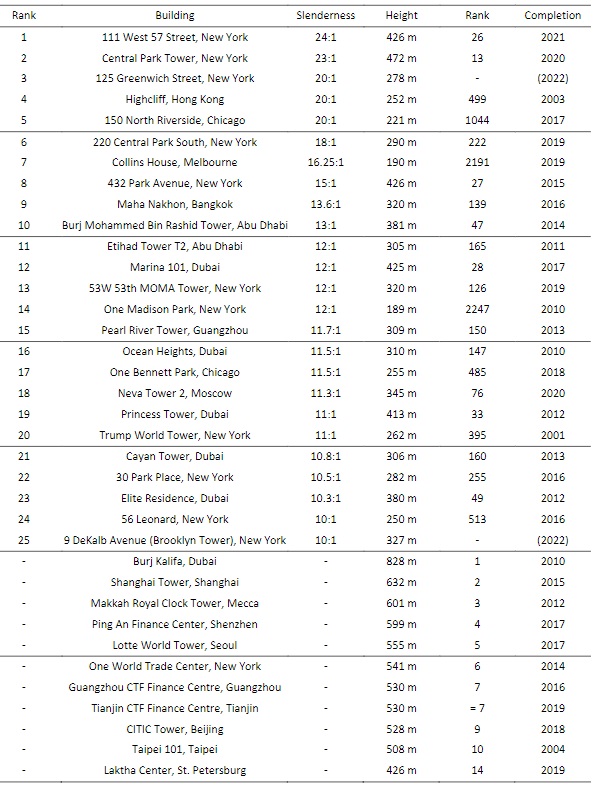
The increasing velocity of developing metropolises is not to be overlooked (CTBUH 2018). New buildings tend to be taller and slenderer (CTBUH 2020). Based on the summary by Szołomicki et al. (2021), Fig. 1 gives a border summary.
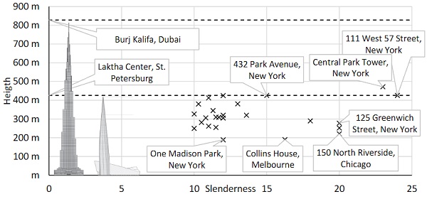
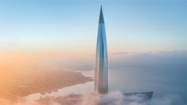
It illustrates that not necessarily the tallest buildings are the slenderest, but the slenderness momentarily climaxes in heights between 472 m (Central Park Tower, New York) and 426 m (111 West 57 Street, New York). These very young towers, completed in 2020 and 2021, will make it to the top 10 tallest buildings as well. This underlines the current trend to exploit a maximum in height while maintaining a small footprint. Also, mostly the United States (13) and Near East (7) are most present while the first tall European building, Laktha Center (St. Petersburg, Fig. 2), finishes at number 14 without making it to the top 25 most slender buildings.
As building height increases, the structural system necessary to withstand wind and earthquake forces in all aspects of design (ultimate load, serviceability and comfort) increases as well. Helal et al. (2020) stated that the embodied greenhouse gas emission per area (NFA) increases. The taller (and potentially slenderer) a building develops, the more efficient the structure needs to be in order to reach the same amount of savings in carbon. This underlines the need for outstanding damping systems in this context.The presented concept aims to contribute optimizing the main structure.
We raise the question: How to exploit the glass mass for damping a building?
3. Facades – Requirements and Projects
3.1. Requirements and Performance
The curtain wall product standard EN 13830 (2020) gives the most comprehensive list of requirements for the facade industry. The data can be generalized for other types of building envelopes. It defines four main features, their respective testing procedures and conformity requirements:
- weather resistance,
- safety in use,
- energy saving and
- thermal insulation.
The results from the presented research aim to extend the performance by adding the un-useddamping potential which requires mass and movement in terms of velocity and acceleration. Therefore, the subsequent sections summarize state-of-the-art facade systems and their available mass.
3.2. Closed-Cavity Facades (CCF)
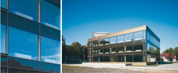
The Closed-Cavity Facade (CCF) is a closed Double-Skin Facade which was developed by Josef Gartner for serial production at the building “InHaus2” of the Fraunhofer Gesellschaft in Duisburg in 2008 (Fig. 3). Down to the present day, it has been implemented to serve sustainable buildings by coveringleading requirements in thermal insulation and sound control. As it can be seen in Table 1, Switzerland, the United Kingdom and Germany are very common markets. However, as the need for increased sustainability grows, this facade solution is also exported to the US market.
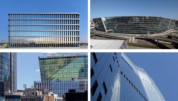
The Closed-Cavity Facade, represented by impressive examples in Fig. 4, is double or triple glazed on the inside and single glazed on the outside. Since the cavity between the inner and outer glazing is completely sealed and protected against weather impact, no pollution occurs that might compromise the blinds and the sun protection. Dry and clean air is constantly fed into the facade cavity in order to prevent condensation on the external glass pane.
This sealed facade cavity is the key technical feature to optimize transparency as well as thermal, sun and sound insulation. Highly transparent, low-iron glazing can be utilized for the CCF. Highly efficient sun protection with sensitive control systems or with light guidance can therefore be installed in the protected facade cavity, which then remains effective in the long-term.
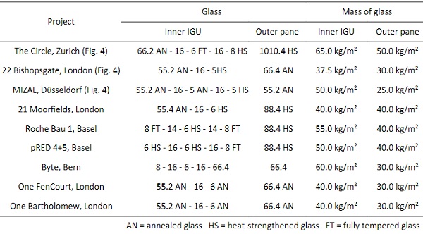
Most mass in a unitized facade system results from the glass. A state-of-the-art Closed-Cavity Facade uses an insulated glass unit on the inside and a single glazing on the outside. Table 1 summarizes exemplary CCF projects with their respective glass mass in main areas. Typically, 25 to 50 kg/m2 can be exploited in the outer pane which accounts for one third to one half of the full glass mass. It should be noted, of course, that the size of the glass is determined by the dimensions of the facade unit and the loading situation.
Table 1: Exemplary Closed-Cavity Facade projects and glass masses.
3.3. Double-Skin Facades
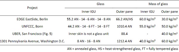
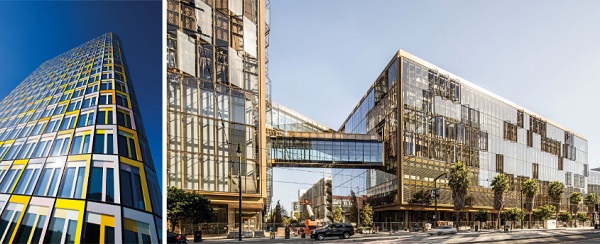
A “Double-Skin Facade” results from an additional glazing which is installed externally in front of the main facade unit (Fig. 5). The created cavity is directly connected to the external air and covers the blind system. Depending on its type of design, performance is target-oriented enhanced. The choice for a Double-Skin Facade improves the light and thermal conditions for internal rooms and reduces the overall energy consumption of the building. This improves the comfort and well-being of the occupant as impairments at air conditioned and conventional workplaces, which can affect the user ́s comfort, are prevented. So the main difference compared with a Closed-Cavity Facade is the airflow between external ambience and the cavity while typical glass layouts and masses remain mostly un-effected as illustrated by examples in Table 2. With this situation in mind, a Double-Skin Facade is an optimal starting point to design a system with a moveable outer skin.
Table 2: Exemplary Double-Skin Facade projects and glass masses.
4. Damping Facade – Structure and Design
4.1. Carbon Footprint
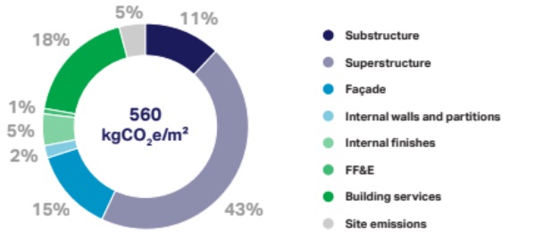
Curtain walls play a major role in the final carbon footprint of a building in both the product stage (embodied carbon, Fig. 6) and use stage (operational energy use). The connector between those two topics is the facade contractor who materializes the demand of the owner in a curtain wall structure. A structural optimization of the framing and the glass as well as the assessment and the optimizationof glazing and sun shading products influence the thermal comfort of the user. Additionally, bringing every component together and sealing it appropriately as well as installing it to the building are critical steps in the process that require a continuous process. As those requirements overlap, a superposition must be defined to find the minimum contribution greenhouse gas emissions. Helal et al. (2020) found that the effect of the facade loads on the embodied greenhouse gas emission of the structural system of a building can be considered minor. However, those results are directly correlated to the dead weight. So every kilogram of dead weight saved in the structural design of the facade has a direct impact on the embodied carbon of the building skin and the main structure. Results by Helal et al. (2020) need to influence the structural design of the curtain wall as aluminum and glass contain considerable embodied carbon.
4.2. Components of the Facade Concept
4.2.1.Structure and Concept
Two different concepts, i.e., perpendicular moveable facade and parallel moveable facade, both have been investigated and proven to be effective in reducing the structural vibration. However, for perpendicular moveable facade, the structural vibration reduction is always accompanied by the severe facade motion, which makes it impossible to implement in practice. Therefore, the approach of using parallel moveable facade is more practical. This final structural concept is well described by Zhang et al. (2021) and Bleicher et al. (2021). For the realized mock-up the following boundary conditions were proposed by the team and can be summarized in few bullet points:
- Minimization of peak acceleration (hotel use according to VDI 2038 (2012-2013)),
- limitation of lateral displacement to ± 500 mm,
- parallel movability of the facade outer skin achieved by using a guide rail system,
- minimum friction (Zhang et al. 2021) and
- manufacturing a single facade unit on a steel building frame that is sliding in a steel base frame. A linear motor is installed to drive the building frame, reproducing the motion of the selected floor under wind excitation.
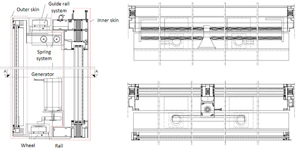
In contrast to other requirements, the focus for optimization is damping performance. This results in a concept scheme printed in Fig. 7 with main components labeled and described in more detail in the subsequent sections.
4.2.2.Fixed Inner Skin with Triple-IGU
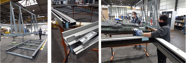
The fixed inner skin of the mock-up is essentially a triple-glazed Single-Skin Facade unit which complies with basic performance criteria of the building envelope. Typical aluminum profiles (EN AW 6060-T66) with E6 C0 (20μm) anodized surface were produced to create two main mullions, 2848 mm in length, a bottom and top transom as well as an additional center mullion splitting the full inner surface in two areas. Thermal separation between outside and inside ambience is realized by polyamide thermalbreaks and a low-e coated triple-I GU filled with argon. As the glazed outer surface was maximized to create the most transparent design, the inner pane is made from a laminated glass section to comply with common demands of human impacts on the glass. Silicone gaskets between glass and aluminum frame prevent penetration of water and allow for an air-tight sealing of the inner space. The assemblyprocedure is documented by Fig. 8.
As most of the components of the moveable part are situated in the cavity they need to be accessible via openable windows instead of fixed glass. Those are necessary for maintenance and repairs as well as for cleaning during the service life of the structure. This will be addressed in detail during a project.
The key feature of the fixed inner skin is the connection elements to the building. To transfer the considerable dead weight to the brackets, stainless steel inserts are fed through the top transom and connected to the pedestals for the wheels. In conclusion, the fixed skin covers the basic demands of a building user not being compromised by the novel system.
4.2.3.Moveable Outer Skin with Laminated Glass
The moveable frame carrying the laminated glass (1010.4 AN, 2583 mm x 2650 mm) is the part of the mock-up that travels as the building is exposed to wind induced vibration and other types of forced motions. Even so it is designed to let air flow into and out of the cavity, it will protect the blind system and the internal guide rail system as well as the components of the damper system. It is critical to reduce the friction of the guide rail system to a minimum. Therefore, the protection is also considered to reduce any un-beneficial contamination of the cavity.
In total, the 2.8 m by 2.6 m frame weights 88 kg/m2. The result is above the average weight as listed in Table 1 and Table 2. The aim to mobilize a maximum of glass weight was extended by additionally mobilizing the aluminum frame and the steel guide rail system. The result is considered a perfect compromise between dead weight mobilized for motion and facade performance. A sustainable contribution to the result is justified by the choice of rails as described in the next section.
4.2.4.Guide Rail System
Core components of the design are a pair of rails at the bottom and top transom of the moveable part and a set of four wheels fixed to the main facade unit. This option was preferred against two other choices as the rails, including larger dead weight compared with the wheels, were exploited as moving mass. Their orientation was chosen to be bottom up to prevent accumulation of dirt in the motion path. This will allow for minimized friction and maximized long-term stability.
All wheels include large stainless steel rolls to counteract wind forces and a set of smaller rolls, oriented perpendicular to the large rolls at the top transom, to carry the dead weight. In this configuration it was possible to use the rails as hooks to hang the moveable skin close to the connections points to the building (Fig. 9). Also, wheels were located approximately 500 mm off the mullions with a clear distance to allow a motion path of ± 500 mm.
An off-the-shelf wheel system was used that allows for minimized friction while at the same moment are resistant in hot and cold as well as dry and humid climates. Therefore, metal rolls were preferred over plastic rolls or tires. This choice also limits the amount of combustible material and scuffing marks. It was worried about potential noise emission which were however not confirmed. Further testing will be necessary to include effects in a realistic environment and during long-term operation.
The most challenging part of the design was to allow for adaption of manufacturing tolerances. As the wheels and rails were customized for the project, the supporting structure had to allow for adaption. Upwards and downwards tolerances were settled by steel shims below the base plate of the wheels and slotted holes of the steel angles connections to the facade transom. Additionally, the eccentric dead weight of the moveable outer skin resulted in torsion of the structure which was anticipated by superelevating the supports.
4.2.5.Spring and Damper
The lateral motion of the moveable part is counteracted by springs. They ensure the reverse motion. A double-set of four spiral springs, 81 N/mm each, in a symmetrical alignment along the center mullion were included between the top transoms in the cavity. In the center, they were connected to the movable outer skin by an aluminum tube while the other ends were connected to the main mullions via steel plates. This configuration minimizes any impact by eccentric loading.
A lateral relative motion will expand one set of springs while the other set is released. This creates a counter-acting spring force which introduces a reverse acceleration until the movement stops at the largest elongation. In this situation the released degree of freedom allows an unobstructed reverse motion. Its kinetic energy is dissipated by internal friction of the guide rail system and viscous damping force of the motor. Exposition to the ambient air may play a role but was considered negligible in this study. Additionally, the bottom rail holds a toothed rack which is connected by a pinion to translate the lateral motion into rotation that drives a generator. A stepper motor with a customized power electronics serves as generator. This enables an adjustable damping coefficient together with energy harvesting.
4.3. Remarks on the Facade System
After testing a single unit, dissolved out of a full building skin, additional theoretical considerations need to be added.
- A full facade elevation will include setbacks, corners, balconies and roof connections. Therefore, two options were prepared to handle those situations. First, it is recommended to use metal sheets at the corners to cover areas that are not cladded during the movement of the adjacent facade units. These moveable parts are supposed to slide behind the cover sheets. As a second idea, the units to the corner units carry smaller skins glass elements and a fixed glazing part right at the corner to cover the motion path.
- Installation, maintenance and replacement need to be addressed. Therefore, gaskets between floors need to be sized to allow removal and replacement of the outer glass and frame from the outside. Additionally, the cavity needs to be accessible from the inside by operable windows.
- Connections need to be realizable to minimize structural components. This refers to connections between moveable panes in one floor and between floors.Further details are beyond the scope of this study, but will be addressed in the future through call for proposals and building designs that exploit the mass of glass to mitigate the structural vibrations of high-rise buildings.
5. Performance – Expectations and Evaluation
The performance of the full-scale prototype was tested using Hardware in the Loop (HiL) simulation. The prototype works as the hardware part as shown in Fig. 10.
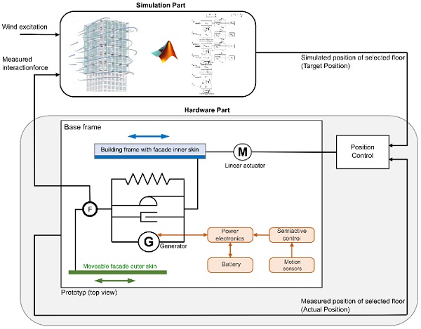
The simulation part is a widely used 76story high benchmark building (Yang 2004) under wind excitation with one missing facade element. The missing facade element in the simulation part is our built prototype. The communication of the simulation part and hardware part is through the linear actuator. It physically reproduces the simulated motion of the selected floor of the benchmark building. Finally, the interaction force between the facade inner skin and outer skin is measured through a force sensor and fed back to the simulation part.
Multi-objective Genetic Algorithm is applied to optimize the whole system looking at two objectives simultaneously:
- The first objective is to reduce the top floor acceleration while
- The second objective is to reduce façade motion in terms of moveable facade relative displacement.
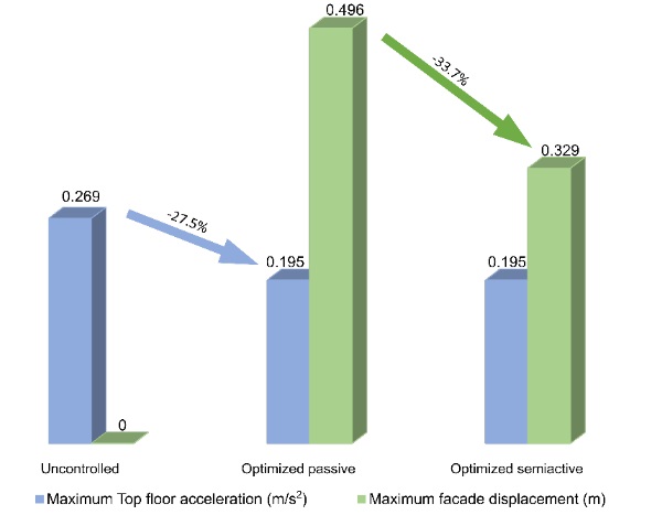
Both, passive and semi-active systems are optimized, and optimized parameters are set for both the simulation part and hardware part for the experimental test. The optimized passive and semi-active systems are compared with the uncontrolled benchmark building as shown in Fig. 11. Both optimized systems can reduce structural vibration by 27.5 %. When using semi-active control, the maximum relative facade displacement can be reduced by 33.7 % compared to the passive system with the same structural vibration performance.
The adjustable damping coefficient in the connection is achieved by the stepper motor together with a specially designed control circuit. The stepper motor functions not only as an adjustable damper, but also as an energy harvester. The dissipated energy can be harvested as electrical energy through the circuit and stored in the battery. This energy can be used to power up the semi-active control. Initial investigation based on the HiL simulations indicate that the totally harvested energy under the considered 10 m wind speed of 13.5 m/s is sufficient to supply the embedded system (microcontroller, sensors and power electronics) of all movable facade elements, which means an autonomous semi-active system can be achieved under this wind condition.
6. Final Remarks – Conclusion and Summary
Building more slender skyscrapers and the urgent need to reach net-zero building industry leads to increasing requirements in design and engineering. A contribution is to mobilize existing mass enclosed in the facade to replace conventional damping systems. As earlier studies showed the potential, this paper describes practical implications of realization a full-scale facade mock-up. After summarizing the state-of-the-art in facade design by a project review, the structural detailing and production is presented and implications as well as alternatives are discussed.
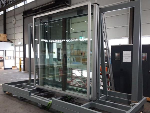
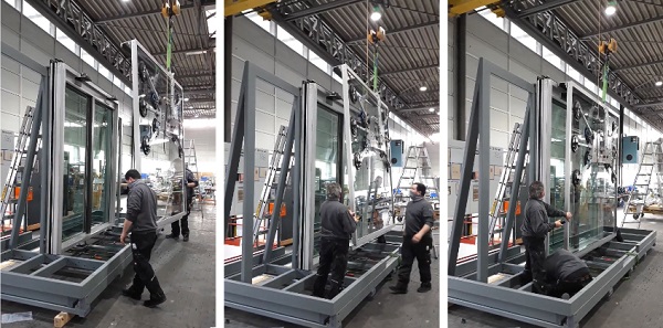
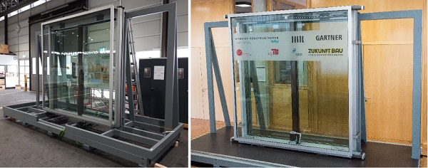
A full-scale performance mock-up was designed and engineered by the project team. Production was running smoothly with several progressive iteration steps and improvements. The mock-up was delivered in time and showed, after full-scale testing, that the principle is applicable in reality (Fig. 12).
Topics such as long-term stability, economic optimization, the thermal performance of the complete system and user acceptance of the movement are certainly topics that come to the mind of the engineer ad hoc and that must be taken into account for an application with certainty.
At the same time, we seek to inspire some architectural design drafts, since such a design will most likely characterize the building and doing so will also shape the skylines of modern metropolises. With this in mind, we ask the creative designers for suggestions and discussion!
References
Abtahi, P., Samali, B., Zobec, M., Ngo, T.: Application of flexible façade systems in reducing the lateral displacement of concrete frames subjected to seismic loads. From Materials to Structures: Advancement through Innovation, 241(2012) http://handle.uws.edu.au:8081/1959.7/541605
Barone, G., Palmeri, A., Khetawat, A.: Passive control of building structures using double-skin façades as vibration absorbers. In Kruis, J., Tsompanakis, Y., & Topping, B.H.V. (Ed.), Proceedings of the Fifteenth International Conference on Civil, Structural and Environmental Engineering Computing, Prague (2015) https://doi.org/10.4203/ccp.108.94
Bleicher, A., Schauer, T., Jirasek, R., Höltke, T., Zhang, Y., Marker, P., Wulff, W., Manfrecola, J., Schmidt, T.: Hybride Konstruktionen an der BTU Cottbus-Senftenberg. Bautechnik, 907 – 920 (2021). https://doi.org/10.1002/bate.202100056 CTBUH. CTBUH Year in Review: Tall Trends of 2018. Chicago, Illinois (2018) https://www.skyscrapercenter.com/year-in -review/2018 [Accessed: 02 Nov 2021]
CTBUH: The Global Impact of 9/11 on Tall Buildings. (2021) https://www.skyscrapercenter.com/9-11-global-impact[Accessed: 02 Nov 2021]
EN 13830: Curtain walling. Product standard. (2020)
Fu, T.: Double skin façades as mass dampers. In: 2013 American Control Conference. (2013)https://doi.org/10.1109/ACC.2013.6580571
Fu, T., Zhang, R.: Integrating Double-Skin Façades and Mass Dampers for Structural Safety and Energy Efficiency. Journal of Architectural Engineering. (2016) https://doi.org/10.1061/(ASCE)AE.1943-5568.0000218
Fu, F.: Design and Analysis of Tall Complex Structures. Elsevier, 1-295 (2018) https://doi.org/10.1016/C2015-0- 06071-3
Helal, J., Stephan, A., Crawford, R. H.: The influence of structural design methods on the embodied greenhouse gas emissions of structural systems for tall buildings. Structures 24 (2020) https://doi.org/10.1016/j.istruc.2020.01.026.
Lo, A.: The slender skyscrapers changing New York’s skyline. https://edition.cnn.com/style/article/new-york-slender-skyscrapers/index.html [Accessed: 02 Nov 2020]
Mehl, R.: Superschlanke Skycraper in New York. https://www.baudokumentation.ch/fachwissen-szene-artikel/projektbericht/superschlanke-skyscraper-in -new-york/41293502 [Accessed: 02 Nov 2020]
Moon, S. K.: Tall Building Motion Control Using Double Skin Façades. Journal of Architectural Engineering (2009-2) https://doi.org/10.1061/(ASCE)1076-0431(2009)15:3(84)
Moon, S. K.: Vertically Distributed Multiple Tuned Mass Dampers in Tall Buildings: Performance Analysis and Preliminary Design. The Structural Design of Tall and Special Buildings. (2009-1) https://doi.org/10.1002/tal.499
Moon, S. K.: Structural Design of Double Skin Facades as Damping Devices for Tall Buildings. Procedia Engineering 14 (2011)http://dx.doi.org/10.1016/j.proeng.2011.07.170
Moon, S. K.: Integrated damping systems for tall buildings: tuned mass damper/double skin facade damping interaction system. The Structural Design of Tall and Special Buildings, (2016) https://doi.org/10.1002/tal.1237
Pipitone, G., Barone, G., Palmeri, A.: Optimal design of double‐skin façades as vibration absorbers. Structural Control and Health Monitoring. (2018) https://doi.org/10.1002/stc.2086
Rahimi, F., Aghayari, R., Samali, B.: Application of tuned mass dampers for structural vibration control: a state-of -the-art review. Civil Engineering Journal (2020) http://dx.doi.org/10.28991/cej-2020-0309157
Schauer, T., Bleicher, A., Zhang, Y., Wulff, W., Wernicke, L.: Energiegewinnung an Doppelfassaden aus Wind induzierten Schwingungen zur aktiven Kontrolle von Bauwerksschwingungen. BBSR-Online-Publikation X/202X, Bonn, Monat Jahr. (in print)
Szołomicki, J., Golasz-Szołomicka, H.: The Modern Trend of Super Slender Residential Buildings, Budownictwo i Architektura 20(1) (2021) https://doi.org/10.35784/bud-arch.2068
Lori, G.: Dynamic Vibration Damping System for High- Rise Buildings. Patent W0/2019/116410, 14.12.2017.
VDI-Richtlinie 2038: Serviceability of structures under dynamic loads - Methods of analysis and evaluation in structural dynamics. Multiple parts. 2012-2013
WBCSD: Net-zero buildings. Where do we stand? (2021)
Yang, J. N., Agrawal, A. K., Samali, B., Wu, J.: Benchmark problem for response control of wind-excited tall buildings. Journal of engineering mechanics, 437-446, 130.4 (2004). https://doi.org/10.1061/(ASCE)0733-9399(2004)130:4(437)
Zhang, Y. , Schauer, T., Wernicke, L., Wulff, W., Bleicher, A.: Facade-Integrated Semi-Active Vibration Control for Wind-Excited Super-Slender Tall Buildings. IFACPapersOnLine 53, Nr. 2, 8395 – 8400 (2020).https://doi.org/10.1016/j.ifacol.2020.12.1585
Zhang, Y., Schauer, T., Wernicke, L., Vrontos, A., Engelmann, M., Wulff, W., Bleicher, A.: Design of Moveable Façade Elements for Energy Harvesting and Vibration Control of Super Slender Tall Buildings under Wind Excitation. Powerskin Conference. Munich (2021) 978-94-6366-406-6
Appendix
Table 3. The 25 most slender and top 10 highest buildings.
Key building data based on Mehl (2020), CTBUH (2021) and Szołomicki et al. (2021)


 demonstrator at Glass Technology Live during Glasstec 2024 (© Cas Maertens).")