The Paper "Free-Form Shape Cold-Bent Structural Silicone Glazed Façades - Design Concept and Challenges" was first presented at GPD 2017 by Benjamin Beer, Technical Director at Meinhardt Façade Technology, Dubai, United Arab Emirates.
The design of the primary and secondary seal structural silicones is however a challenge as no design standards are available; even most of the major silicone suppliers currently do not have clear design guidelines for free-form cold-bent structural silicone glazed facades.
Following up on the previous Glass Performance Days paper by the author with focus on the “single corner cold-bending” [1], this paper focusses on the “free form shape cold-bending” and presents a new design concept for the structural silicone design. In addition, various graphs are shows to provide theoretical background on facade panelisation options, various cold-bending geometries (e.g. spherical, anticlastic and concave/convex freeform), post-cold-bending glass edge rotation and silicone stress models for different coldbending/edge warp modes.
Introduction
After a series of realised projects, the so called “Single Corner Cold-Bending” process (Figure 02) became established within the façade industry to provide better architectural appearance compared to the “Fish Scale” principle (Figure 01).
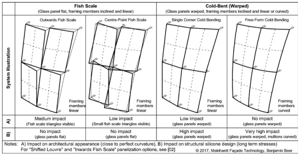
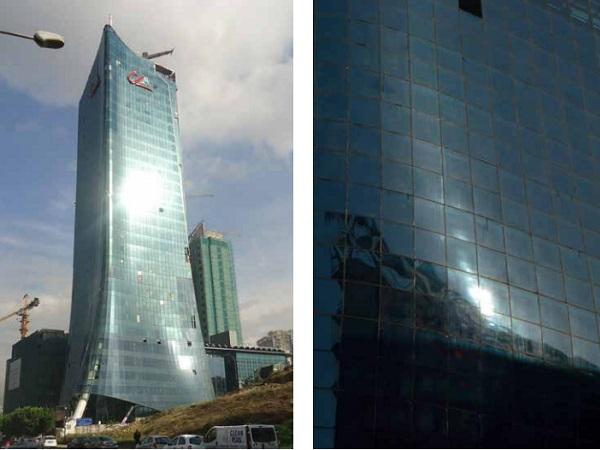
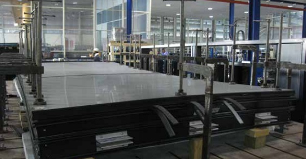
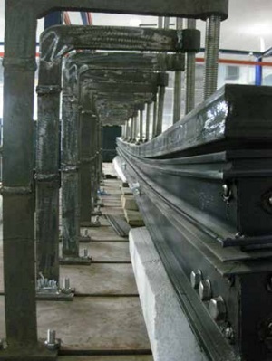
Taking the next step in the cold-bending process, the first facade using the new “Free-Form Cold-Bending” process is currently being installed in Dubai (Figure 03). Comparing to the panelisation options Fish Scale (outwards, centre-point and inwards) and the option Single Corner Cold-Bending” as explained in Figure 01, the Free-Form Cold-Bending option provides the best approximation to a perfectly curved façade – however with the downside of high complexity in the structural silicone design.
When considering the structural silicone design and guidance for a stress based design, both cold-bending processes mentioned above are not covered by national or internal design codes or standards – showing the need for in-depth research and discussions between industry experts.
Whilst the single corner cold-bending process was discussed by the author in previous publication [01], [02] including a proposal for a design concept, this paper focusses on a new structural silicone design concept for free-form shape coldbent facades. This design concept uses a stress approach “FE Stress” (Finite Element Stress) vs. “Engineering Stress”, in which a FE analysis with hyperelastic material constitutive modelling has been implemented for a reference project (Figure 03).

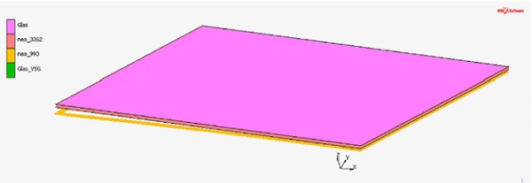
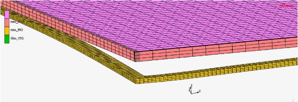
Figure 03 (right): Free-form shape cold-bent structural silicone glazed façades (partially hot bent-glass is used)
Single Corner Cold-Bending vs. Free-Form Cold-Bending
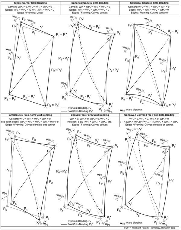
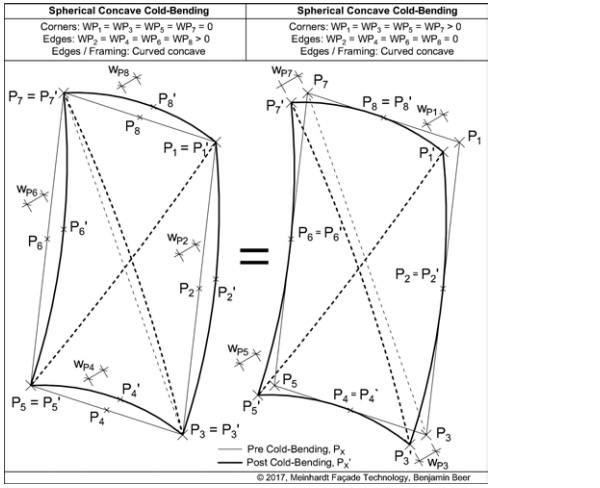
Figure 04 provides an overview of typical cold-bending geometries. The single corner cold-bending is the most common geometry being realised on various projects over the last approximately 10 years. Here, the aluminium framing members are linear and the glass is produced flat. All other cold bending geometries including spherical convex, spherical concave, anticlastic free-form, convex free-form and concave / convex freeform are based on curved framing members. The amount of warp at each corner (P1, P3, P5 and P7), at centre of the edges (P2, P4, P6 and P8) and the relation between the warp data (P1 to P8) defines the cold-bending geometry.
Most cold-bending geometries have an inwards and outwards mode as shown in Figure 05. Swapping in between these two modes can be done by exchanging the warp value of the corner points (P1, P3, P5 and P7) with the warp values of the centre of edges points (P2, P4, P6 and P8). The choice between inwards or outwards mode is usually dictated by the position of the framing members, typically located on the building’s inside.
Cold-Bent Structural Silicone Glazed Facades – Silicone Shear Stresses
The cold-bending process and resulting curvature causes shear deformations between the various layers of the façade panel assembly. The shear deformation is not constant and varies over the width and height of the panel, maximum values can be expected at the points of greatest shear deflections and are defined by the angle of rotation φ. Figure 06 provides system sketches indicating edge warp and edge rotation for the two key locations: corner and mid-edge.
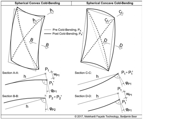
Besides the permanent tensile forces in the structural silicone, the edge rotation angle and resulting permanent shear deformation is one of the key problems when designing cold-bent structural silicone glazed facades. This applies to both structural silicone seals (Figure 07):
A) Primary Seal - between the IGU inner glass pane and aluminium frame
B) Secondary seal - between IGU inner and outer glass pane
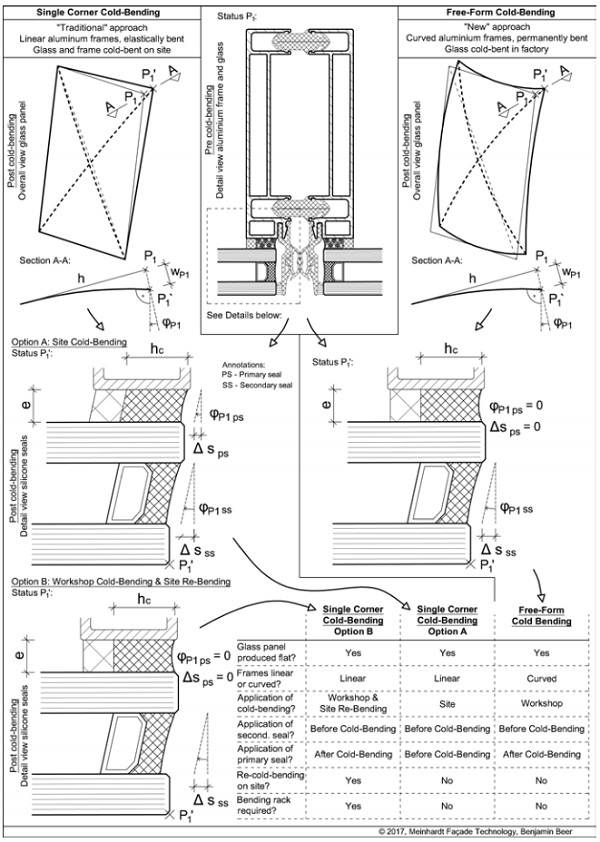
As per [4] and the corresponding European Technical Approval ETA’s for typical two part structural silicones, the allowable long term silicone stress is only 1/10 of the allowable short term silicone stress. In an effort to reduce the silicone primary seal shear stresses for single corner cold-bent facades and firstly used for the Credit Libanais project in Beirut [1], the author developed the method “Workshop Cold-Bending & Site Re-Bending”. A comparison of the two cold-bending options for single corner cold-bending is listed below:
A) Option A - Site cold-bending:
The glass panel and the framing members are produced flat, the structural silicone between glass panel and framing members is applied in the workshop. Once the silicone is cured, the flat façade panel is transported to site and forced into the coldbent geometry during installation to the building’s slab edges.
B) Option B - Workshop cold-bending and site re-bending:
The glass panel and the framing members are produced flat. While still in the workshop, the glass panel and the framing members are forced into the cold-bent geometry using a bending rack. Then the structural silicone between glass and framing member is applied. Once the silicone is cured, the cold-bent façade panel is transported to site in the bending rack. The lifting and installation of the panel requires the panel’s release from the bending rack, for this temporary condition the panel will partially deform back from the cold-bent geometry and silicone shear stresses increase for that moment. The panel fixing to the building’s slab edges will require the site re-cold-bending. After that process, the installation is finished and the silicone shear stresses are back to the postcold-bending normal level.
Figure 07 compares the corner shear deformations and provides an overview table for the single corner cold-bending options A and B, as well as for the mode free-form cold-bending. As mentioned above, the single corner cold-bending option B results in lower shear stresses in the primary seal. Due to the pre-curved framing members used for free-form cold-bending, a similar effect with lower shear stresses in the primary seal is achieved. It shall be noted that for all options, the shear stresses in the secondary seal (between inner and outer glass pane) are not reduced as the insulating glass production is usually before façade panel assembly and cold-bending. An insulating glass unit production with application of the secondary seal structural silicone post-cold-bending might be technically feasible, would however require further research and is does not form part of this paper.
Free-Form Cold-Bent Structural Silicone Glazed Facades – Silicone Tensile Stresses
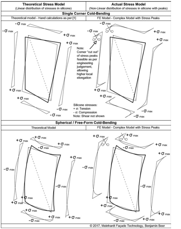
As for the allowable silicone shear stress, also the tensile stress for long term loads can be assumed to 10% of short term allowable stress. Due to the elastic cold-bending process and the glass trying to bend back into its original flat position, permanent (long term) tensile stresses act in the silicone. The distribution of the permanent silicone tensile stresses depends on the coldbending geometry and the method of stress analysis: hand calculations or Finite Element (FE) analysis.
Referring to the output of computational FE analysis and stress peaks often encountered in the results graphs, the evaluation requires substantial expertise and engineering judgement. The stress peaks are often localized in small areas and might be “cut-out” to avoid an overly conservative design - considering that these small overstressed areas will result in a localised higher elongation, which shall be no problem for the overall system. The concept of corner “cut-out” of local stress peaks was presented for single corner cold-bending in [1]. Figure 08 compares the theoretical stress models with actual models, both for single corner cold-bending and free-form shape cold-bending.
Free-Form Cold-Bent Structural Silicone Glazed Façade – Project Example
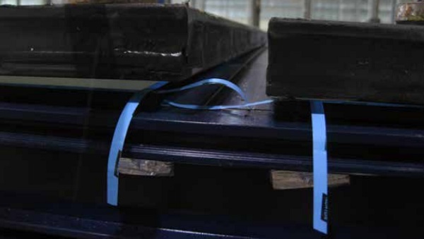
As mentioned in the introduction, the first project using the free-form Cold-Bending process is currently under installation in Dubai (Figure 03). The curved facades use both hot-bent glass and cold-bent glass; the hot-bent glass is used for areas with high curvature where cold-bending limits would have been exceeded. Figure 09 shows the precold-bending status with the open gap (corner warp) between glass and frame. Figures 10 and 11 show photos taken after cold-bending and prior to primary seal structural silicone application.
Engineering Approach for the Structural Silicone Design Concept
Currently no international code or standard covers the structural silicone design of coldbent structural silicone glazed systems. Guidance on the structural silicone design using FE models is given in [5] and [6], where publication [5] presents the concept of True (FE) Stresses vs. Engineering Stresses and emphasizes the importance of deriving a conversion factor between both stresses (also see item B below).
This paper is based on an engineering approach using the following steps:
A. Initial simplified assessment of the structural silicone seals assuming flat glass and flat framing (no cold-bending) using ETAG 002 “Structural Sealant Glazing Systems Part 1: Supported and Unsupported Systems” [4]. This is for initial guidance only an helps to assess the silicone’s capacity available for additional (cold-bending) stresses.
B. Set up and analyse a FE model to simulate the ETAG-002 [4] H-test model already tested by the silicone supplier as per ETA (European Technical Approval). This model acts as a validation model to derive a conversion factor between the true Finite Element (FE) Stress derived from the FE models, and the Engineering Stress as per the allowable design limit stress stated in the ETA of the silicone supplier.
C. Set up and analyse a FE-Model for each free-form shape cold-bent glass panel. The structural models include 3D volume elements of the structural silicone and all loads including long term (e.g. cold-bending) and short term loads (e.g. wind pressure and suction).
D. Assessment of the FE-Stress results and conversion from “FE-Stress” to “Engineering Stress”, result overview using the allowance stress approach as per [4]. Local stress peaks might be assessed using the “corner cut-out” method explained in [1].
H-Test Model to Derive Conversion Factor “Engineering Stress” to “Finite Element Stress”
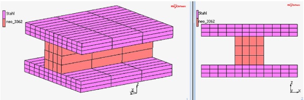
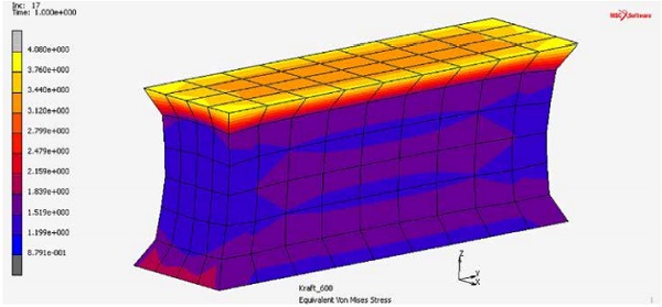
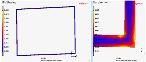
The H-test model FE analysis shall use identical boundary conditions as the laboratory tested H-test specimen as per [4]; the steel plate being 40 mm width, 50 mm length, 5 mm thickness and the silicone being 12 mm width, 12 mm height 50 mm length (Figure 12). These dimensions are in line with ETAG figures [4].
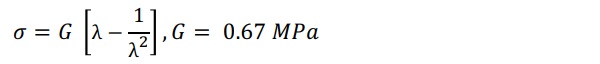
Stresses and strains are derived for this model and compared with the actual test results. This H-test FE model (Figure 12) shall use the same setting (analysis software Marc Mentat 12, setting, FE mesh density, etc.) as the FE models of the complete glass panels being cold-bent (Figure 20, 21). All FE models use shell elements for the glass panes, volume elements for the structural silicone sealants and the Neo-Hook material model for the silicones:
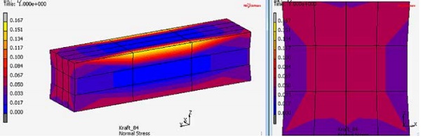
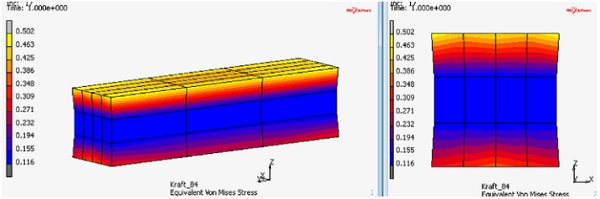
Two load cases were set up to derive the conversion factors for a typical 0.14 N/mm2 silicone stress limit (as per silicone supplier’s ETA), and a silicone overstress of 1.0 N/mm2 (as the engineer’s judgement). See data below:
• Load case 84 N tensile load to derive conversion factor for 0.14 N/mm2 silicone stress:
Face load on upper steel plate:
84 N / (40 mm x 50 mm) = 0.042 N/mm2
Nominal tension stress in silicone:
84 N / (12 mm x 50 mm) = 0.140 N/mm2
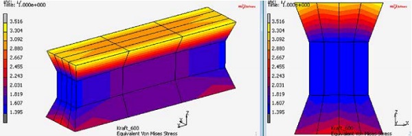
• Load case 600 N tensile load to derive conversion factor for 1.0 N/mm2 silicone stress:
Face load on steel plate:
600 N / (40 mm x 50 mm) = 0.3 N/mm²
Nominal tension stress in silicone:
600 N / (12 mm x 50 mm) = 1.0 N/mm²
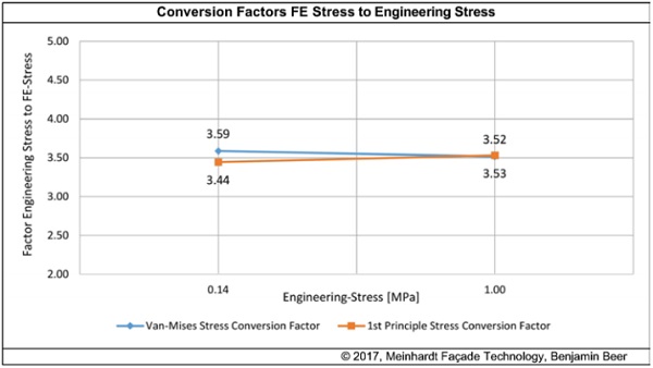
The FE results are shown in Figure 13 to 15. Taking the Van Mises stress output of the load case 84 N and 600 N models, the following conversion factors “Engineering Stress” to “Finite Element Stress” can be derived:
• Load case 84 N (equivalent to 0.14 N/mm2 Engineering Stress): 3.59
• Load case 600 N (equivalent to 1.0 N/mm2 Engineering Stress): 3.52
The above factor of 3.52 and 3.59 depends on the FE software, calculation model, mesh density, stress type used and other items. Therefore, the above conversion factor varies from the factor shown in other publications [5]. It shall also be noted that [5] used the First Principle Stress, whereas the above calculations use the Van-Mises Stress.
Both stresses can be used and the difference in the conversion factors is almost neglectable (Figure 16).
FE Mesh Density
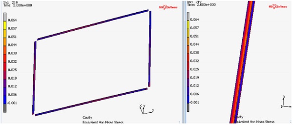
The above H-Test models (Figure 13 to 15) use an identical FE mesh density as the as the actual models of the complete glass panels (Figure 21). This is important as the conversion factor Engineering Stress to FE Stress from the H-Test model will be used for actual calculations. The mesh density of the H-Test models above might be seen as course and not dense enough.
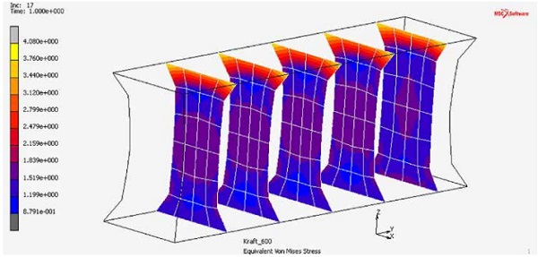
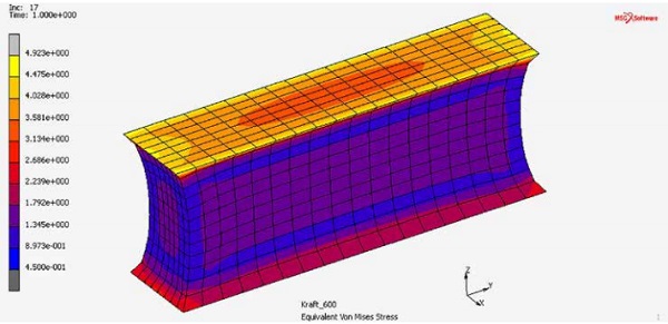
This however should have no effect as the same mesh density is used for the actual calculations of the complete glass panels (Figure 21), nevertheless comparison calculations with higher FE mesh densities were carried out. When comparing the Van Mises stresses of the H-Test model with course mesh (Figure 13 to 15) and the Van Mises stresses of the H-Test model with fine and extra fine mesh (Figure 17 to 19), the difference in maximum Van Mises stress is as follows:
- Standard mesh density (course): 3.53 N/mm²
- Fine mesh density: 4.08 N/mm²
- Extra fine mesh density: 4.92 N/mm²
To keep the computing time within reasonable limits, the actual models of the complete glass panels use the standard mesh. As the H-Test model for calculation of the conversion factor uses the same mesh density, this standard mesh will not lead to significant differences in the stress results and is therefore acceptable.
Full Scale FE Models of Free-Form Cold-Bent Structural Silicone Glazed Panels
The FE models are built in two stages; first the structural sealant with an ideal stiff bent frame (zero deflections under all load cases) and second the planar (flat) insulating glass unit. FE contact elements are placed between the insulating glass unit and structural sealant. The modelling and analysis process involves the following steps:
1. Set up of the initial pre-cold-bending model with curved framing and planar (flat) glass (Figure 20). Generate the FE mesh (Figure 21) with mesh density as per H-test model used to derive the conversion factor “Engineering Stress” to “Finite Element Stress”.
2. The initial model with planar insulating glass is loaded at the edges, the glass is deformed until the edges get in contact with the structural sealant geometry (bent silicon, Figure 22). The contact elements are closed and will be “glued” for the other steps. This step considers that the primary structural silicone is applied after cold-bending of the glass, see also the illustration and table data for free-form cold-bending shown in Figure 07.
3. The edge loads required to achieve contact between the silicone and the curved frame are deleted. All glass elastic cold-bending loads are now transferred via the structural silicone; preventing the glass to bow back into its original flat (planar) geometry.
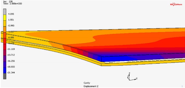
4. Load the model with the climatic loads (isochronic pressure in cavity) based on air pressure (hPa), temperature change in air cavity (°C) and the height difference (m) between glass manufacturer and site location.
5. Add the wind loads.
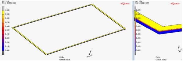
The process of load application at the edges during step 1 is iterative, the load amount and load spacing must be varied up to the status of continuous contact between the silicone and framing at all locations. Some FE programs allow coloured output plots for contact checks (Figure 23).
Evaluation of FE Analysis Stress Outputs
FE analysis stress outputs for the following load cases (item 1 to 4) and load combinations (item 5) shall be checked to evaluate compliance to allowable stress limits:
1. Dead load - Long term load
2. Post-cold-bending (cold-bending forces released) - Long term load
3. Climate loads (isochronic pressure, summer or winter) - Long term load
4. Wind load (pressure or suction) - Short term load
5. Combinations of the above load cases including wind load case – Combination of long and short term loads
Item 5 refers to load combinations including short and long term loads. Here the results evaluation is further complicated by the different stress limits for long term loads and short term loads, where the stress limits for long term loads is usually 1/10 of the limit for short term loads. Due to the nature of the cold-bending process reflected in the steps during FE analysis, the short term load case 4 (wind load) can only be run in conjunction with the long term load case 2 (cold-bending forces released: post-cold-bending).
For this load combination, the FE software provides just one stress plot “merging” the stress results for the long term and short term load case. An “manual” overlay of the short and long term stress data for each FE mesh nodal point can be done, however this complex and time consuming method might not be preferred. Further research will be required to assess the best way how to easily evaluate these load combinations.
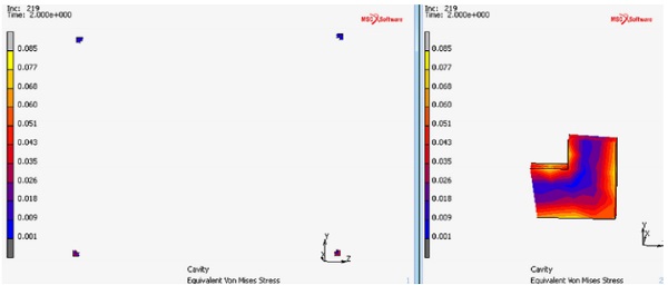
Looking at the overall stress plot for one glass panel, the evaluation of FE results can differentiate between “Overall”, “Peak” and “Non-Peak” areas. For peak areas, the concept of cutting out stress peaks (Figure 08) can be used to avoid an overly conservative design. The definition of extent of corner cut-out requires engineering judgement and experience, as a local silicone overstress will be allowed. In the case of the secondary sealant, acting as the edge seal of insulating glass unit, the local overstress might lead to a locally reduced air tightness of the edge seal.
A typical corner area with stress peaks is shown in Figure 24. Here, the concept of corner cut-out as shown in Figure 25 (nonpeak plot) and in Figure 26 leads to a stress reduction of approx. 25%. Further information on the topic of long term performance of coldbent insulating glass units can be found in [7], although no detailed information on stress limits is provided.
Summary
To achieve a flush and capless outer glass appearance, many complex geometry coldbent façade projects use structural silicone glazing systems to hold the glass panels in place. While this is architecturally a preferred and ideal solution, the façade engineering and structural designer is faced with the problem of long term tensile and shear forces on the structural silicone, caused by the glass intending to reverse the elastic glass coldbending process and forming back to its initial flat position.
This effect is unique to cold-bent facades and different to hot bent glass facades, where the glass bending process causes a permanent (non-elastic) curvature of the glass. Besides the presentation of various graphs for the most common cold-bending geometries and a recommendation for workshop coldbending and site re-bending to reduce structural silicone primary seal shear stresses, a new design concept for the structural silicone design of free-form cold-bent structural silicone glazed panels is presented in this paper. To push this new design concept to an agreed standard within cold-bent façade specialists and silicone suppliers, the author welcomes feedback and technical comments.
Acknowledgements
The author kindly acknowledges Prof. Dr.-Ing. Eva Scheideler (University of Applied Sciences Ostwestfalen-Lippe, Germany) and her engineering office for their support in carrying out the hyperelastic Neo-Hookean material model analysis with MSC Marc Mentat 12.
References
[1] Beer, B.: Structural Silicone Sealed Cold-Bent Glass – High-Rise Projects Experience Leading to a New Design Concept, Glass Performance Days, 2015
[2] Beer, B.: Complex Geometry Facades – Introducing a New Design Concept for Cold-Bent Glass, Glass Performance Days, 2013
[3] Datsiou, K.C., Overend, M.: The mechanical response of cold bent monolithic glass plates during the bending process, Engineering Structures 117 (2016) 575-590, 2016
[4] EOTA (2012); ETAG 002 - Guideline for European Technical Approval for Structural Sealant Glazing Kits (SSGK), Edition November 1999, 3rd amendment May 2012
[5] Descamps, P., Kimberlain, J., Bautista, J., Vandereecken, P.: Structural Glazing: Design under high windload, IGS Magazine, Summer 2016 Issue
[6] Vandereecken, P., PowerPoint “Positioning on FEA analysis”, Dow Corning, 2016
[7] Besserud, K.,Bergers, M., J. Black, A., Donald, L. D., Mazurek, A., Misson, D., Rubis, K.: Durability of Cold-Bent Insulating-Glass Units, Journal of ASTM International, Vol.9, No.3, 2012