This paper was first presented at GPD 2023.
Link to the full GPD 2023 conference book: https://www.gpd.fi/GPD2023_proceedings_book/

Authors: Wim Stevels, Julia Schimmelpenningh, Matthias Haller
Abstract
Birds colliding with glass on buildings are a global concern. Several hundred million birds are killed as a result of collisions with glass in buildings. Collisions occur both in longer term habitats and during migration by flying into glass windows, link bridges, and curtain walls that reflect the open sky and vegetation. As transparency in façades is still very much valued in connection with human wellbeing, reduced lighting requirements and as an aesthetic element, several technical developments have taken place to incorporate bird-deterrent elements into glazing solutions. In some cases, these bird-deterrent elements are interfering with solar or low-e glass coatings needed to ensure the performance of the glazing. In addition, some bird-deterrent solutions may affect design intent or user experience. In this contribution, PVB interlayers for highly effective and low-surface coverage bird-friendly laminated safety glass will be described. In particular, it will be shown how these can be combined with conventional glass coatings without loss of performance for e.g. solar factor or U-value, while effectiveness as a bird deterrent solution is maintained.
Introduction
Birds colliding with glass in buildings is a global concern. Collisions happen mainly because of two different situations:
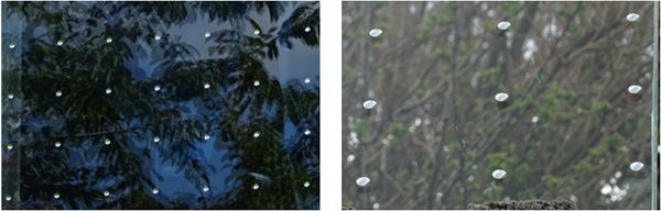
1. Birds mistake the reflections on the glass of the vegetation or surroundings as real (reflection misperception)
2. Birds fail to recognize transparent glass at all (transmission misperception)
The two scenarios are depicted in Figure 1. Although for humans inside buildings the perception of glass in transmission is dominant, reflected images are more common for birds.
Many cities and countries worldwide are putting regulations in place that mandate new buildings to include bird-friendly glass. As transparency in façades is still very much valued in connection with human wellbeing, reduced lightning requirements and as aesthetic element several technical developments have taken place to incorporate bird-deterrent elements into glazing solutions. Techniques that have been used are based on e.g. etched glass, fritted glass, glass with coated UV-markers, and most recently interlayers.
To understand trade-offs in glass design with bird-friendly glazing better, it is important to understand how the effectiveness of bird deterrent glazing solutions are tested and rated. In both Europe and the US, the effectiveness of glazing solutions is tested using (flight) tunnel testing. Bird tunnel testing for glazing products is a non-injurious, standardized binomial choice technique that uses wild songbirds to determine the relative effectiveness of patterns at deterring bird collisions. Previously captured, wild migrating songbirds are released in a flight tunnel and have the option to ‘exit’ by flying either towards a test glazing or unmarked control glass, seen at the far end of a dark, enclosed space.
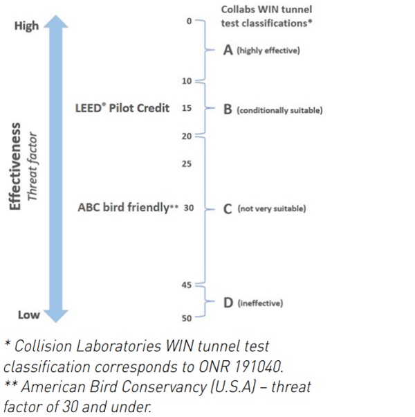
Both the test sample and unmarked control glass are protected by nets, so that no birds are injured in the determination of the effectiveness. The effectiveness is defined by the number of birds that fly towards the test glazing, divided by the total number of bird releases. Of course, the latter should be sufficiently large to derive meaningful results. More details are provided in one of the subsequent sections. In Europe, recommendations are based on the Collabs/ Biological Station Hohenau-Ringelsdorf classification scheme (equivalent to the ONR 191040 classification scheme for nonreflective, see-through situations), which designates only those markings as highly effective (“category A” in Figure 2) that achieve an overall result of no more than 10 % of directional flights towards the test pane [1].
In the US, the American Bird Society calls the effectiveness the “threat factor” and defines bird friendly glazing as having a threat factor of 30 or less [2]. Solutions with a threat factor of 15 or lower may be eligible for a LEED® pilot credit in this green building rating program. An overview of the effectiveness of bird deterrence glazing and the different classification is provided in Figure 2.
A common design strategy in bird friendly glazing is the application of patterns (e.g. stripes, dots) in or on the glass that are visible to birds in transmission, disrupting appearance of e.g. clear skies or vegetation that may be visible behind in the glass. In reflection, this may be less obvious as the reflectivity of glass depends on the viewing angle, the nature of the glass and other glazing elements, such as glass coatings, which can by highly reflective in nature. It should be noted that at wide angles, which provides the highest reflection, the risk of collision is smaller than at nearorthogonal flight approaches. The coverage area of the pattern applied is a key variable in a bird deterrent solution.
There are potentially many other variables beyond the coverage percentage alone that would determine the effectiveness as a bird deterrent solution, such as the pattern itself, the position of the pattern in/on the glazing, the transparency, the color or contrast, and reflectivity of the pattern. All these elements provide for a continued need for product testing. However, since the primary function of glazing is to provide daylight for human building occupants, and to provide lines of sight in and out of a building, patterns that cover a large area of the glass surface are generally not desirable. This identifies area coverage and effectiveness as typical major design trade-offs in bird friendly glazing design.
Another limitation in bird friendly glazing design is the huge variety in glazing configurations that can be manufactured and are used, relative to the number of tunnel tests that can be executed in a reasonable amount of time. There are only a few recognized test facilities worldwide at the time of writing. Testing is limited to the specific migration season of the songbirds and many bird releases are needed to establish effectiveness in a meaningful way. This means that only a fraction of actual configurations installed can be tested in that exact same configuration, even barring size and framing effects.
Therefore, in many cases, one is limited to e.g. a coating or frit print from a supplier, applied on a specific glass from that supplier, potentially in combination with functional coatings from the same supplier needed for the full performance for the glazing. So rather than an “add-on choice”, the bird-friendly glass design becomes a package choice where the thermal and solar performance requirements of the building, the daylight and viewing needs of building occupants, the architectural design intent and the effectiveness for birds all need to be combined. This can be quite challenging if all of the individual glazing element choices are limited by tested configurations for effectiveness in terms of bird deterrence.
A potential solution would be to assess configurations based on specific characteristics, such as visible light transmission and visible light reflectance, that are in between tested configurations with the same pattern. Such an approach is helped by the fact that most birds (tetrachromatic vision) have wider spectral sensitivity than humans (trichromatic vision). Mapping of configurations by their optical characteristics also enables dialogue with the ornithologists executing the tunnel testing. Many terms and elements that are well defined and meaningful for individuals working in the glass industry, such as clear glass, laminated glass, low-e coating and solar control coating, have little meaning to those working outside the industry. In turn, of course, most people focused on glass and glass products will have limited understanding of bird vision and the intricacies of tunnel and other forms of bird testing.
This contribution will provide a high-level mapping of current approaches to bird-friendly glazing in terms of effectiveness and coverage area. Furthermore, it will be demonstrated how for a specific bird-deterrent solution, mapping of glazing properties has allowed extending tunnel test results and ratings to a range of glass components, enabling conventional glass design to be combined with bird protection.
Mapping of current solutions
To be able to position various bird-deterrent glazing solutions, various technologies were mapped with regards to percentage covered area and percentage approaches. As the offer in this market segment has been rapidly growing in recent years, this can only be a snapshot in time, and the data should not be construed as comprehensive or current at the time of publication. To execute this work, third party data as published were taken into account, assuming these were collected in good faith, without an option of independent verification of their reliability. Test data from both the US and Europe were taken into consideration, despite differences in methodology. The results are provided in Figure 3.
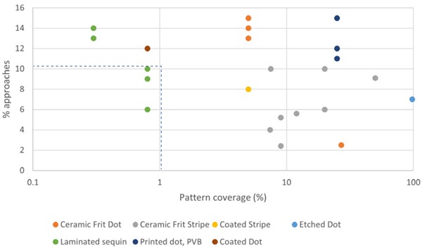
In the interpretation of Figure 3, it is important to realize that a low % of approaches (threat factor), is desirable, as is - generically speaking - a low coverage area. These solutions are grouped in the lower half of the graph. The area marked with the blue dotted lines is the area where a highly effective rating is obtained in combination with a coverage percentage of less than 1 %. All approach levels are lower than the minimum threshold set by the American Bird Society as “bird friendly” (threat factor 30) [2] or the threshold set in New York City Local Law 15, 2020 (threat factor 25). Most would even qualify for the threshold for a LEED Pilot Credit in this green building rating program.
However, quite a few solutions fail to reach a highly effective rating in the European methodology [1] now mandated in local regulations in e.g. Germany. There is a very limited number of solutions that are rated as highly effective and have coverage areas below 5 %, and only laminated sequin solutions achieve a high effective rating at less than 1 % coverage area. It should be noted that for fritted solutions, strengthening of the glass is a concurrent effect which affects not only the mechanical properties and breakage pattern, but also the options for post-production processing (needs to be cut to size prior) and visual appearance (e.g. roller wave/anisotropy). For the case study in this publication, a specific laminated pattern (“laminated sequins”) was reviewed.
Tunnel testing
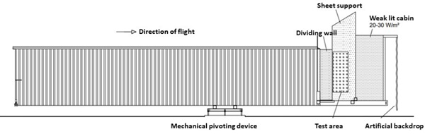
The description of the tunnel testing has been adopted from reference [3]. A tunnel test experiment examines the directional decisions of birds flying towards a marked and unmarked pane through a 7.5 m long flight tunnel, which is mechanically pivoted and can be manually positioned to follow the position of the sun. Thus, symmetrical light incidence on the test panes is ensured at all times, see Figure 4. The left and right half of the end of the tunnel are occupied by two different panes: an unmarked float glass reference pane on the one side and the test pane on the other, as in Figure 5.
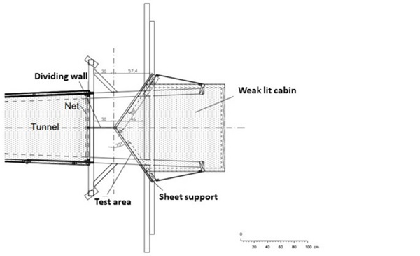
The birds used in the tests are wild birds from the ringing program of the Biological Station Hohenau – Ringelsdorf, Austria and therefore individually identifiable. This ensures that no bird is used for a test flight more than once per calendar day. The daylight-adapted test birds are placed in a start tube through the tunnel wall at the rear end of the tunnel, and immediately fly from the dark towards the open front end. A mist net commonly used to catch birds for ringing is placed 40 cm in front of the test panes.
The net's thread thickness of 0.1 mm falls below the birds' frontal visual acuity and is therefore not perceived. The birds are gently caught and protected from impact with the test panes and are immediately released after flight. The test flights are recorded from behind with a video camera. A ceiling, side walls and a partially translucent curtain create a weak-lit cabin behind the test panes. The trapezoidal sheet support prevents birds from seeing the sky and vegetation other than as reflections in the test area. The artificial backdrop consists of a white canvas in front of a camouflage net. To create realistic reflections, a darkened chamber measuring approx. 170 x 170 x 170 cm is mounted behind the test area, creating lighting conditions that correspond to the interior of buildings.
These lighting conditions are controlled with measuring instruments. Test pane and reference pane are mounted at an angle of 125° to the flight path of the birds. Similar to the side mirrors of a car, the panes create reflective images of the surrounding habitat in the birds’ visual axis as they fly through the tunnel. Since the tunnel is pivoted to follow the movement of the sun, the test and reference panes are always frontally lit. Depending on the light conditions (sun, clouds, overcast sky), more or less contrasting reflections of the surroundings occur on the panes, and structures of the chamber construction behind the panes become more or less visible, accordingly.
The surrounding vegetation is homogeneous, ensuring that reflections in both panes are as similar as possible. The birds' flight axis is parallel to the incidence of sunlight, with the sun always coming from behind. The panes do not receive any direct sunlight. After every three individual tests, the installed test panes are changed. The sequence of different test candidates and the positions of the respective test and reference panes are randomized. The flights and choice behavior in the individual tests are recorded by video camera, broken down into flight sequences, and controlled and evaluated in slow motion.
A case study for more flexible glass design
Base product description
The laminated sequin bird deterrent solution studied here is Saflex® FlySafe™ 3D. Saflex® FlySafe™ 3D PVB is a 0.76 mm interlayer with applied 3D-sequins. The sequins are visible for birds and humans and have a different color front to back. The sequins are reflective silver on the front, as viewed from the exterior, and black on the back (interior) so as not to obscure views or diminish visual quality from the inside. The sequins consist of 9 mm diameter round markers, arranged in a grid with a distance of 90 mm from sequin center to center. This grid corresponds to an overall coverage area of 0.8%.
For use in a laminate, a covering layer of clear 0.76 mm or thicker Saflex® PVB interlayer must be placed on the silver side of the sequins in contact with the glass. A typical laminate configuration can be seen in Figure 6. The picture in Figure 6 demonstrates to some extent that the reflective sequins do not have a uniform mirror-like appearance, but rather a seemingly three-dimensional surface structure, which results in subtle twinkles depending on the angle of approach.
Evaluated systems
Three glass configurations were evaluated in under the flight tunnel test protocol described previously:
- 44.4 laminate using conventional clear glass and a Saflex® FlySafe™ 3D interlayer in combination with Saflex® Clear 0.76 mm cover layer in front of the sequins (Configuration 1; 44.4 Saflex® FlySafe™ 3D)
- 44.4|16|4 insulated glazing unit: front pane laminated coated glass laminate using conventional clear glass and a Saflex® FlySafe™ 3D interlayer in combination with Saflex® Clear 0.76 mm cover layer in front of the sequins with a robust, low-e coating in position #4, a 16 mm air space, and a mm clear glass back pane (Configuration 2, 44.4 Saflex® FlySafe™ 3D_c#4|16|4)
- 46.6c#4 coated glass laminate using conventional clear glass and a Saflex® FlySafe™ 3D interlayer in combination with Saflex® Clear 0.76 mm cover layer in front of the sequins with a robust, neutral solar control coating in position #4 (Configuration 3; 46.4 Saflex® FlySafe™ 3D_c#4)
The solar and visible characteristics of these two configurations are listed in Table 1 beside.
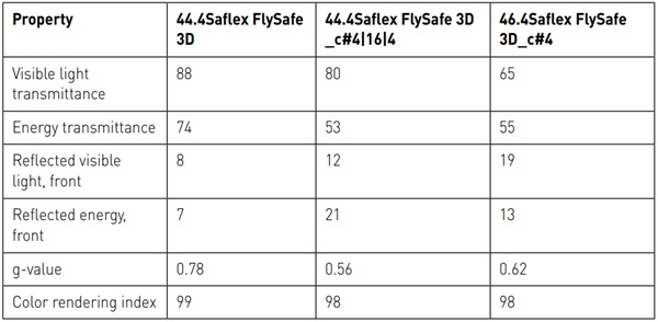
It was verified that the differences in the values are caused by the presence of the coating as the difference in glass thickness is too small to have a material effect. The coated systems have a higher reflectance, resulting in a step wise increase of reflected light (8, 12 and 19% respectively) as well as a stepwise decrease of overall visible light transmission (88, 80 and 65% respectively)
All three systems were tested in the flight tunnel test previously described and resulted in less than 10% of approaches (threat factor) and as a result were rated as highly effective [3, 5]. It does show that the unique Saflex® FlySafe™ 3D appearance and grid is effective in reducing bird approaches in the tunnel test, even with the more reflective, lower transmission coated systems. This is remarkable as the testing protocol was executed focused on effectiveness in reflection. To be able to apply the flight tunnel test to a wider array of glazing elements, a number of potential variations were mapped by modelling.
Clear glass
The visible light properties of 51 different float glasses of ten different float glass producers for thicknesses of 4, 6 and 10 mm with different iron content were evaluated. All products tested had a visible light transmission between 92 and 87% and a light reflection of 8 or 9%. Given the range of visible light properties of the three tested Saflex® FlySafe™ 3D configurations and the resulting “highly effective” rating, it was accepted that the source of the float glass was not a material factor in the outcome of the tunnel test. Clear glasses from different suppliers can be used for the assembly of Saflex® FlySafe™ 3D configurations without a need for re-testing, providing no other glazing elements are present that affect visible light properties in a material way.
Laminated glass
The visible light properties of 5 different laminates (xx.4 with x either 4, 5, 6, 8 or 10 mm glass) based on conventional clear float glasses were evaluated. All products tested had a visible light transmission between 88 and 84% and a light reflection of 8%. Given the range of visible light properties of the three tested Saflex® FlySafe™ 3D configurations and the resulting “highly effective” rating, it was accepted that the thickness of the laminate was not a material factor in the outcome of the tunnel test within the evaluated boundaries.
Low-e coated glass in IGU’s
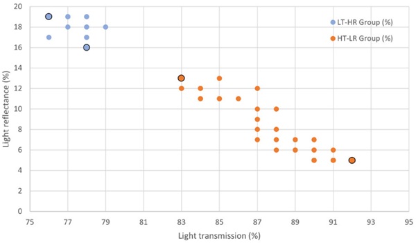
As an approach to model and review performance insulated glazing units (IGU’s), it was first mapped how the properties of basic low-e glasses vary by light transmission and light reflection. In order to cover a wide range, data for 180 low-e coated glasses from ten different suppliers were compiled. Besides supplier, glass type (low/mid-iron), glass thickness (4, 6, and 8 mm) and coating type (typically 2-3 types per supplier, but up to 8 types) were other variables. As glass thickness turned out not to be a key variable, the results are shown in Figure 7 for 4 mm glass.
It should be noted that Figure 7 contains many overlapping datapoints, as both properties are provided with rounded numbers. Two groups of coating are readily identified: a group with higher reflectance (> 15% and lower transmissions (LT-HR group, blue dots)); and a group with lower reflectance and higher transmissions (HT-LR group, orange dots). In order to assess the effect in realistic configurations, the most extreme coated glasses in each group, marked with black bordered dots in Figure 7, were taken as a basis for IGU modelling. In this way, it can be assured that the full range of low-e coated options is covered in the IGU modelling, without having to model each potential variation in IGU composition.
As an example of the approach, for all four marked coatings in Figure 7, four different types of IGU’s were modelled:
- A single laminated IGU with a low-e coating in position #5
- A double laminated IGU with a low-e coating in position #5
- A single laminated triple IGU with two low-e coatings in positions #4 and #7
- A double laminated triple IGU with two low-e coatings in positions #4 and #7
The results are shown in Tables 2a and 2b.
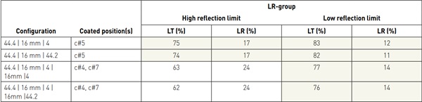
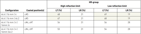
Table values with a green background are within the limits of tested configurations that could be rated as highly effective, respectively 65% for light transmission and 19% for light reflection. In the HT-LR group (Table 2a), all double IGU’s fall within the tested range. Even for the double coated triple IGU, the lower reflection limit coating is well within the tested range of properties, with potential to review higher reflectance coatings. At the very limit of this group in terms of reflection, the transmission and reflections are still outside the tested range. In the LT-HR group (Table 2b), even if assembled in a single laminated IGU, the reflectance values increase over non-assembled coated glass, causing the higher reflection limit coating to fall outside the tested range. Only the low-e coating with the lowest reflectivity in the HR group falls borderline within the range of tested configurations. For the double coated triple IGU’s, all configurations are outside the tested range for both transmission and reflection.
Mapping of solar control coated IGU’s The broad approach as used for the low-e coatings is not readily applied to solar color coatings, as there is a wide array of coating technologies, performance characteristics and visible properties to choose from. By design, many have lower light transmission and colored options (e.g. grey, blue, green, etc.) are also common. Often, there is a highly reflective or relatively low reflection (“neutral”) variant to choose from. For purposes of this work, the current offer of neutral high transmission solar control options in Europe was mapped by light transmission and reflection (to the outside).
No less than 24 options from 8 producers were identified in 6mm glass, as mapped in Figure 8. Most of the datapoints in the upper left corner are more robust solar control coatings that can be used without edge deletion, in combination with a limited selectivity (visible light transmission over g-value). The marked datapoint (large dot, black border) in the center of points on the right side of the map was used for further modelling, to review if such a coating would still supply values that are within the range of glazings tested in the flight tunnel tests. Double and triple laminated glazing units were considered, in either the absence or presence of low e-coating in the back pane. The results are shown in Table 3.

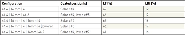
Table values with a green background are within the limits of tested configurations that could be rated as highly effective, respectively 65% for light transmission and 19% for light reflection. The other configurations are close, and by specific choices for either the low-e coating, or the glass type, or the specific solar control coating chosen a configuration could be selected to have the overall required glazing properties (U-value, g-value, light transmittance), while still staying with the tested boundaries for the laminated sequin bird-deterrent solution. As an illustration, the use of low-iron glass rather than conventional float glass in the triple IGU increases the light transmission a few percent, moving it inside the tested range.
The wide array of solar control coatings available does drive the question what property would be of most concern. At the limit of light transmission, birds are likely to avoid solid appearing objects [6]. In that sense, the darker a glazing gets in transmission, the less prone it is to bird strikes. In addition, the contrast with the high reflective sequins only increases, potentially making lower light transmissions acceptable without further testing. In contrast, the more reflective the coating used is, the lower the contrast with the sequins becomes. Here future testing will still be invaluable to demonstrate any reduction of effectiveness with regards to bird strikes for the laminated sequin solution. Use of color in glazing, be it derived from mass colored glass, coatings, or interlayers typically reduces the light transmission of the glazing, and in that sense has an impact independent of the color tone. Color layers in front of the laminated sequins should be avoided without testing, as they reduce the reflected contrast with the laminated sequins.
Conclusions
Sophisticated test protocols are available to assess the effectiveness of glazing configurations with regards to their potential to avoid bird collisions. However, given the wide array of glazing options, some degree of interpolation is needed to match the glazing performance from a building: physical aspects, design aspect, occupant needs for daylight and view, and bird-deterrence. Based on a technical market mapping, it could be shown that a laminated sequin solution is one of the most advanced solutions available in terms of both coverage area and effectiveness. With some constraints, this solution can also be used in a wide array of glazing configurations with properties within the tested range for this bird-deterrent solution, including use in insulated glazed units, either in the absence or presence of low-e or solar control coatings. It is important to verify the characteristics of the final project configuration relative to tested configurations to assess if the effectiveness rating can be maintained without further testing.
References
1) Rössler, M.; Doppler, W. Vogelanprall an Glasflächen, brochure Wiener Umweltanwaltschaft, 2019.
2) Sheppard, C.D. Evaluating the relative effectiveness of patters on glass as deterrent of bird collisions on glass in: Global Ecology and Conservation, e2019, (https://doi.org/10.1016/j.gecco.2019.e00795).
3) Rössler, M. Reduction of Bird-Window Strikes – evaluation of SEEN glass elements, 2020.
4) Eastman Chemical Company Product Technical Sheet Saflex® FlySafe™ 3D available from https://www.saflex.com/technical-documents, 2022.
5) Rössler, M. Vogelanprall an Glasflächen – Untersuchungen von Saflex® FlySafe™ 3D / SEEN shiny 9/90mm und Saflex® FlySafe™ 3D / SEEN matt 9/90mm, 2022.
6) Schmid, H.; Doppler, W.; Heynen, D.; Rössler, M. Vogelfreundliches Bauen mit Glas und Licht, ISBN 978-3-9523864-0-8, Schweizerische Vogelwarte Sempach, 2012.