

This paper was first presented at GPD 2017 by Yu Hui, Nicolas Leduc, Tan Hui, Florian Rochereau and Jin Shihui.
Abstract
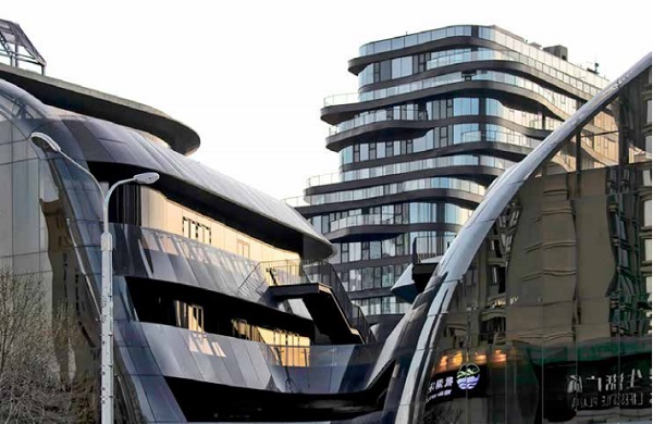
In this paper, we present the workflow of design and construction of Chaoyang Park Plaza tower façade located in Beijing, China, which is one of the most challenging façade system due to its complex double curved geometry from architectural scheme by MAD Architects.
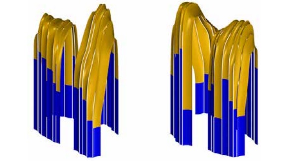
The system is divided into two main zones one with purely cylindrical façade and the others with twisted roofs strips which blend smoothly into the tower faces.
The initial surface was rationalized with a cylindrical fitting algorithm. The goal is to find a panelized surface which keeps a very smooth appearance, while at the same time minimize cold bending amount. This optimization process also had to consider the unitized façade frames to obtain a buildable geometry with straight extrusion mullions and planar circles transoms, following to the parameters extracted from the reference surface. (Twisting angle to mullion, dihedral angles, etc.) The waterproofing design for sloped parts was specially investigated.
The design integrated a fully automated manufacturing process which included 7600 glass panels produced according to the limitation of size of the bending machine. A 3d BIM and an automated digital manufacturing technology were used to cut the frames with variable angles, which made possible to realize the 3-dimentional geometry of each component. These components were then assembled with a small amount of cold bending applied in factory.
Introduction: Challenge and Strategy
Free-form façade has become more common in China. A series of technical improvements support this trend with new tools and methodology enabling to realized what has become commonly referred as complex geometry.
In this paper, we are sharing the experience of designing and fabricating of Chaoyang park plaza tower, which is the most complex freeform high rise facade in china. RFR shanghai was contracted by the developer and has done the geometry optimization, the façade system design work which has started in 2014 and followed by the supervision of the whole construction process until its completion in 2016.
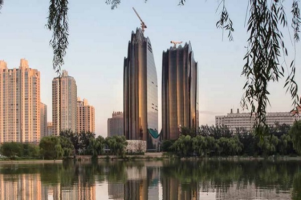
Chaoyang Park Plaza is in the central business district (CBD) of Beijing. A pair of asymmetrical towers up to 143m creates a dramatic skyline in front of the park. Vertical ridges and valleys define the shape of the exterior glass facade, as if the natural forces of erosion wore down the tower into a few thin lines, according to the architectural concept of MAD architects, the “Shanshui”. The challenge is thus to translate this artistic intent into a design and fabrication process and to apply to it an actual tower with an industrial mass production process, cost-effective and with off the shelf fabrication technology.
The Challenges of Chaoyang project can be summarized as three aspects:
- Double curved geometry for the Glass;
- Double curved geometry for the façade system;
- Industry 3D design and production capacity
First, the double curved geometry pushed the limit of the current façade industry, especially for high-rise building. 54% of curved surface are highly doubled curved (radius <12m). The necessary geometry rationalization had not only to keep the smoothness of the surface desired by MAD, but also keep the glass panels within the constrain of standard production capacity and with the maximum curved glass sizes which could be produced at the time. After reviewing possible solutions for glass panels such as hot forming double curve glass, quadrangular flat panels, twisted panels (flat panel cold bended), we concluded that we should focus on a well-known approach but never applied at such scale: A cylindrical best fit optimization.
Learning from the experience of the foundation Louis Vuitton in Paris [1], the Eiffel tower pavilion [2] for the principle of cylinder fitting, and from Strasbourg TGV Station [3][4], Lille TVG station much earlier and Avignon TGV station for cold bending with single curvature, we decided to pursue the work and applied these principles to the Chaoyang project.
In this case, the joint layout of the reference surface is horizontally rebuilt as planar arc, and vertically polygonized. The rebuilt semidiscretized surfaces are curved smoothly in the horizontal direction and leave minimal kinks at the adjacent floors, forming general cones at each floor, which gives the best results for local cylinder fitting. The deviation stays within maximum 30mm between the rebuilt surface panel and the fitted cylinder panel. This deviation is even more reduced by applying a cold bending onto the glass to the frame.
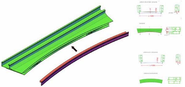
Second, the double curved geometry is also a challenge to the facade system design. To obtain a curved unitized façade with smaller deviation at the corners of each components, a common and cheap solution is to fabricate planar components and apply cold bending on site. But for Chaoyang project, the curvatures are big and geometry is freeform without repetition, a three-dimension frame system is therefore preferred. The frames are CNC cut with individual angles and assembled non-planar in the factory. It is not realistic to have all aluminum extrusion profiles curved and twisted, our solution aims to have straight extrusion mullions following average surface normal direction at each floor. In this way, straight and CNC profiles would provide the buildibility and precision required by the system.
Moreover, the complexity of glass panels and frame components is demanding for the contractor’s not only 3d design and fabrication capacity but also a very tight assembly precision. Today’s automatic curving machine can produce perfect quality tempered glass with no repetition radius and edges. Computer Numeric Controlled machines are used to cut the frames with difference angles and carved the transoms in arc, which made possible to obtain the complex 3-dimentional geometry for each component. The contractor pursued the fabrication work with its own capacity and expertise under collaboration and supervision of RFR Shanghai.
Geometry optimization
Reference geometry
Reference surface and typologies
At the very beginning of the project are the “reference surfaces”.
In the preliminary stages of design, the whole facade complex is modelized by simple surface patches with no thickness, so called “reference surfaces”. It expresses the architectural design intent and thus represent a guideline shared by MAD architects and the engineering consultants working on the project. The reference surfaces are frequently updated as the project evolves over time.
The reference surfaces fulfil another important purpose: they guaranty the consistency of the geometrical design of all the facade components. Each part of the facade has a well-defined relationship with the surface, in terms of offset, orientation, etc.
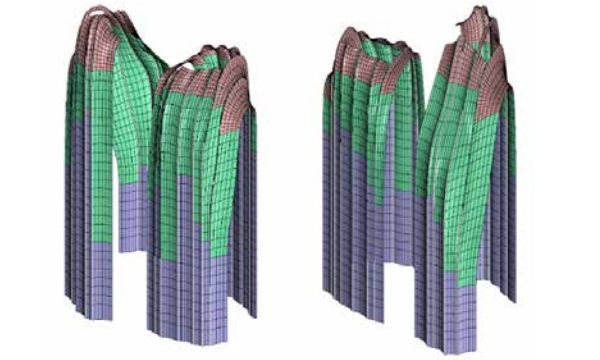
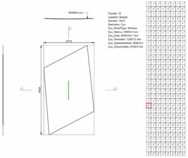
The 21.300 m² of reference surfaces of the Chaoyang Park Tower can be described in terms of geometry or facade technology. See in Figure 2 and Figure 3.
Reference jointing layout
The reference jointing layout is complementary to the reference surfaces for a precise definition of the facade components. It consists in a bidirectional network of curves located on the reference surface and represents the design intent for facade subdivision into panels. As shown in Figure 4.
Note that the intersection of these planes and the reference surface generates arbitrary planar curves.
Surface geometry: rationalization strategies
Facing the problem of construction of complex geometry, several strategies could be envisaged. Their relevance depends on many criteria such as the respect of the design intent, the cost or the technical performance. With no claim to be a rigorous classification, we propose three possible strategies: no rationalization, pre-rationalization and post rationalization.
No rationalization
This first option consists in building the surface “as it is”, which often implies to build unique panels in their cutting patterns as well as their 3d shapes. The balustrades of A4-A7 buildings can be considered partly in this class. Changing partition direction can reduce the curvature of the panel, but it’s not preferred by architect, part of the balustrades are still made of doubly-curved glass panels.
Pre-rationalization
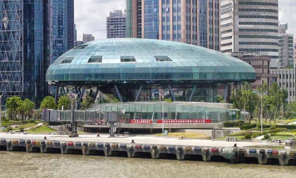
The pre-rationalization approach limits the design space to families of surfaces whose geometric properties provide technological benefits. Spheres, cylinders, cones and torus are obviously part of theses surfaces. The 80’s and 90’s saw an extensive use of revolution, translational and homothetic surfaces that allowed more freedom than basic geometric primitives (See Figure 6 Shanghai ocean terminal).
It should be notice that this kind of geometry is at the heart of contemporary research again. Mesnil et al propose intuitive tools that guaranties the planarity of quadrangular meshes from architectural sketches [5]. Another article widens the range of prerationalized surfaces with the ones of Monge while guarantying planarity of quadrangular faces and torsion free structural nodes at the same time [6].
Post-rationalization
Post-rationalization is a most recent approach whose development has been enabled thanks to the extensive computing power and further progress in discrete differential geometry knowledge.
Based on optimization process, the discrete panel solution tries to best fit the reference surface of the architect. One must distinguish between two distinct kinds of approximation: local and global optimization.
For local approximation (easier implementation and less computing-time consuming), each individual panel tries to fit as well as possible the reference surface. Since there is no adjacency relationship between two consecutive panels, this approach may lead to a heterogeneous distribution of the performance.
On the contrary, a global optimization approach tries to minimize the divergences by relaxing the panel solution at a global scale under a set of control constraints (planarity, position and tangency continuity between panels, and closeness to the reference surface…). The optimization is no more driven by the best individual approximation of a common reference (the reference surface) but the best collective performance of a panel population. A global optimization approach is likely to homogenize the distribution of the performance and provide overall improvements.
Chosen approach
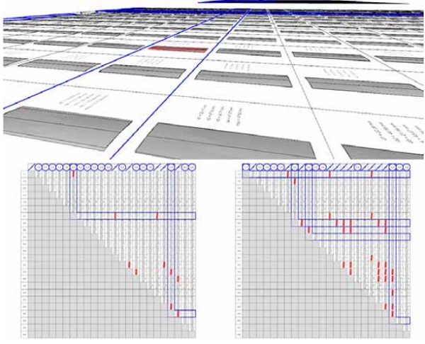
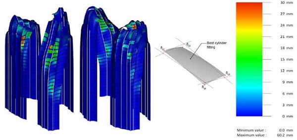
Let us explain why the selected approach for the facades of the Chaoyang Park towers has been oriented to a post-rationalized approach. Building the design surfaces as-is was deemed impossible due to economic feasibility reasons. The huge quantity of panels (more than 7000) could let us think that repeatability would make possible the use of a unique mold for several glass panels. Unfortunately, despite in depth studies, the numerous geometric degrees of freedom (in plane cutting pattern et 3d shape) did not allow an effective panel clustering under an acceptable tolerance. Figure 7 shows the study of panel’s possibility of repetitive fabrication.
On the other hand, the complexity of the design surfaces could not be captured using surface primitives proposed by the pre-rationalization approach.
Thus, the architectural requirement about the respect of the design intent led us to adopt the post-rationalization approach. The state of the art of optimization tool, with further adhoc developments allowed us to approximate the design surface with a good fidelity while providing excellent technical properties to the panels and the support structure.
Panel geometry: rationalization strategies
Once a rationalization option for the reference surface has been chosen at the global scale, another question rises at the panel scale. As we saw previously that unique doubly curved panels were not an economic option, a survey in the field of industrial fabrication of glass panels gives some clues. We examined three options: flat, twisted and cylindrical panels. From a geometrical point of view, the approximation quality (and complexity) of the reference surface is increasing from solution 1 to 3.
Geometrical features and technical consequences for glass panels
A target panel is defined as a reference surface patch bounded by four curves of the reference jointing layout. The goal of the geometrical approximation being to minimize the distance between the target panel and the manufactured panel, we have to choose the most appropriate surface geometry.
Quadrangular flat panels are of course the first option which comes in mind since it is a proven and reliable technology and from far the cheapest way to produce and assemble insulated glass panels. But the facetted aspect (discontinuity in tangency) was rather inappropriate when the reading of the curvature was a priority for MAD architects. Moreover, one should notice that on a given doubly-curved surface, four arbitrary point are not coplanar.
Therefore, gaps between two consecutive panels (discontinuity in position) give a scale-like aspect to the facade, raising once more the question of architectural aspect. Furthermore, on a technical point of view, divergences between adjacent panels is a critical condition for the water-tightness of the facade which should be carried out by a nonstandard technical detail.
In order to take advantage of the hardiness of planar panels manufacturing while minimizing the waterproofing issues mentioned above, an option with twisted glass panels has been envisaged. This method forces the glazing unit within its elastic domain to a target position defined by the reference surface. Special attention will be given in the specific case of double glazing. As a matter of fact, in addition to mechanical stress in the glass due to twisting, the shear strength in the sealing joint may damage the isolating performance of the panel. The twisting of the panel only improves slightly the facetted aspect of the facade.
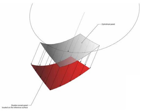
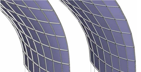
Increasing the geometrical degrees of freedom of the panel, and then its manufacturing complexity, let us approximate the target panel with lower tolerance. Such is the case with rotational cylinders which present a unique curvature radius for each panel. However, this unique radius can be different for each panel. The generatrices of the cylinder are parallel to each other but have an arbitrary direction regarding the edge of the panel. For this reason, this type of cylinder is called “arbitrary cylinder”.
This option greatly enhances the visual aspect of the facade in that it respects the notion of curvature proper to the facade design. From a technological point of view, the divergences in position and tangency between two consecutive panels being minimized, the water-tightness technical details can be addressed in a more traditional way.
The use of rotational cylinders can be justified by an industrial reason. Today’s bending machines enable the fabrication of cylindrical panels with variable radii without the use of individual mold for each panel. And these systems provide excellent quality tempered bent glass. Unfortunately, shapes like general cylinders or cones, which would increase the approximation performance are not available yet.
An arbitrary intersection of a cylinder and a plane is an ellipse portion. However, it exists two given planes along which the ellipse portion becomes an arc of circle and a straight line. Thus, a specific orientation of the cylinder enables to get peculiar geometric properties for the edges of the panel. For this reason, this type of cylinder is called “oriented cylinder”. One should notice this slightly affects the quality of the approximation: it is not necessarily the optimal cylinder regarding the reference surface since a constraint has been imposed on the orientation of the generatrices.
Implications for support structure
The choices for the geometry of the panels have been taken, measuring the consequences they imply on the structure that holds the glazing units: two mullions (vertical direction) and two transoms (horizontal direction) The manufacturing complexity of these structural components is highly related to the geometrical complexity of the profile axis (plane or spatial curvature) and the geometrical behavior of the cross-section (torsion). The various options are summarized in the following table.
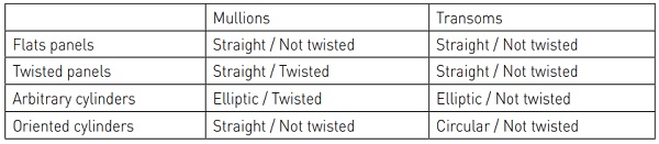
Chosen approach
The chosen option is the oriented cylinder. It seems to represent the best possible accommodation between the architectural aspect and the technical performances of the facade panels and its support structure.
Design process
Reference surface remodeling
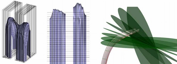
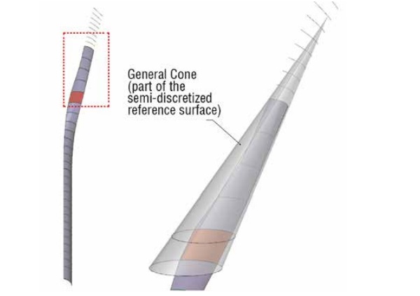
In order to take advantage of the geometrical and technical properties of the panels (rotational cylinders) and the structural elements (straightness of mullions and circularity of transoms), the remodeling of the reference surfaces allows a better approximation. With reference to the rationalization strategies proposed earlier, we set up a hybrid approach (pre & postrationalization) by applying panel optimization to new reference surfaces modeled between two floor levels.
Each edge of slab, initially defined as an arbitrary planar curve is rebuilt by an arc of circle. Through two arbitrary circles whose support planes are parallel, it is possible to generate a general cone. This set of surfaces is a semi-discretized representation of the reference surface. The newly constructed surface is smooth in the horizontal direction and polygonized in the vertical direction.
Cylinder approximation
The subdivision of the general cones by the reference jointing layout defines target panels to be approximated. A cylindrical local approximation is then performed for each panel.
Since the radii of curvature of two consecutive slab edge are quite similar, the cylinder approximation is of excellent quality. The minor divergences between the approximate cylinder and the semi-discrete reference surface are cancelled by cold-bending the panel.
Unrolling
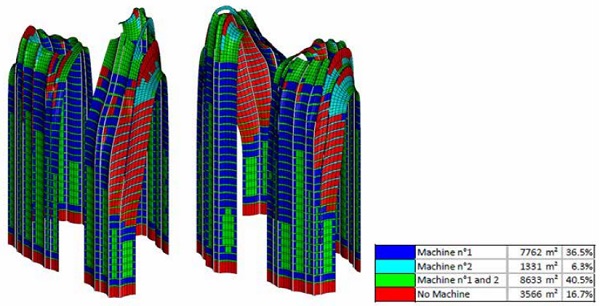
The selected geometrical option is entirely based on automatic glass bending machines which are able to put the glass panel in shape and temper it without the use of molds. However, the bending bed size limitations and the large format of the panels of the towers required in-depth studies of the compatibility between unrolled cutting pattern and the available machines on the market.
This work led to an iterative process with the architect to densify the jointing layout where needed. For the vertical and slopped part, the target panel is systematically horizontally subdivided in two parts: window and spandrel. For the roof part, no horizontal subdivision is performed.
Additional vertical subdivisions are locally introduced where the panel is too large to fit maximal dimensions of the bending bed. At the end of the subdivision process, 7257 panels have been automatically unrolled in a format close shop-drawings, including graphical information (cutting pattern, orientation of the panel along bending axis of the machine, bounding box, …) as well as textual information (location, panel naming, radius of curvature, …)
Analysis: cartography and bill of quantities
These geometrical studies were supported by a quantitative analysis of the various geometrical parameters with help of cartography and statistic recurrence (extreme and median values, distribution of the population by class). This was very helpful to feed the other related studies and particularly the technical detail design.
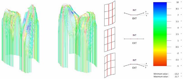
As an example, we can mention the dihedral angle between two panels. The data extraction of this geometrical parameter is directly linked to the range of variation the mullion or transom is likely to absorb. This quantitative approach has also proved its usefulness for reliable and fine pricing by sorting components and systems by class of complexity.
Façade System Design
Frame orientation
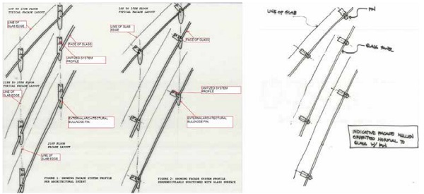
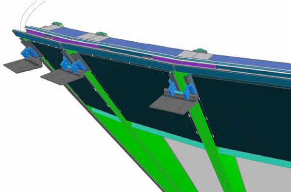
From the geometry optimization process, semi-discretized surfaces are generated with general cones and ruled surfaces whose generatrices are mainly vertically oriented. Mullions front axis, equivalent to the glass division lines, are the result of the intersection of these reference surfaces and vertical planes. 98% of these axes are within 5mm deviation from straight lines, so that mullions can be simplified to straight extrusions. As mentioned above, horizontal divisions are horizontal planar arcs which can be considered as planar circular extrusion transom. Both of these profiles are suitable for industrial mass production.
The solutions of straight, non-twisted extrusion and mullion orientation with normal of surface result in the mullion orientation solution shown in Figure 15 image on the right. Straight mullions are segmented and take average normal direction of surface of each floor, thus upper and lower floor mullions are oriented separately with continuous rotation center at mullion front axis.
On the left, the non-rationalized approach leads to smooth but double curved and twisting mullions not feasible for industrial production. Because of the normal difference which appears from one floor to another within one mullion strip, a clustering process has been studied to verify that the deviation induced by this twist was in acceptable range and taken with structural silicon. In practice, results show few mm deviation for the back of the mullion between floor n and floor n+1, 95% were less than 5 degrees difference.
System detailing design
Once the principle of the façade system is defined, further studies have been made to optimized and achieve the required precision, and performance while fabrication cost is always considered in parallel.
Bending process for aluminum extrusions is not reliable in precision, so that we decide that main part of transoms are also kept straight but CNC cut in arc, only the small front part fixing the glass is bended and attached to the main part.
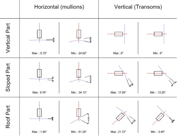
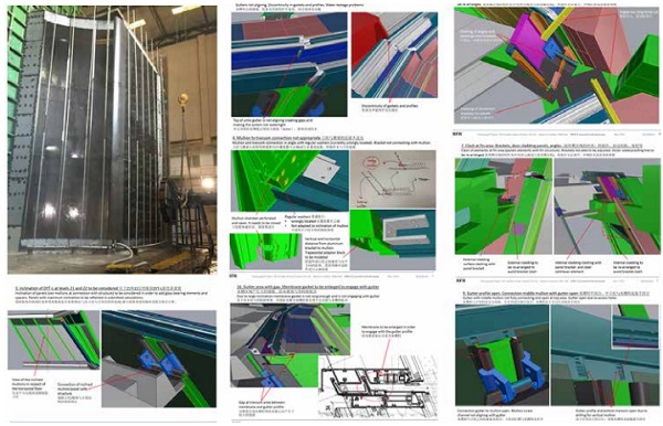
The solution of three-dimensional frame system provides buildability and precision, but there is an issue with inclined frames not meeting at the same point at joints. Figure 17 shows the variety of dihedral angles between adjacent transoms and between upper lower mullions.
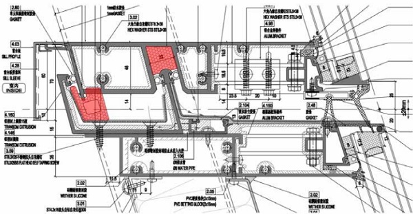
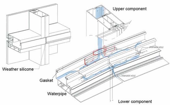
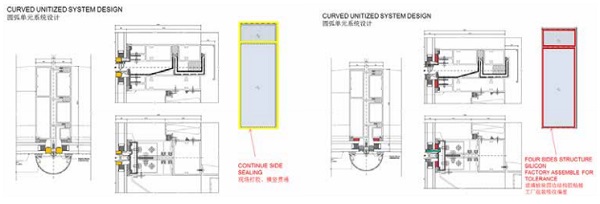
Because of mullions inclination changing from one floor to another and the constant depth of the profiles, the resulted intersections with the transom plane have different length. An adaptable gutter integrated within the transom profiles has been designed to slide and match with the inner cavity of the mullion for waterproofing continuity.
A tolerance uptake was also introduced to reduce number of the dies. A clustering process has been applied to the frame geometry to minimize the number of die for mullions and transoms used on the overall project. Thanks to this process, with a step of 2.5 degree inclination of gutter between each die, only 2 dies were necessary for the mullions and 6 set of dies were necessary for the transoms.
Sleeve covers over the gap of transom gutter on site and is sealed with silicone. Rainwater occasionally coming into the inner cavity gathers in the transom gutter and flow through the holes into waterpipe then come outside. In addition to typical unitized façade’s drainage system, special treatment is used to secure waterproof performance. Because the slope angle of the façade with ground is very small at upper part of the tower, the façade is more working as a skylight. Structural silicon is used to fix glass panels and the frames while assembling in factory, and weather silicon was applied to the gaps of components after they are installed, leaving a few holes for air going through the balance pressure cavity and outside.
Realization
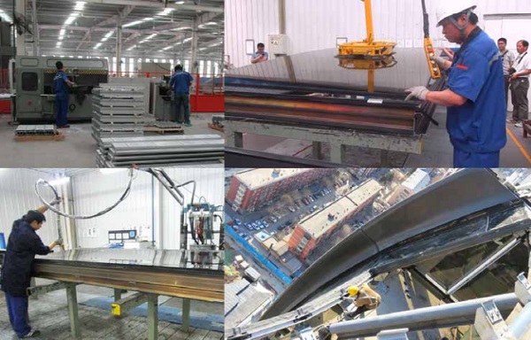
Façade contractor Jangho got involved in the project since Visual Mockup phase. Research and experiments were carried out, such as VMU, PMU, glass smoothness checking etc. With the help of 3d BIM, contractor defines more clear and detailed principles and parameters for fabrication and construction.
Parameters such as: inclination angle of the mullion in relative and absolute coordinate, adaptable gutter position relative to transom, cutting angle of transom with inclined mullion, orientation plane of mullion, torsion angle of mullions between upper and lower levels, etc. are invested carefully to specify each component in 3D. After construction drawings and BIM models are checked and confirmed, it come to fabrication phase. Shop drawings are directly extracted from Jangho’s customized Pro-E parametric system.
7600 pieces of glass panels are fabricated as the execution drawing mentioned above. Width of glass panel bounding box is set within 2.4 meters. Unrolled panel edge length and its difference with corresponding frame length are checked to make sure the glass can fit into the frame with enough margin for structure silicon. Arc height is increased a few millimeters so that when the glass panels are cold bended to the frame, the glass can attach more tightly to frame while cold bending.
The components are assembled with one corner lifted in space and three other points lay planar, cold bending is applied along long edges. Small amount of cold bending doesn’t deform the frame more than 5mm, so components are plugged together with little adjustments during on-site installation. Components are installed with bottom transoms plugged and fixed in position first and then top corners are pushed or pulled to the designed position, to erase the deformation caused by transportation and cold bending stress. Edges and joint sealing are applied at the same time.
Conclusion
Chaoyang Park Plaza Tower represent today one of the most complex double curved façade build today not only in China, but also in the World. As described above, the most advanced research on geometry and fabrication processes have been applied to the project to achieve this great result. Results that would not be possible to be achieved with a close cooperation between Architects, Façade and Structure Consultants and Contractors.
Acknowledgements
Façade consulting RFR Shanghai, with the team: PD: Yuhui, PM: Tanhui, team: 谭晖, Armin Kainz于辉, Nicola Leduc, 金长发, 赵燕 华, 王先锋,Florian Rochereau , 贺学峰, 朱申亚, Philippe Bompas, Nicolas LEDUC, currently at T/E/S/S, atelier d’ingénierie. PhD student at Laboratoire Navier. Geometry optimization of this project has been done when he was working at RFR sas Paris. The writing of this paper is funded by T/E/S/S and VIRY. Architect MAD; Façade contractor Jangho; 李剑星, 程宏波 from Jangho shared their experience of this project.
References
[1] RAYNAUD J VAUDEVILLE B. How irregular geometry and industrial process come together: A case study of the Foundation Louis Vuitton, Paris In Advances in Architectural Geometry 2012 Springer Vienna
[2] Schiftner, A., Leduc, N., Bompas, P., Baldassini, N., & Eigensatz, M. (2013). Architectural geometry from research to practice: the Eiffel tower pavilions. In Advances in Architectural Geometry 2012 (pp. 213-228). Springer Vienna.
[3] BLASSEL, J.F. AND PFADLER, A. 2008. La gare de Strasbourg. In Construction Métallique, n° 1, page 15-36.
[4] Blassel, J.F. 2007. New Glass and Old Stones. Glass Performance Days 2007.
[5] Mesnil R., Douthe C., Baverel O., Marionette Mesh From Descriptive Geometry to Fabrication-Aware Design, 5th Symposium on Advances in Architectural Geometry (AAG), 2016, p.62-81 ;
[6] Mesnil R., Douthe C., Baverel O., Isogonal moulding surfaces: a family of shapes for high node congruence in freeform structures, Automation in Construction (2015) Vol 59, p.38-47;


Comments
A cylindrical fitting approach was used to rationalize the starting surface. The objective is to design a panelized surface that minimizes the amount of cold bending while maintaining a highly smooth appearance.
One of the two primary zones of the system has a fully cylindrical façade, while the other two have twisting roof strips that integrate seamlessly into the tower faces.