Article Information
- Digital Object Identifier (DOI): 10.47982/cgc.8.388
- This article is part of the Challenging Glass Conference Proceedings, Volume 8, 2022, Belis, Bos & Louter (Eds.)
- Published by Challenging Glass, on behalf of the author(s), at Stichting OpenAccess Platforms
- This article is licensed under a Creative Commons Attribution 4.0 International License (CC BY 4.0)
- Copyright © 2022 with the author(s)
Authors:
- Gregor Schwind - Institute of Structural Mechanics and Design, Technische Universität Darmstadt
- Franz Paschke - Institute of Structural Mechanics and Design, Technische Universität Darmstadt
- Jens Schneider - Institute of Structural Mechanics and Design, Technische Universität Darmstadt

Abstract
In the structural design of facade glazing, various types of loads such as dead weight, wind and climatic loads (pressure differences) must be taken into account. In practice, however, there are many cases of damage that can be attributed to direct solar radiation. In these cases, a so-called thermally induced fracture takes place, which can occur as a result of large in-plane temperature differences within the glass. Due to the increasing complexity of glazing constructions, this load type should be taken into account in future glass design. For this reason, thermal-mechanical investigations, were conducted. Commercially used double and triple insulating glass units were considered as vertical glazing and the solar direct absorptance per glass pane was varied.
For numerical calculations, measured temperature data from the German Weather Service and free available Clear Sky model data were used as meteorological input. The results show that solar irradiance, along with temperature, is the driving influence on the thermally induced stress in insulating glass units. The investigations indicate that the inner pane becomes relevant on colder days and the outer pane on warmer days. Results also show, that the level of the outside temperature plays a negligible role for the thermally induced stresses of the middle pane.
1. Introduction
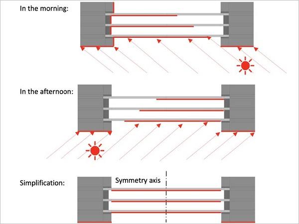
Facade glazing is exposed to different loads such as dead weight and wind loads and must be designedaccording to the relevant standards. In the case of insulating glazing, climatic loads such as the change in air pressure due to the difference in height (production site to installation site) or due to the expansion of the gas in the cavity between the panes due to a change in temperature are also taken into account. In connection with these climatic loads, however, the action on the glass due to solar irradiance is often neglected, which can be relevant for the dimensioning of glazing, as many cases of damage from practice show. When solar irradiance hits unshaded areas of the glazing, these areas heat up more than the areas that are in the shadow. The shading can be caused by external environmental influences, such as surrounding architecture, or by the construction itself, e.g., glass rebate in the window frame or roof overhang.
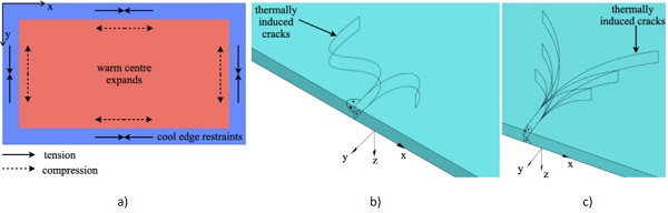
Due to the uneven in-plane heating of the glass pane(the gradient of the temperature over the thickness of the glass is almost negligible Pilette and Taylor1988), the warmer central area of the glass pane expands more than the comparatively cooler edge of the glass, which is equal to a restraint of the expansion of the warmer central area, as it can be seen in Fig. 1 a) on the left. These resulting unevenly distributed thermal strains (usually: positive strain at the edge of the glass - tension, negative strain in the centre of the glass - compression) can be translated into so-called thermally induced stresses with the help of the law of elasticity. Large in-plane temperature differences may lead the glass to fracture at the edge, as it can be seen exemplary in theclose-up views in Fig. 1 b) and c). This phenomenon can be caused not only by solar irradiance, but also by various heat sources, such as in the case of fire, where the glazing must be able to withstand high temperatures and high thermal radiation depending on the installation situation.
In the current state of standardization, only the French standard NF DTU 39 P3 (2006) exists in Europe, which enables the design of glazing with regard to thermally induced stresses. There, differentsimplified one-dimensional calculation methods are provided that enable the engineer to design with regard to the avoidance of thermally induced glass edge breakage. In the Italian guideline CNR DT 210 (2013), boundary conditions for the calculation are proposed and a temperature calculation procedure for double insulating glass units (DGU) is provided. Various leaflets of different countries, like Glass & Glazing Association of Australia AGGA (2015), Flachglas Schweiz AG (2021) and Verband Fenster + Fassade e.V. (2012) can be found on this topic, but in these leaflets only information on the phenomenon itself can be found, but no boundary conditions or methods for the thermally induced stress calculation are given there.
In a few older publications such as Mai and Jacob (1980), Pilette and Taylor (1988), but also in more recent publications such as Chen et al. (2017), Hildebrand and Pankratz (2013), Kozlowski et al. (2018), Montali et al. (2020) and Polakova et al. (2018), the topic of glass edge fracture of facade glazing induced by direct solar radiation was considered. In other publications with the background of fire behaviour of glazing Cuzzillo and Pagni (1998), Dembele et al. (2012) and Tofilo and Delichatsios (2010), the topic of thermally induced glass breakage was also considered. Although these publications already describe the relationship between the non-uniform temperature distribution and the resulting thermally induced stresses in the plane of the glass pane, only in Polakova et al. (2018) currently used calculation methods, including the approach of various meteorological data, are discussed in more detail.
For the above-mentioned re asons, a research project, which is described in Ensslen et al. (2022), investigates different meteorological conditions as well as state-of-the-art glazing in more detail. In the context of the publication presented here, the basics of numerical modelling for the thermal calculation of insulating glass units are described. In the next step thecalculation of the thermal transmittance Ug of the insulating glass unit is used to validate the model. Subsequently, initial calculation results on the thermally induced glass edge stresses of double and triple insulating glass units ( DGU and TGU) are presented using realistic and artificially generated meteorological data to present the range in which thermally induced stresses can arise. For the calculations, half-sided shading of the glazing is assumed (as an example) in order to take into account a shadowed situation, with reference to NF DTU 39 P3 (2006) and to additionally clarify the results using the temperature and stress plots presented later.
2. Heat transfer mechanisms
The transfer of heat, as a form of energy, takes place through the three mechanisms: heat conduction, convection and radiation. According to the second law of thermodynamics, energy always is transferred, from the warmer to the colder region for every transfer mechanism (Verein deutscher Ingenieure VDI e.V. 2013).
2.1. Heat conduction
Heat conduction describes the transfer of energy within a material that is exposed to a temperature gradient. In this process, energy is transferred from molecule to molecule through the movement of the molecules (oscillation and impact processes). Heat conduction is not necessarily bound to the solid state of aggregation and can therefore also take place in liquids and gases. With the help of Fourier's law (Jean Baptiste Joseph Fourier around 1822) (Verein deutscher Ingenieure VDI e.V. 2013), the heat transfer or heat flux density 𝑞̇conduction [W/m²] through heat conduction can be calculated, as shown in Eq. 1 for the one-dimensional and steady state case ( time independent) . The so-called thermal conductivity λ [W/(m K)] is used as a proportionality factor, which is assumed to be constant and isotropic for all further considerations. The temperature T₁ is the temperature of the warmer surface, while the temperature T₂ is the temperature of the colder surface. The thickness over which heat conduction occurs is taken into account with d.

In the case, when boundary conditions may change with the parameter timet ( e.g., solar irradiance or outdoor temperature), a transient analysis can be useful. Therefore, the transient heat conductionequation, which is given in Eq. 2 (Stephan 2013) for the three-dimensional case applies.

Equation 2 shows the dependence of the temperature T, time t, location x, y and z, thermal conductivity λ, specific heat capacity cp [J/(kg K)] and density ρ [kg/m³]. For the thermal calculations presented later, these input variables are defined in Section 5.
2.2. Convection
Convection describes the heat transfer between fluids (liquids and gases) and solids and contains the part of heat conduction. Convection could therefore also be simplified formulated as heat conduction, which is intensified by the flow of the medium. This connection will become clear later in Section 4.2 with the help of Equation 9. If the flow velocity of the medium is zero, no convection takes place and the medium transports heat only by the mechanism of heat conduction (see Section 2.1). In addition to the flow velocity, other parameters such as the temperature of the flowing medium and the surface roughness and temperature of the solid can also influence the heat transfer by convection. The heat flux density due to 𝑞̇convection [W/m²] can be calculated in a simplified way as shown in Equation 3 (Verein deutscher Ingenieure VDI e.V. 2013) and applies for the steady and transient state.
![]()
Here, hconvection [W/(m² K)] describes the convective heat transfer coefficient, whose size depends on the usually temperature-dependent material properties of the flowing medium, the flow velocity of the medium and the surface roughness of the solid in contact with the flowing medium. The temperature TSurface represents the surface temperature of the construction (e.g., glass or frame surfaces), while the temperature TBulk takes into account the temperature of the environment (outside or inside temperature). For external surfaces, the convective heat transfer coefficient hconvection,outside can be calculated in a simplified way according to EN ISO 6946 (2017) as a function of the wind speed v [m/s] using Equation 4.
![]()
For the glass surfaces surrounding the cavity of an insulating glass unit, the convective heat transfer coefficient hg,k can be calculated according to EN 673 (2011) depending on the gas properties and the temperature differences of the glass surfaces. The calculation of hg,k is explained in more detail in Section 4. For the convective heat transfer coefficient on interior surfaces hconvection,inside = 3.6 W/(m² K) , as proposed in EN 673 (2011), can be used. Further considerations on the convective heat transfer coefficient can be found in Jelle (2013).
2.3. Radiation
Heat transfer by radiation is caused by electromagnetic waves, which do not require a medium for propagation. In the case of radiative heat transfer on glazing, a distinction should be made between heat input and heat output by radiation. The direct solar irradiance on the glazing represents the heat input, which depends on the luminous and solar characteristics of the glazing: absorption α [-] , reflection ρ [-] , transmission τ [-] and emissivity ε [-] . The quantities just mentioned are additionally dependent on the wavelength of the incoming radiation. With the help of EN 410 (2011), the solar direct absorptance αe [-] of each glass pane can be calculated, which indicates how many percent of the incoming solar irradiance I [W/m²] is effectively absorbed by the glass pane. The energy input (heat flux density 𝑞̇direct,irradiance) into a glass pane due to direct solar radiation can be calculated if the solar irradiance and the solar direct absorptance αe are known, as described in Equation 5.
![]()
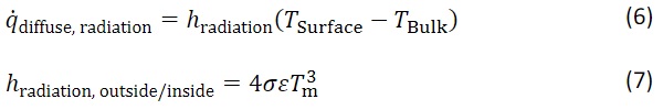
At the same time, the emissivity ε of each glass surface is relevant for the heat exchange, as the emissivity indicates how much of the heat energy can be released to the environment as diffuse radiation 𝑞̇diffuse, radiation. The heat exchange by means of diffuse thermal radiation goes back to the Stefan-Boltzmann law and can be formulated in a simplified form as shown in Equation 6 (applies for steady and transient state), where the emissivity ε of the surface (here outer/inner surface of the glazing) is included in the radiative heat transfer coefficient hradiation,outside/inside [W/(m² K)] and may be calculated with Equation 7 (see EN ISO 6946 2017).
In Equation 7 the temperature TSurface represents the surface temperature of the construction (e.g., glass or frame surfaces), while the temperature TBulk takes into account the radiant temperature of the environment. In Jelle (2013) further information is given regarding the radiative heat transfer coefficient and the wavelength-dependent quantities of absorption, reflection, transmission and emission. For the surfaces of the glass surrounding the cavity of an insulating glass unit, the radiative heat transfer coefficient hrad can be calculated according to EN 673 (2011) as a function of the emissivities of the glass surfaces surrounding the cavity. The calculation is discussed in more detail in Section 4.
Regarding the temperature difference of the bodies exchanging heat by means of diffuse radiation, it should be noted that the surface temperature of the glazing and the bulk temperature (also radiant temperature) are combined by the mean temperature Tm (arithmetic mean of TSurface and TBulk). This approach is based on the fact that the surface temperatures of the considered bodies exchanging radiant heat are not too different. The radiant bulk temperature depends on the inclination (e.g.,vertical) of the glazing, as the inclination of the glazing results in a different viewing factor to the surrounding external surfaces. E.g., a horizontal roof glazing “sees” more of the sky and less of the rest of the surroundings, while it is correspondingly the other way round for a vertical glazing.
Since vertical glazing is considered in the studies presented here, the assumption that the radiation bulk temperature of the surroundings and of the outer glass surface are not too different is approximately justified. When considering horizontal glazing, it is important to look closely at the radiant bulk temperatures of the surfaces involved (sky and glazing), as in particular the sky temperature on a cloudless day can be as low as - 20 °C (regardless of the time of year) (Maroy et al. 2017), while at the same time the ambient temperature on a summer day in Europe can be between 30 °C and 40 °C based on experience.
3. Description of the investigated glazing
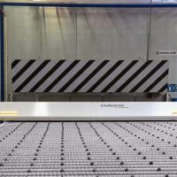
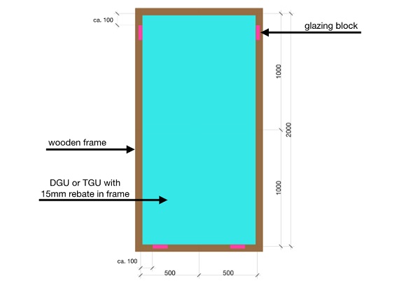
For the investigations presented here, double and triple insulating glazing (see cross-sections through the frame in Fig. 3a and 3b) in southern orientation (azimuth 180 °) as vertical glazing are considered. The dimensions of the glass panes were chosen to 2000 mm x 1000 mm (see Fig. 2), whereby the glazing is assumed to be so-called standing glazing (see glazing blocks in Fig. 2). The glazing blocks have usually a length of around 100 mm and are installed with a distance from the corner of the glass of around their length. The exact position of the glazing blocks is not specified, as these are later neglected in the numerical simulations for simplification.
Each glass pane is assumed to be monolithic with a nominal thickness of 4 mm. For the cavities of the insulating glass units, which would be filled with an argon-air mixture (90% argon, 10% air), a distance of 16 mm is chosen, which is common in practice. At the edge of the cavities, an edge pacer of the so-called warm edge technology with polysulphide sealant is used. A simplified wooden frame (base frame taken from EN ISO 10077-2 Annex H Figure H.5 2017) with a light colour (assumption αe,frame = 0.2) and relatively good thermal insulation properties (thermal transmittance of Uf≈ 1.4 W/(m2 K) - further investigations on currently used window frames can be found in Baldinelli et al. 2020) is assumed for the framing of the insulating glass. The glass rebate in the wooden frame is assumed to be 15 mm, whereby a 3 mm thick EPDM (ethylene-propylene-diene monomer rubber) sealant is assumed at the juncture between the wooden frame and the glass (see Figs. 3a and 3b).
The basic values of the material properties were taken from EN ISO 10456 (2007) and EN 572-1 (2016). For the warm edge spacer, the equivalent thermal conductivity for the 2-box model (Svendsen et al. 2005) was taken from an information sheet (Bundesverband Flachglas e.V. 2013). The density ρ and specific heat capacity cp of the edge spacer were averaged via the cross-sectional area. The material properties used in all numerical simulations can be found in Tables 1 and 2.
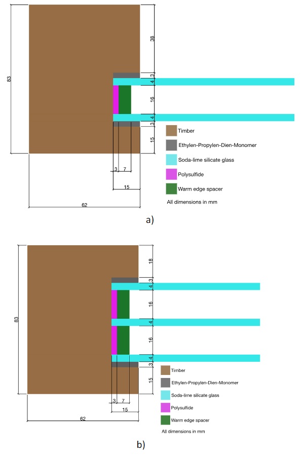
Table 1: Material properties used for thermal steady state and transient simulation, taken from a) EN ISO 10456 (2007), b) EN 572-1 (2016), c) Bundesverband Flachglas e.V. (2013) and d) averaged via cross-sectional area.
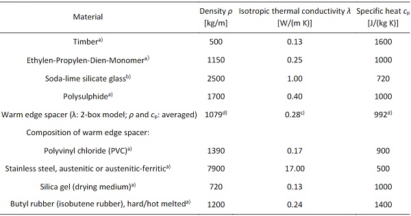
Table 2: Material properties used for mechanical simulation, taken from EN 572-1 (2016).

4. Modelling of heat transfer in cavity and calculation of thermal transmittance (Ug) for a triple insulating glass unit (validation of model)
Before the thermal-mechanical calculations (Section 6) can be conducted, it must first be checked whether it is possible to model the thermal behaviour of an insulating glass unit using commercial finite element software by just using solids (no fluid dynamics). In particular, the question arises how the heat transfer in the cavity between the glass panes can be modelled, since here, compared to all other areas of the glazing, a fluid and not a solid is present.
A fluid dynamic simulation of the thermal behaviour of the gas in the cavity would probably reflect the heat transfer by convection taking place there with the best accuracy, but is not practical for an engineering application. For this reason, it was decided to model the heat transfer in the cavity using convection boundary conditions with combined heat transfer coefficients (superposition of radiation and convection). In doing so, the effects of fluid flow due to convection are taken into account in a simplified way. This engineering approach is based on the procedure in EN 673 (2011), which is the basis for the calculation of the thermal transmittance Ug.
As already described in Section 2.2, convection is influenced by the flow velocity of the gas in the cavity between the glass panes. To avoid complex calculations to determine the flow velocity, the so-called Nusselt number Nu can be used. This dimensionless characteristic number describes the ratio of the heat transfer mechanisms of convection to conduction (Nu= qconvection / qconduction) and thus describes how much greater the heat transfer of the heat conduction is increased by the fluid flow. This results in the physical limit value of Nu = 1 for the Nusselt number, which describes the condition that the heat transfer mechanisms of conduction and convection are to be regarded as equivalent.
In this state, the heat transfer in the cavity can be represented either by conduction or convection. At the same time, heat radiation must also be taken into account to complete the heat transfer phenomenon within the cavity. If the Nusselt number is larger than one, the heat transfer by means of heat conduction is amplified by the fluid flow. This phenomenon could be described as an increased heat conduction, which can be physically represented with a convection boundary condition. If the calculation of the Nusselt number (for given temperature difference between the surfaces of the cavity) results in Nu< 1, Nu= 1.0 must be set (EN 673 2011). Values for Nu< 1 would be equivalent to a negative flow velocity, which is physically impossible. In the case of Nu < 1, heat transfer in the cavity takes place by means of thermal conduction and radiation, whereas for Nu≥ 1, heat transfer takes place by means of convection and radiation.
In order to check whether the approach chosen here (heat transfer in the cavity by means of convection boundary conditions with combined heat transfer coefficients) can be validated, the thermal transmittance Ug of a triple insulating glass unit was calculated using finite element software and finally compared with the manual calculation according to EN 673 (2011). For this purpose, a thermal steady state analysis with constant boundary conditions is carried out on a finite element model and the heat flux density in each glass pane is evaluated. Subsequently, the thermal transmittance Ug can be calculated using the numerically determined heat flux density in the glass and the present temperature difference between inside and outside. The boundary conditions and the calculation are described in Sections 4.1 and 4.2.
4.1. Thermal boundary conditions on the outer and inner surface for thermal transmittance (Ug) calculation
The thermal boundary conditions for the outer (outside of the building skin) and inner (inside of the building skin) surfaces of the insulating glass unit are taken from EN 673 (2011). It should be noted that the heat transfer coefficients provided there represent a superposition of the heat transfers of radiation and convection. The external heat transfer coefficient is composed of a convective part of hext., conv. = 20 W/(m² K) and a radiative part of approx. hext., rad. = 5 W/(m² K), which results in a combined heat transfer coefficient of hext. = 25 W/(m² K) on the external surfaces (see EN 673 2011).
This composition can be traced by the information given in Table 7 of EN ISO 6946 (2017). The internal heat transfer coefficient is composed of the convective component of hint., conv. = 3.6 W/(m² K) and, depending on the emissivity of the glass surface, a radiative component of hint., rad. = 4.1 W/(m² K) (for an emissivity of εglass,uncoated = 0.837 see EN 572-1 2016), resulting in a combined heat transfer coefficient of hint. = 7.7 W/(m² K) on inner surfaces (see EN 673 2011). The superposition of the convective and radiative parts of the heat transfer coefficient is based on the assumption that the radiation bulk temperature of the environment is similar to the bulk air temperature (see Section 2.3). With the help of this assumption and the similarity of Equations 3 and 6, the heat transfer coefficients for radiation and convection can be superposed and used in a convection boundary condition (separately for the outside and inside of the glazing).
The bulk temperature of the convection boundary condition on the outer surfaces is chosen to Text. = 5 °C, while for the interior surfaces the bulk temperature was chosen to Tint. = 20 °C, which results in a temperature difference of ΔT = 15 K from inside to outside according to EN 673 (2011). In summary, the following thermal boundary conditions result on the outer and inner surfaces for the thermal transmittance (Ug) calculation:
- External combined heat transfer coefficient, constant: hext. = 25 W/(m² K) with constant external temperature of Text. = 5 °C as convection boundary condition,
- Internal combined heat transfer coefficient, constant: hint. = 7.7 W/(m² K) with constant external temperature of Tint. = 20 °C as convection boundary condition.
4.2. Thermal boundary conditions on glass surfaces surrounding the cavity for thermal transmittance (Ug) calculation
To take into account the heat transfer through the cavity, the equations of EN 673 (2011) are used to determine the combined (radiation and convection) heat transfer coefficient. For the two cavities of the triple insulating glass unit, the assumption is made that thermal insulation coatings (emissivity ε₃,₅= 0.0352) are applied on positions 3 and 5. Positions 2 and 4, with an emissivity according to EN 572-1 (2016) of ε₂,₄ = 0.837, are not coated. The numbering of the positions can be understood from Fig. 5. This results in an identical constellation of emissivities for both cavities and, as can be seen from Equation 8 (EN 673 2011), also the same radiative heat transfer coefficient.
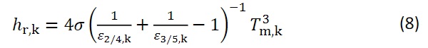
Where:
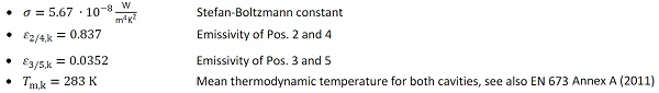
The radiative heat transfer coefficient is calculated with the help of the assumed input values to hr,₂/₃ = hr,₄/₅ = 0.17 W/(m² K).
The convective heat transfer coefficient hg,k for both cavities will be calculated in line with the formulae and boundary conditions given by EN 673 (2011), whereby it is assumed that the cavity is filled with 90 % argon gas and 10 % air. To determine the convective heat transfer coefficient, the Nusselt number is required, which, under the given boundary conditions by EN 673 (2011), is calculated to Nu≈ 0.85 and is set to Nu= 1 by the limit condition. Based on the calculated Nusselt number (Nu = 0.85 < 1), it can be concluded that for the temperature condition described in EN 673 (2011) (Text. = 5 °C und Tint. = 20 °C), heat transfer in the cavity does not take place by means of convection, but rather via heat conduction due to the low Nusselt number.
In this sense, the idea could arise that the heat transfer through the cavity can be modelled with a volumetric body with a volumetrically averaged thermal conductivity (𝜆cavity= 1.7652∙10⁻²W (m K)/for the gas mixture assumed here, 90 % argon and 10 % air filling). With this approach, however, it would no longer be possible to take thermal radiation into account and incorrect results would follow. For this reason, a convection boundary condition is used to model the heat transfer in the cavity, which contains the combined heat transfer coefficient (radiation and convection). Finally, the convective heat transfer coefficient hg,k according to EN 673 (2011) can be determined using Equation 9.
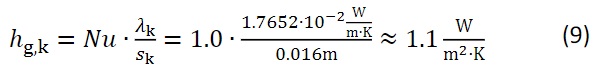
The combined heat transfer coefficient for the cavity of the triple insulating glass unit is finally obtained by the superposition of radiation and convection (hr,₂/₃ = hr,₄/₅ = hr,cav. = 0.17 W/(m² K) and hg,k = 1.1 W/(m² K)) to hcavity = hr,cav. + hg,k = 1.28 W/(m² K). For the thermal transmittance calculation of the insulating glass all required input values are now available.