
This paper was first presented at GPD 2019 by Agnes Koltay from Koltay Facades.
Bio: Agnes has MSc in Architecture and MSc in Façade Engineering. Her keen interest in high-rise engineering and glass design lead her around the world. She worked with award winning architects and multidisciplinary global engineering firms prior to founding Koltay Facades in 2011 in Dubai. The company specializes in façade engineering consultancy and work on worldwide projects from their Dubai and Singapore offices. Projects include high-end high-rise buildings around Burj Khalifa area such as Burj Vista, Sky View, Fountainviews, complex shaped buildings such as Museum of The Future and The Opus, and landmark projects such as MOL Tower in Budapest.

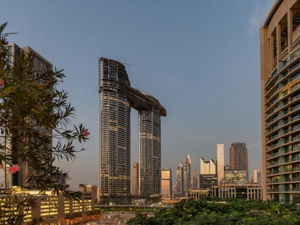
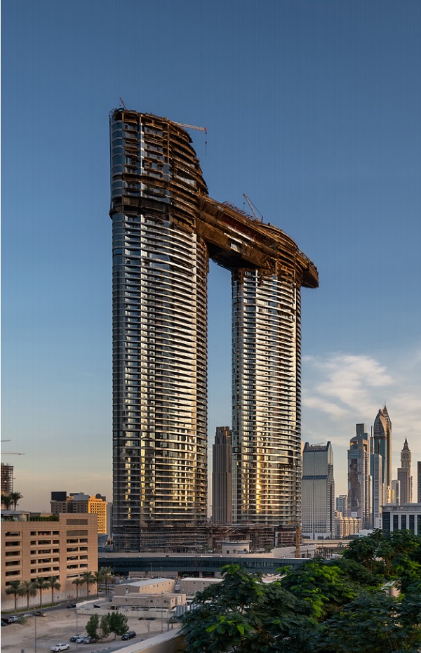
Sky View is a twin tower development with skybridge and skywalk observation deck located in Downtown Dubai, close walking distance from Burj Khalifa. The concept was initiated in 2008 but intense design work commenced only in late 2013, with site woks starting in early 2015. The building is scheduled to be handed over by end of 2019.
The towers are 61 and 57 floor in height, reaching 264 meters. The skybridge is located at floors 51-54, and the skywalk tourist feature at floor 53-54. The development includes 5star hotel rooms (Address Hotel brand), serviced hotel apartments, Skycollection penthouse residential units, food and beverage outlets, select retail space, tourist attractions and rooftop bar with dedicated elevator link.
Sky View is developed by Emaar. The design architect was SOM from Chicago, the lead consultant is Norr Group. Koltay Facades provided façade engineering consultancy and façade access strategy consultancy from the early design stages to handover. Structural engineering and MEP also by Norr Group. The main contractor is ACC – Arabian Construction Company, while the façade package was shared in between Folcra Beach and Al Ghurair Aluminium, with a number of further specialist companies and cladding subcontractors involved. The tensioned glass walls were built by Novum Structures. The tower glass is SS 20, supplied by Guardian Glass, the stainless steel cladding is 6WL from Rimex. The system profiles are supplied by Technal, specifically developed for this project. The BMU system is supplied by Cox Gomyl.
As for each consultancy project, we started with categorizing the façade systems for easy reference. It is advisable to use similarities for grouping in order to avoid too many system types, and usually 4-8 systems should cover a tower. For Sky View, while we had only 7 system types and 2 balustrade types for the towers, additional 11 façade system types and 2 balustrade types were used to describe the entire development including the skywalk, the pavilions, the podium.
Value engineering is often taken as a simple cost reduction exercise executed at the very end of the design stage of the projects. This generally results into unpleasant compromise on the building aesthetics, with eliminated decorative features, simplified geometry, substitute materials and similar. It is utterly important that cost efficiency items are considered throughout the design process, to bring the resulting tender design within budget.
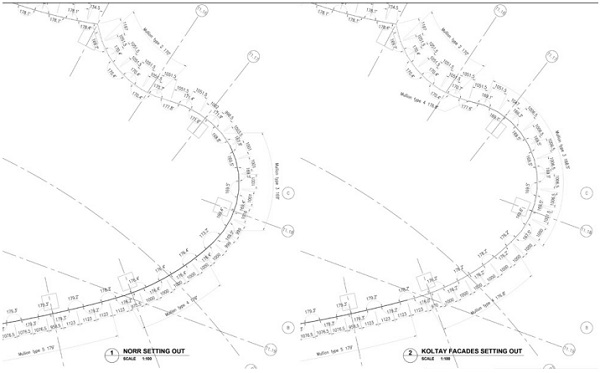
The first of many of those cost efficiency improvements is an assessment of the geometry and modulation. For Sky View, the original architectural floorplan geometry required 14 different extrusions, considering that male-female unitized extrusions can take up as much as 2.5 degrees angular change. By altering the merging points of arcs, slightly changing radiuses and amending the modulation, the final solution looks almost identical to the original outline, but requires only 10 different mullion extrusions. (Image 1- Setting out comparison)
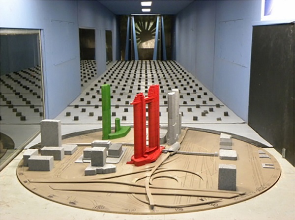
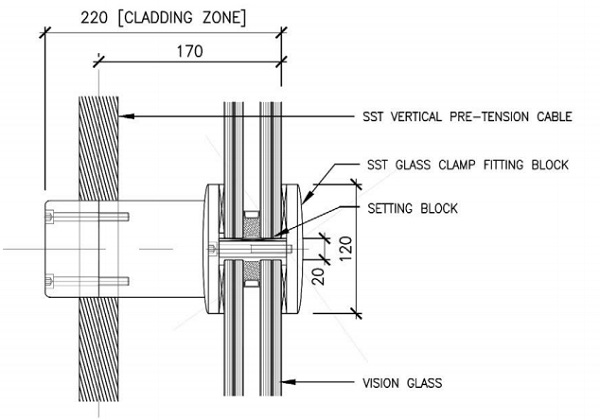
An other important optimization exercise to analyze the wind tunnel test results and translate it to the most optimal framing member sizes and glass thicknesses. While for mullions a typical value could be selected with local reinforcing or additional bracketing at local high pressure spots, glass is usually designed for the highest pressure, to provide visual uniformity all over the project.
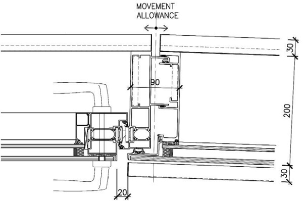
For Sky View however, the glazing thickness was primarily driven by acoustic requirements, and glass thicknesses optimized for that. The planar step of different assembly types can be offset by varied air gap size, adaptor profiles or special mullions. At this stage of the design, the cladding zones (distance from external side of glass to edge of concrete slab) were finalized and the required slab outline communicated to the structural engineer.
The typical tower system is pressure equalized male – female unitized system, with solid stainless steel sheet infill elements and glazing. The implemented system design had high level of similarity to our tendered design. The balcony doors are outward opening side hinged doors, to enable facetation as the building geometry requires. The door frames are externally concealed by flush glazing, the door hardware is drilled through the glazing.
However, some doors are located at very narrow parts of the uneven width balconies, and had to be inward opening. This brought a challenge to system design, where flush glazed concealed frame, high level of watertightness and inward operation was simultaneously required. The implemented solution is less integrated to the fixed frames as intended, but still have relatively slim appearance.
The top few floors of each tower give visual continuation of the towers above the skybridge levels. However, the floor plate outline changes and each floor has a different geometry. Maintaining the unitized system here is impractical, as the new geometry would necessitate additional extrusions to deal with tighter radiuses. Furthermore, the area is easily accessible from the skybridge roof level, via scaffolding. These top floors are more like “pavilions in the sky”. These structures were clad with stick system curtain walling, while maintaining the visual match to the tower areas below.
There are two main areas of the building with patch fitted glass wall. The panoramic elevator shaft is installed over architectural steelwork, while the two elevations of the ground level lobby are installed over a one -way tensioned cable net. With those cables spanning almost 20 meters, the reaction forces on both sides are large. These needed to be precalculated and coordinated with the structural engineer to ensure that they are accommodated by the interfacing main structure.
The skywalk area is a giant steel truss itself, with glazing on all sides. The perimeters of the floor area are solid filled, just to cater for a wider audience – some may feel discomfort with fully glazed floor area. The floor glazing has high level of redundancy, consisting of 5 layers of glass laminated with SGP in an IGU assembly. The double glazing improves thermal performance and reduces cooling loads, as well as ensures clear view with no condensation even on those days when the outside air temperature drops below dew point and humidity is high.
The skybridge itself has a 3 story tall trusswork primary structure that was assembled on ground and elevated in position by hydraulic jacks. The main, 80 meters long portion of the bridge was a single 165 tonnes lifting operation over about a week time. The bridge will house residential units and have an infinity pool on top. The bottom side of the bridge is clad with solid stainless steel sheets.
During a late design review, just after procurement of the façade package had started, further decorative flying beam features were added to the building. These give the appearance of certain spandrel zones departing from the tower to smooth the visual transition towards the skybridge and skywalk. While architecturally well placed, the late change introduced complexity on the façade access strategy, by blocking access of the intended BMU machines to the areas below the fly beam features.
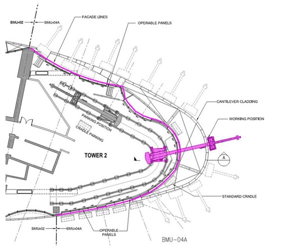
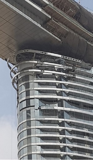
This necessitated modification of the strategy and further BMU units and accessories. The dense bridge truss limited the overall sizes of the BMU machines placed at level 50, below the bridge belly.
The machine and its counterweight could not increase further, however the added extendable pentograph cradle that was needed to reach below the fly beam features necessitated further measures of stabilizing. The machine track was then brought closer to the facades to reduce reach, by rearranging the layout.
An other interesting area for cleaning and maintenance access is the skywalk. The bottom side is reached by monorail system.
The sides have an 800 mm external walkway with upper rail for safety and for spare glass manipulation. The roof glass is walkable for cleaning. For reglazing, a small custom built sliding gantry is provided that needs to be assembled and after use disassembled and stored away.
This gives a brief introduction to Sky View’s façade package design and procurement process. The building will soon be ready to welcome visitors as a highlight of Dubai Downtown.


Comments
To avoid having too many different types of systems, it is best to group them according to similarities. Typically, a tower should be covered by 4–8 systems.