This paper was first presented at GPD 2023.
Link to the full GPD 2023 conference book: https://www.gpd.fi/GPD2023_proceedings_book/

Author:
- Sandra Kugler - Viprotron GmbH
Technology
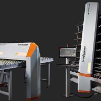
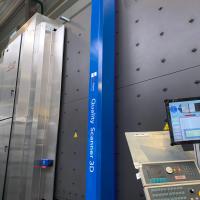
Since 2004 Viprotron is focusing on line scan cameras and specialized illuminations for different optical problem areas in the architectural glass industry. The Quality Scanner 3D with the brightfield channel for defects according to the standards (EN 1279 I, ASTM C1036, etc.), the darkfield channel for low contrasted defects or „white haze“ and the reflection channel for coating defects are the benchmark for the industry since 2012.
In 2017 Viprotron was the first to launch an Anisotropy Scanner, which was awarded then to be the „most innovative equipment“ by the American Glass Magazine.
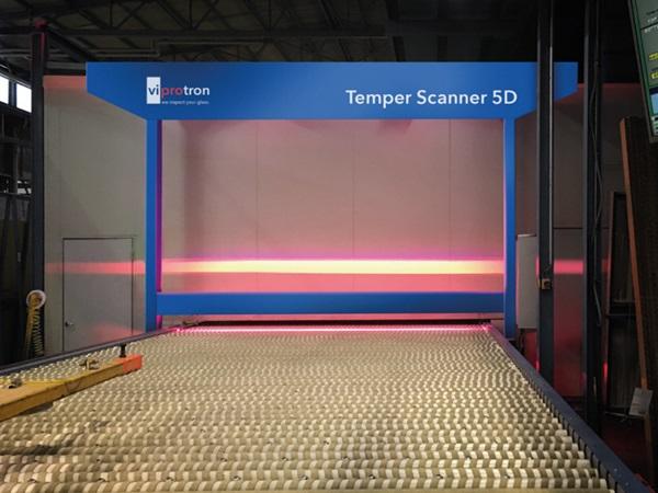
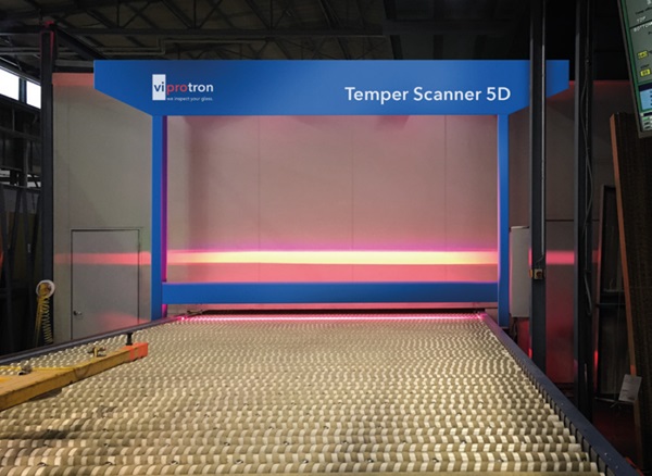
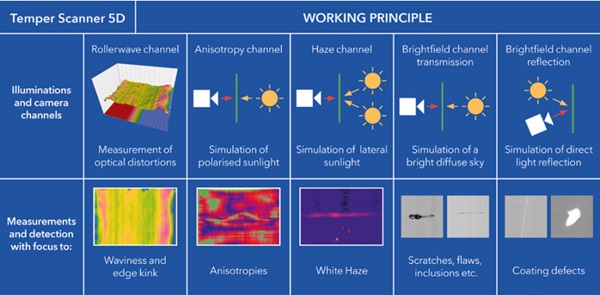
With the Temper Scanner Viprotron now launched a completed scanner with a missing function in our product range: the measurement of rollerwaves & edge kink at the exit of a tempering furnace. Together with the other already existing proven functions Viprotron now provides a modular scanner system, which can be equipped with up to five detection channels depending on the needs of the customer:
While the channels 1 – 3 cover typical furnace related issues and are the base for the optimization of furnace parameters, the channels 4 + 5 can look for typical glass defects, in case there is no earlier possibility for a quality control in the workflow. All channels can be combined or used as a single channel, depending on what the customer really wants to control after the furnace. All combinations are possible.
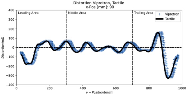
Roller wave & edge kink measurement
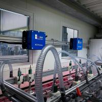
It is no news: the more exact the data are for a decision, the better is the result! That´s why equipment and machines became more precise over the years. The Temper Scanner 5D is a good example for this. Developed by Viprotron as a modular scanner with a new level of roller wave measurement as a base, it combines smart state of the art line scan camera technology with a continuous optical triangle light reflection pattern. This allows for highest spatial resolution: In transport makes it easy to use, nor a special exit conveyor which makes it easy to assemble even as a retrofit. The line scan cameras only need gaps between the rollers, which normally exist.
Anisotropy measurement
As first supplier in the architectural glass market in 2017 Viprotron realized an anisotropy measurement function in a completely new type of scanner. The need of such a scanner was obvious: Claims appeared because there was no standards in the industry and the quality level in terms of anisotropies was discussed only after the final customer saw the delivery quality in his façades. To be able to measure the anisotropies, define a certain quality level and gain a process stability to achieve this, an objective measurement tool was needed. Viprotron had such a tool and was part of the team helping to set up the needed standards. In the meantime these standards are existing (ASTM C1901 21 or DIN SPEC 18198). Now there is much more understanding in anisotropies themselves, the appropriate scanner equipment and the quality levels that can be achieved.
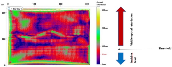
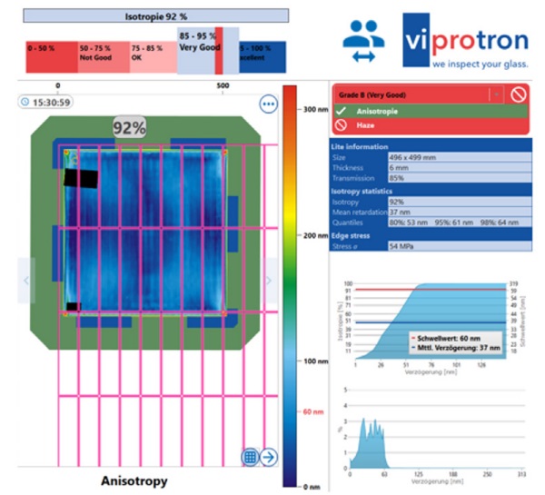
The Viprotron Anisotropy Scanner function measures the light intensity differences in the glass which appear when glass contains anisotropies. With these values as a base it calculates the optical retardation in nanometers (nm) according to special mathematical models. These models provide exact values with a tolerance of less that seven nm, what is well within the standards, which require less than ten nm.
The results can be displayed in a percentage of the overall „good“ area according to a given threshold in nm, from where on the anisotropies become visible for human eyes. A second display version can show the mean value per lite, which can be defined without using a threshold.
As the intensity of anisotropies is normally high at the edges, corners and possible holes, those areas can be faded out when evaluating the quality, because when finally framed, the corner and edge values are of little interest. The anisotropy function comes with several further analysis tools, which are described in the last chapter of this article.
White Haze detection
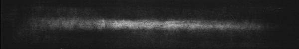
Known as „Skunk Marks“ or under other names, the „White Haze“ effect coming e.g. from uneven rollers or from glass bowed in the furnace, which runs only on the middle or the edge sections of a lite, when traveling through a flat glass furnace, depending whether bowed concave or convex. Then all the glass weight lies on these parts of the glass and leaves a surface contamination. Under normal production conditions this is difficult to detect and normally will only later be seen on a scanner of an IG line or finally in the construction place.
The typical way of finding low contrasted area defects like roller marks, white haze etc. is with a darkfield channel. Viprotron uses this technology since 2004 to detect even hairline scratches and all other low contrasted defects in architectural glass. The idea is to show the areas of white haze directly when the respective glass is exiting the furnace, so that the operators are alarmed, can easily find these contaminated areas and polish them out. Depending on the complete setup of the planned Temper Scanner, this option can be added as darkfield in transmission (illumination underneath the conveyor) or as darkfield in reflection (illumination above the conveyor).
Brightfield in transmission
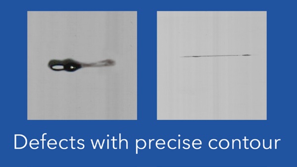
In some production workflows there is no good chance to control the glass for quality issues or the furnaces are the focal point, where glass comes together from many different machines to be checked against the quality standards (like EN 1279). Then the idea is not to spend money for scanners on the many single machines, but concentrated on a control after the furnaces. Like each medal, the decision to check the glass quality here has a second face: The best place to check glass for quality is not after a furnace, but after a washer to avoid pseudo defects. Using the brightfield channel, only high contrasted defects with normally a clear contour will easily be detected even after a furnace. Examples are scratches, or raw glass defects like inclusions or bubbles.
Brightfield in reflection
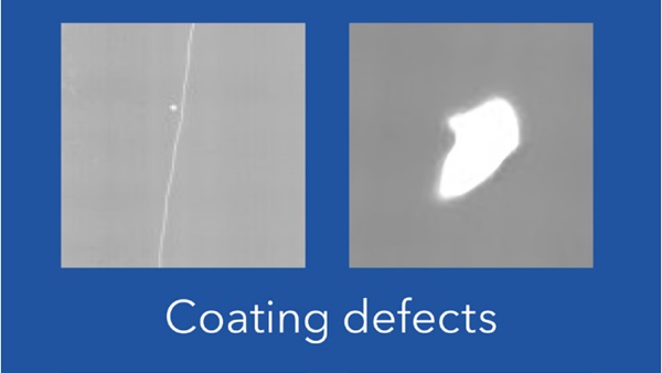
The number of temperable coatings is rising yearly. Of course typical coating defects like scratches or voids can be detected after a furnace as well. That´s why Viprotron decided to make such a channel available at that place of control.
The reflection channel is not only good to detect coating defects, but to improve the data volume for a better defects classification. The more data from different channels are available for a certain area, the better the classification can be, basing on precise repeatable objective measurements, and not on undefined data collections coming from different sources.
Base for process optimization
Using all availble channels, the Temper Scanner 5D is the most complex scanner type in the architectural glass market. As mentioned earlier, it doesn´t only provide the chance to collect as many precise data as possible, but even in this product development stage it already provides tools for an analysis of these data and tools for using these data with relation to the furnace structure / setup. The components of the heating zone and the quench can be put over the furnace bed as a separate layer, to easily find out the reasons for certain issues in or on the glass. The analysis tools and additional views provided by the separate channels then allow a quicker optimization of the furnace parameters. While the first three mentioned channels / functions target on the improvement of the furnace parameters, the last two give a base to find the root cause for defects in the processes before tempering. As mentioned before, a complex scanner to help in all quality questions including tempering.