This paper was first presented at GPD 2025.
Link to the full GPD 2025 conference book: GPD_2025_ConferenceProceedingsBook.pdf

Authors: Céline Guermeur a, Eric Shomo a, Heinrich Ostendarp b, Mauri Saksala c
a. Corning Incorporated, USA
b. Hegla GmbH & Co. KG, Germany
c. Glaston Oy, Finland
Abstract
Comprehensive solutions for the processing of half-jumbo size ultra-thin boro-aluminosilicate glass (below one millimetre in thickness) in architectural glazing manufacturing are now available. This paper will cover the fundamental equipment and process differences for handling, cutting, and manufacturing of architectural glazing and laminates with fusion-drawn boro-aluminosilicate glass versus thicker soda lime silicate glass. Topics include glass cutting behaviour and edge strength as a function of cutting parameters, controlled and automated glass handling along the process flow, equipment design for glazing manufacturing, and adaptation of existing clave lamination lines to process thin glass.
Article Information
- Published by Glass Performance Days, on behalf of the author(s)
- Published as part of the Glass Performance Conference Proceedings, June 2025
- Editors: Jan Belis, Christian Louter & Marko Mökkönen
- This work is licensed under a Creative Commons Attribution 4.0 International (CC BY 4.0) license.
- Copyright © 2025 with the author(s)
1. Introduction
From almost two decades more than 4 billions of square meters of boro-aluminosilicate glass less than one millimetre thick have been automatically processed for the manufacturing of various display products (LCD, OLED....) and automotive glazing. The typical drivers for ultra-thin glass use are to decrease final product thickness or weight, to increase the product performance, or to decrease the product’s carbon footprint.
Architectural glazing also benefits from the use of ultra-thin glass to help the world meet the growing demand for more energy-efficient and comfortable housing.
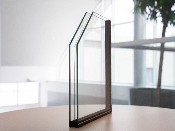
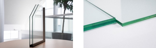
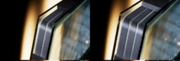
Figure 1 below provides two examples of architectural glazing products with ultra-thin glass (below 1 mm thick). These Insulated Glazing Units (IGUs) deliver higher thermal insulation, reduce cold air draft, are easier to transport, and are easer to install and operate compared to their conventional counterparts. The benefits of ultra-thin glass for architectural glazing will be described in more detail in the presentation “Higher performance and lighter IGUs with boro-aluminosilicate thin glass” at GPD this year.
Highly automated equipment compatible with ultra-thin glass for high volume manufacturing of architectural glazing has recently become more available to IGU manufacturers. Leveraging decades of experience in ultra-thin glass processing and handling along with extensive knowledge of the architectural manufacturing and laminating industry, comprehensive solutions from Glaston, Hegla, and Corning are now available for advanced IGU manufacturing. Automated lines are available to handle 0.5 mm and 0.7 mm ultra-thin glass, up to 3200 mm x 2246 mm, and are capable of unloading, cutting, sorting, washing, laminating, and manufacturing 0.4 to 0.6 million IGUs per year per line. This paper describes equipment design principles for ultra-thin glass and examples of available equipment designs based on these principles.
2. Equipment design principles for ultra-thin boro-aluminosilicate glass
The glass processing equipment modifications are driven by the following charateristics of Corning’s ultra-thin architectural boro aluminosilicate glass:
- It is a novel glass composition with a coefficient of thermal expansion of 3.2 x 10⁻⁶ /K (over the range 0- 300 °C).
- Half millimetre boro-aluminosilicate glass is respectively 6.3 times and 8.4 times lighter than 3 mm and 4 mm soda lime silicate glass. While a half-jumbo sheet of 3 mm soda lime glass weighs more than 60 kg, a 0.5 mm boro-aluminosilicate glass weighs less than 10 kg.
- Half millimetre thick glass is also 216 times more flexible than 3 mm glass.
This leads to a few key equipment design features that needs to be considered.
2.1. Crate and conveyance angle
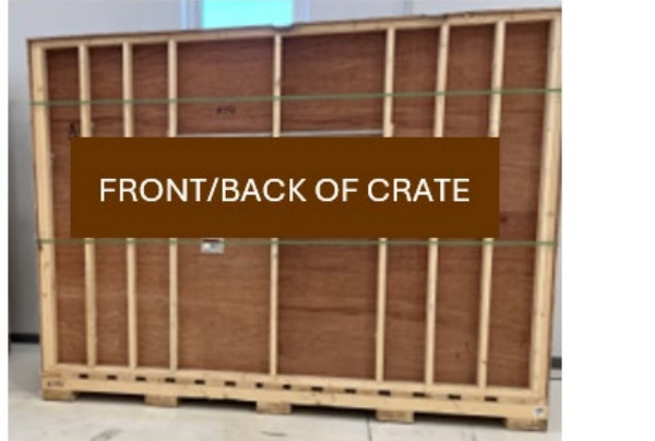
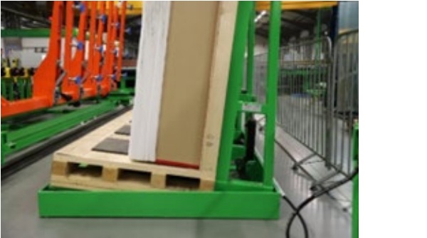
When processing ultra-thin glass, it is recommended to increase the crate tilt frame angle comparatively to standard soda-lime glass processing, due to the material being lighter and more flexible. Less force is required for displacement or bending which can be counteracted by the increase crate tilt angle. When unloading glass, the crates may be placed onto an L-frame with a minimum tilt angle of 15° from vertical. Commercially available crate tilters are a convenient option to position the crate to a suitable angle to prevent displacement or glass bending.
Standard soda-lime glass processing equipment can be adapted to suitably accommodate the ultrathin glass. Some examples of equipment modifications can include: (1) reducing the air flow on a float surface (e.g. cutting table); (2) improving table flatness (e.g. cutting table); or (3) increasing the tilt angle on vertical conveyor lines (e.g. IGU line). Considerations should also be taken into account when purchasing new equipment, such as material handling methods and equipment loading capacity, both of which utilize the advantage of the significantly lower weight of the ultra-thin glass.
2.2. Ultra-thin boro-aluminosilicate glass scoring and separation
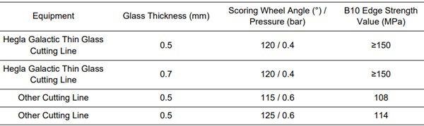
Common glass cutting and separation methods can be used to cut Corning’s ultra-thin architectural glass. The first step of the glass cutting process is a scoring process to form a median crack near the glass surface using a tungsten carbide or diamond scoring wheel. The second step is a breaking process where the scored sheet is separated along the median crack line by applying a tensile stress due to bending or local compression methods. Optimum scoring conditions are dependent on the glass composition, surface condition, and equipment parameter optimization. To separate boroaluminosilicate glass substrates with minimum breaking load and lateral cracking, a median crack depth of 100 μm is appropriate when the 100° angle wheel is used for scribing 0.5 mm ultra-thin glass. (Ono & Tanaka, 1999). For Corning’s ultra-thin architectural glass, we have found that the appropriate breaking load may also be obtained with a smaller wheel angle and lower pressure compared to thicker soda lime glass.
Table 1: Ultra-thin boro-aluminosilicate edge strength as function of wheel angle and pressure.
2.3. Glass inset
When using ultra-thin glass as a center pane in an IGU, it is recommended to inset the ultra-thin glass from the thicker glass panes. This limits the risk of out of plane bending of the thin glass during IGU or window manufacturing, which can lead to damage. There are multiple available solutions to implement this inset on IGU lines, and it provides the advantage that secondary seal can be applied in one pass, thus reducing takt time.
2.4. Asymmetric laminates
Boro-aluminosilicate glass, down to 0.5 mm, can be laminated effectively to soda lime silicate glass using standard nip roll lamination lines. Laminate assembly can be fully automated with Glaston’s newly developed concept tailored for ultra-thin glass processing with a specifically designed gripper that can handle both soda-lime glass and Corning’s ultra-thin architectural glass.
After assembly, laminates will be sent to a pre-heating chamber and a nip roll. Glaston has used its full convection laminating system to ensure that the asymmetric laminates can be heated efficiently and evenly. Full convection laminating technology also ensures a steady end result with any coating and interlayer type used. Other heating methods are possible.
When boro-aluminosilicate glass is laminated to soda lime glass, the resulting laminates have bow or warp due to the difference in coefficient of thermal expansion of the two glasses. There are currently three methods to mitigate the bow of the laminates:
- When using the nip roll plus autoclave process, using a horizontal cart during the autoclave process takes advantage of gravitational force to reduce bow in the final parts.
- When using a press-type laminator with heated and cooled platens, differential cooling can be used in the cooling step to minimize bow.
- Post-processing can be performed on laminated parts from the nip roll - autoclave process that are bowed. Heat and applied force (preferably gravity) can be used to mitigate bow.
Any of these three techniques have demonstrated the capability of producing low-bow laminates, depending on the type of lamination line that is being used. Since the most common lamination lines use the nip-roll and autoclave process, the horizontal rack method is especially applicable. It does not require a specialized laminator or autoclave and also does not require additional processing steps to mitigate bow.
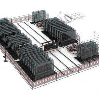
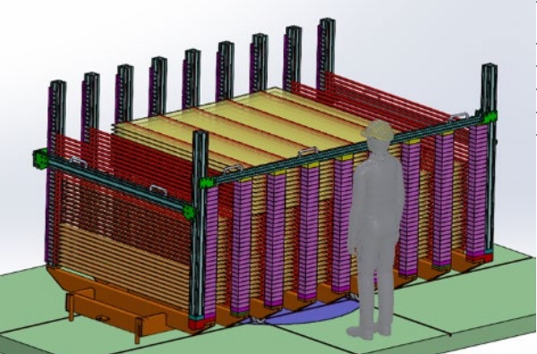
A horizontal type autoclave rack was used to collect the data from table 2 on a lamination line. The stackup was produced on a nip roll and then processed in an autoclave, either vertically on a conventional A frame, or horizontally on an horizontal cart (Figure 4).
Table 2: Bow Reduction Using a Horizontal Autoclave Cart.
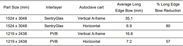
Note that bow was reduced for stacks with two common interlayers using the horizontal cart method. Bow reduction was greater on the larger parts, which is expected, and resulting panes are well within an acceptable level (< 3 mm/m) for IGU manufacturing.
This horizontal cart design can be customized to fit any autoclave based on part sizes and autoclave dimensions.
It has also been shown that asymmetric laminates of Corning’s ultra-thin architectural glass and soda lime glass can be cut using commercially available laminate cutting equipment.
With these recommendations and experience gained in various industries, automatic equipment to carry the whole IGU manufacturing process with ultra-thin glass have been developed and are now available for architectural glazing manufacturing.
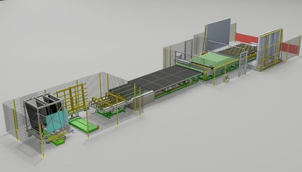
3. HEGLA’s process chain for ultra-thin glass
Starting with 0.5 mm or 0.7 mm ultra-thin raw glass supplied in special crates as already described, HEGLA offers the entire process chain right through to supplying the insulating glass lines with individually cut glasses. Depending on glass processor requirements and local conditions, existing machinery can also be adapted or extended to full automation.
3.1. Raw glass handling
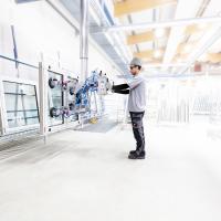
From an inclined position in relation to the vertical, the raw glass sheets are removed fully automatically and gently from the boxes, tilted, and fed horizontally to the cutting system. This is done by special floor feeders adapted to ultra-thin glass, which can also remove raw glass from different crates to alternate between various glass thicknesses, for example.
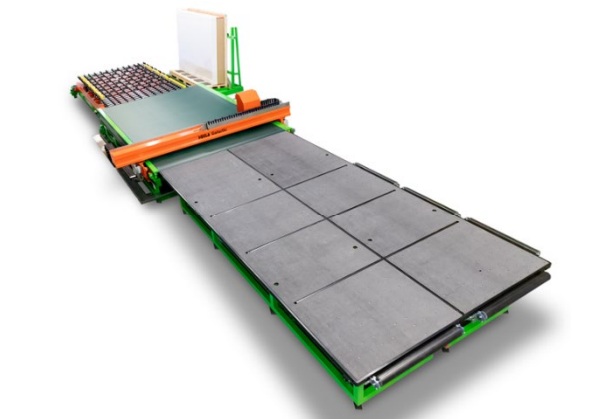
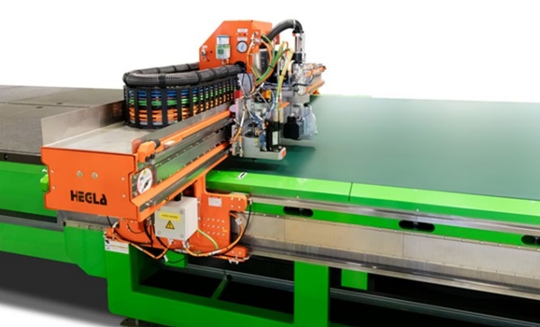
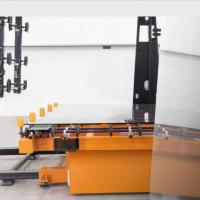
3.2. Ultra-thin glass cutting
A continuous conveyor belt as a full-surface base for the ultra-thin glass replaces the typical base on the cutting system and provides a firm, even, and non-slip hold. Sensors detect the position of the panes, eliminating the need to align the panes. The special cutting head cuts glass exactly according to the cutting plan. In the combination version with an additional cutting head for conventional float, processing up to 12 mm thickness is possible.
To achieve a high edge strength all moving components, including the cutting wheel, are designed for maximum precision, accuracy, and smooth running. Cutting errors and micro-cracks could otherwise lead to glass breakage. Here, HEGLA builds on more than 30 years of experience in cutting technical glass.
Due to the variance in glass dimensions in particular, the system operator is responsible for dividing the scored glass into individual panes and feeding them into the subsequent, fully automated process steps. Air cushion tables are more appropriate.
For the subsequent process steps, the individual panes are brought back into an almost vertical position using automated systems.
3.3. Glass handling and buffer storage from cutting to insulating glass line
The overall aim is to maintain the excellent edge strength after cutting into individual panes, as damage to the glass edges can have a significant impact on yield, just as with conventional thicker insulating glass.
Special technical measures must be taken between the glass cutting system and the insulating glass line for handling, transportation, and interim storage in order to prevent damage to the glass edges. In particular, this requires that the glass edges are supported as long, evenly, and sufficiently flexible as possible on suitable surfaces, and that relative movements between the glass and the supports are avoided during transport.
Taking these framework conditions into account, HEGLA has adapted their system technology between the cutting system and the insulating glass line to special thin glass requirements that both a fully automatic connection to the insulating glass production line, including intermediate storage, and a connection via special trolleys in combination with intermediate storage are possible. Conventional glass can be combined with thin glass in all variants in order to feed the special Glaston insulating glass lines.
4. Overcoming production challenges: IGU manufacturing equipment
The development of new triple IG units with ultra-thin glass require advanced technical solutions.
A novel production technology developed and patented by Glaston applies spacers to the thicker outer panes first. This approach modifies the process completely, minimizing stress on the ultra-thin centre pane and reducing the risk of breakage. The method allows for automatic production of new triple IG units with ultra-thin glass centre panes.
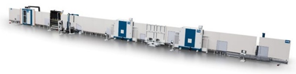
TPS technology plays a crucial role in the production. By ensuring exceptionally high insulation values and gas tightness, it measurably enhances the performance of these units. Plus, the completely automated system reduces the need for manual handling.
A cost-effective alternative to vacuum glass
Offering the same or superior performance at a lower cost, today’s new triple IG units with ultra-thin glass present a viable alternative to vacuum glass – another trending but costly glazing option. An IGU line for ultra-thin glass has a significantly higher throughput than an VIG manufacturing line, and can also manufacture double glazing.
5. Conclusions
Comprehensive solutions are now available in architectural insulated glazing unit (IGU) manufacturing to handle 0.5 mm and 0.7 mm thin glass up to 3200 mm x 2246 mm in size. This means that automated manufacturing lines capable to unload, handle, cut, sort, wash, laminate, and manufacture IGUs at a throughput of about 0.4 to 0.6 million IGUs per line per year are available.
Examples of equipment have been introduced in this paper. More details and information can be obtained by contacting the authors.
References
Ono, T, and Tanaka, K. (1999). Theoretical and quantitative evaluation of the cuttability of AMLCD glass substrates using a four-point-bending test. Journal of the Society for Information Display, 7(3), 207-212. https://doi.org/10.1889/1.1984477