First presented at GPD 2017
Abstract
Today’s parametric design tools allow for geometric variation throughout architectural projects, permitting the designer to manipulate i.e. an entire façade while controlling each element individually. The technical implementation of parametrically developed constructions is generally complex and demanding.
Architects, engineers and fabricators are confronted with challenges of geometry, structural design, complicated detailing and varying software interfaces during design and production. With the Parametric System these problems have been addressed by developing a tested aluminium façade system based on a set of variable geometries that are parametrically adaptable and supported by a secure, dedicated digital process chain as well as embedded structural analyses and the mass customization of certain components.
1 Introduction
For over two decades and following a century of efficient, functional and often orthogonal architecture, we are experiencing the extensive search for ever more complex building geometries and expressive architectural forms. This development is shaped by a wide variety of motives which, from our point of view, could hardly be more different. In some projects it appears important to architects and clients to set themselves apart from the “formal” standard.
At the same time designers declare solar radiation, shading and optimum lighting of the rooms to be “design parameters” and thus shape both the building form and the building envelope. Example projects, such as the C10 high-rise of Darmstadt University of Applied Sciences (German Façade Prize 2013 [1]) by Staab Architects and the Oxford Street Project in London by Future Systems show prismatic façades despite a different approach in the design process.
If the objective in Darmstadt was clearly the fusion of design with solar shading functionality, then the project by Future Systems shines in its optical brilliance and inimitability. Both however are still shaped by the rhythmical repetition of the same units. If you were to implement such strategies on free-form architecture, there would be an almost infinite number of different unit geometries.
Façade technology today therefore faces key challenges:
- Curtain-wall technology, now over 100 years old, is not a system that offers a strategic solution here. The classic glass curtain wall was developed against the backdrop of serial production for flat surfaces and is based on the addition of industrial, identical, mainly rightangled modules.
- Due to the progress and dissemination of modern parametric 3D planning tools in connection with Building Information Modelling (BIM), the aforementioned design strategies can be represented visually and geometrically, and in many respects successfully. However, this means that the standard market components must be forced into the desired form, which often makes each individual component a prototype.
1.1 Systematic approach
The desire for “free forms” requires “free construction products” in the sense of systems that can be manipulated parametrically. The fact that expensive individual solutions had to be used to implement nearly all the existing free-form designs of recent years is counterproductive and at odds with the creative will of the architects.
To resolve this, SCHÜCO and FAT LAB began a joint research project entitled “Parametric Concept” in 2012, the objective of which was to develop a façade system to enable geometric freedom in both the individual façade unit and the entire system. The constructive structural processing during prototyping and product development was carried out by ENGELSMANN PETERS engineering.
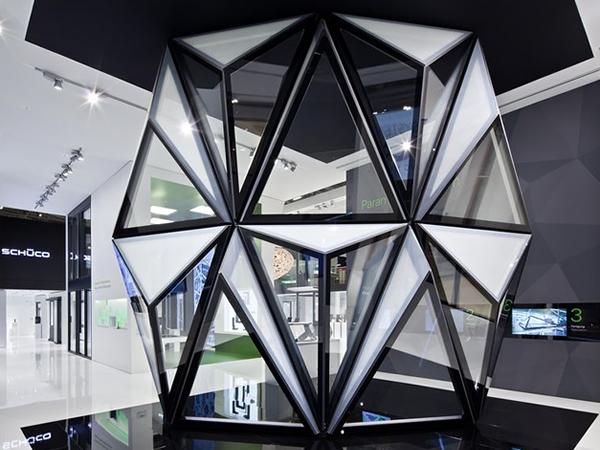
After the initial prototypes for BAU 2013 trade fair in Munich, the PARAMETRIC SYSTEM could be presented to visitors at BAU 2015 (Fig. 1). The systems concept is applicable and has a regulatory function. However, thanks to the large number of possible combinations and geometric manipulations, the formal design variations are almost limitless. A distinction must be drawn at façade level between local and global manipulation:
Local manipulation can be understood as the geometric differentiation of the individual façade unit. In this way, for example, deliberately turning transparent surfaces away from the sun can considerably reduce solar heat gain. Conversely, the generation of energy can be improved by the targeted alignment of PV surfaces. Key here is that a SINGLE repetitive geometry is not the aim; instead, EVERY unit can be designed in accordance with its position and function.
We refer to the application on building structures which are not right-angled and extruded as global manipulation. Through the coupling of units, covering double fold surfaces with rhombic or diamond-shaped units becomes possible. The unit connectors take on the task of “flexible” joints.

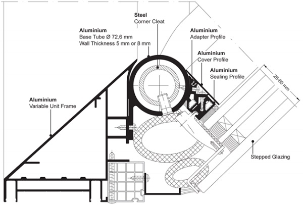
The choice of profile geometry is an essential element of the system concept which is understood as a strategy for the solution of a diverse range of tasks. The round tube geometry joined by using customized, inserted and therefore invisible corner cleats is the basis of the “Parametric System”.
The selected geometries and intersections of individual transparent, translucent or opaque surfaces permit the angle within each individual unit to be determined almost completely at will. The infill units are bonded to an aluminium frame and installed onto an internal secondary adapter frame, creating the thermal seal of the building as a structural glazing façade.
The cutting-edge Parametric System exhibit for BAU 2015 plays with the overall and individual unit geometries as well as unit depths. The local distinction between transparent and translucent glass units as well as the global flection of the entire surface suggest the future possibilities for façade design.
2 Structure
There are two notable innovations concerning the load-bearing structure of the façade:
-the parametric optimisation of the loadbearing structure
-the bonding of the insulating glass.
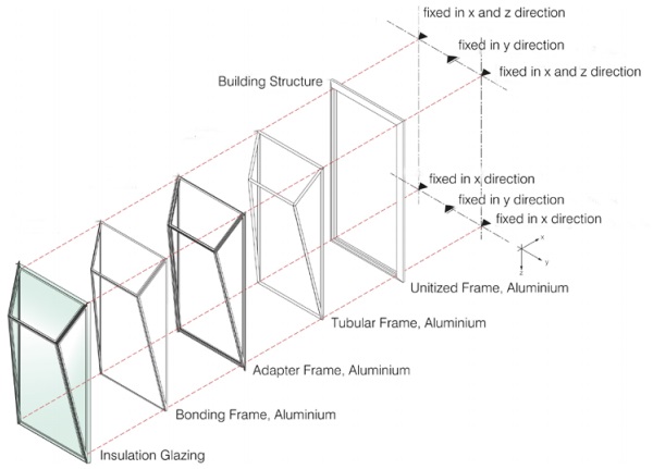
The modules of the Parametric System consist of a load-bearing aluminium unit frame which is fixed to the building structure at selective points and connects the modules structurally. Atop the unit frame is an aluminium tubular frame which, within the bounds of the module dimensions, geometrically defines and bears a three-dimensional, folded surface consisting of several panes of i.e. insulating glass (Fig. 2).
To achieve structural rigidity, the aluminium tubes are connected using welded steel nodes (corner cleats) with multiple arms. The node arms are inserted into the aluminium tubes with a plastic adapter, form-fitted with metal adhesive and are force-fitted securely.
Panes of insulating glass securely connect the fields of the three-dimensional frames constructed in this way. These panes of insulating glazing can be attached to the tubular frame using screws thanks to an adapter profile on the tubes and a frame bonded to the glass with two-component silicone. The panes are blocked to bear the dead load (Fig. 3).
3 Digital process
The design and implementation of geometrically complex façade systems generally requires improved coordination and planning by everyone involved. Coordinated interfaces in the process chain are essential to ensuring the continuity of the geometries and reference points [2] [3].
The faultless transfer of model information from one planning stage or software tool to the next has to be ensured. The repeated checking, adjusting and creation of drawings would otherwise drastically increase the time required for design. Ultimately, and of no lesser importance, the implementation requires highly detailed and robust information to ensure the precise machining, reliable creation and subsequent installation of the components [4].
The Schüco Parametric System offers diverse ways to design façades geometrically. To ensure the simple, reliable and fast design and implementation of this potential diversity, in addition to the profile system, a continuous, closed software process has been developed from the first design stages through to fabrication.
The use of a façade system rather than an individual solution is of benefit here as system rules and components can be used as a basis on which to build. Individual planning steps can thus be supported, automated and the complexity of the design process reduced through dedicated software components. The depth of information is adjusted in accordance to the planning stage in a Building Information Modelling (BIM) process.
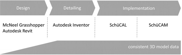
3.1 Design phase
Two plug-ins are available for the design and form finding process which can be embedded into the Grasshopper [5] and Revit [6] CAD environments respectively. A library of intelligent base modules with intrinsic system conditions thus facilitates the draft design and negates the necessity to know the rules underlying the system. The modules can undergo additional parametric modelling through the use of further external software components.
Developers therefore have diverse ways to generate and optimise shapes at their disposal. A systematic plausibility check inside the plug-ins ensures feasibility, whilst departing from the limits of the system remains possible. Special constructions beyond the system limits can therefore also be generated and subsequently implemented as a project solution. The models are simplified at this first level of design and do not contain all of the system components to prevent slowing the design process.
3.2 Detailing
The planning process is automated through the creation of detailed parametric detail models of the basic modules. The entire structure required are added to the designed geometries upon import into the Autodesk Inventor [7] software. An internal rule set forms the basis for generating the system and special components required, as well as their dimensions, processing and position. The plausibility of the models is tested again at this stage. Editing the detailed models, so that alterations and adjustments are ensured, remains possible.
3.3 Fabrication
The detailed model allows components and system profiles to be ordered directly via SchüCal, the manufacturer’s preparation and ordering software. The contractors do not have to carry out own planning work to the base system. This is particularly significant in reference to the required stepped glazing (Fig. 4) and the system nodes (Fig. 5).

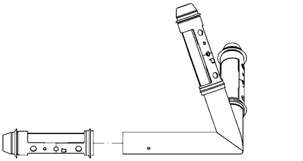
Latter are manufactured as system articles on the basis of the geometry transferred while ordering in a mass-customisation process. When generating the detailed model they are also clearly marked to ensure their correct assignment and position in the units. The data for the precise computer-aided manufacturing is also stored here and allows the machining to be performed directly on a 5-axis processing centre, i.e. the Schüco DC500 or AF500.
Throughout the continuous software process, all the data constantly remains in a single geometric model (Fig. 6), which everyone involved in the project phase can access at the required level. Here, the possibilities for parameterisation are not only used in the first design phase but also in particular during detailing. Compared to conventional design, the process of implementation is therefore accelerated considerably and system reliability is also the idea behind the software process.
4 Optimisation of structural system
The fundamental challenge in the development and in particular the optimisation of material use of the load-bearing structure lies in the geometric freedom of the system. With 11 different static module geometry types as the starting point, an almost infinite number of geometric variations can be created through the flexible variation of the internal tubular frame nodes in the X, Y and Z axes.
This naturally raises the question concerning which of the geometries is the least favourable in respect of the loads on the bars, nodes and connectors and which of the geometries should be used for the dimensioning of the components. The effects on the load-bearing structure of the façade include dead, wind, snow and temperature loads as well as live loads if the bottom of a structure is angled outwards.
An approximate approach or a simplified estimate will not suffice here to ensure a structure that is really costefficient. A parametric model was therefore created and used for the structural design. This makes it possible to create any number of geometric variations to cover all areas of application.
All these variations are then calculated automatically for the significant load combinations and pre-dimensioned via a programmed interface to a finite-element program. This makes it possible to precisely define geometric areas of application depending on the cross section dimensions sought and material strengths as well as to subsequently store them in a configuration tool.
The safety concept of the Parametric System envisages calculating the load-bearing capacity of the tubular frame. The stiffening effect of the bonded panes of insulating glass is initially not taken into account in the proof of the ultimate limit state. In contrast, the stiffening effect of the bonded panes of glass is taken into consideration for the serviceability limit state.
The interaction between the effects of the supporting structure and the panes is recorded using a highly detailed finite-element model, taking into account the stiffness of the bonding joints, which ultimately also allows the load on the bonded joints to be recorded. On the basis of such calculated estimates and accompanying tests, the number of areas of application of load-bearing silicone bonds has increased dramatically over the past few years.
Overhead glazing could therefore be supported and fixed exclusively using a bonded joint for the exhibit at the BAU 2015 trade fair on the basis of a precisely specified testing and monitoring concept. The lack of any retaining system for the glazing was granted individual case-specific approval.
5 Conclusion
Modern digital planning and fabrication technologies open new paths for architectural expression, though also require the planning process and construction methods to be rethought. In conjunction with the possibilities for reliably simulating and parametrically depicting complex relations, these new technologies provide important stimuli for overcoming the challenges of our time.
The digital revolution certainly has the potential to help facilitate another evolutionary leap in construction comparable to the development away from solid structures and towards skeleton structures, which not only defined a new construction method but also fundamentally altered and shaped the architecture of the last century.
Elementary research projects require close cooperation and a willingness to re-think existing approaches. This ensures constant technological development through innovative products and processes. The authors view the great interest and positive responses at BAU 2013 and BAU 2015 as the vindication of their endeavours to develop innovative solutions to future challenges.
6 References
[1] FVHF, “Deutscher Fassadenpreis 2013 für vorgehängte hinterlüftete Fassaden (VHF)”, Berlin, 2013.
[2] Azhar, S., “Building Information Modeling (BIM): Trends, Benefits, Risks, and Challenges for the AEC Industry”, Leadership Manage. Eng., vol. 11, no. 3, p. 241–252, 2011.
[3] K. Vollmers, Twist&Build creating non-orthogonal architecture, 010 Publishers, 2001.
[4] B. Kolarevic, “Architecture in the Digital Age – Design and Manufacturing.,” Oxford, Taylor & Francis, 2003.
[5] “Grasshopper 3D v1.0,” Robert McNeel &Associates, 2014.
[6] “Revit 2015,” Autodesk, 2014.
[7] “Inventor 2015,” Autodesk, 2014.