First presented at GPD 2017
Structural Silicone Glazing (SSG) is a curtain walling method that utilizes silicone sealants to adhere glass, ceramic, metal or composite panels to supporting framing members by means of a peripheral adhesive joint. In SSG curtain walls, silicone sealants serve not only as a weather seal, but also act as a structural bonding element, eliminating the need for exterior retainers and covers.
The paper discusses some essential findings of two recent research studies on the durability and service life of structural silicone glazing sealants and structures. The first study demonstrates, that specimens of a first generation 2-part silicone sealant taken from a SSG façade after 23+2 years of real life successfully passed the European ETAG002-1 performance criteria for residual strength.
In a second study, a new performance-based durability test method was developed in partnership with the Federal Institute for Materials Research Berlin/Germany (BAM). This method is based on simultaneously exposing system test specimens to artificial weathering and complex, multiaxial mechanical loadings. 2-part structural silicone sealants of the first and of the second generation where subjected to this test, which is considered to correspond to an anticipated service life of 50 years.
Introduction: Brief History of Structural Silicone Glazing
The SSG concept was developed in the USA during the mid-1960s. In the initial ‘all-glass system’, thick glass fins (mullions) were installed at regular intervals perpendicular to the face of the façade, then vision glass was adhered to these reinforcing elements using a transparent silicone sealant. The first building to use this type of glazing was constructed in 1964/65.
As time continued, further systems were developed in which the glass fins between the glass panes were replaced by aluminum mullions located behind the panes. Two different designs emerged, referred to as ‘two-sided’ or ‘four-sided’ SSG, where the silicone sealant served as a structural adhesive between the glass and the supporting structure either on any two opposite or on all four edges of the glazing panel.
By 1968, architects started designing seemingly uninterrupted, free-flowing strips of two-sided SSG. The two-sided SSG method became extremely popular and even today represents a widely used technique. By 1971, the first four-sided SSG curtain wall was installed on-site.
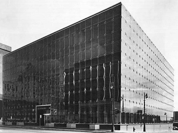
On this project in Detroit (Fig. 1), the structural silicone sealant transferred all loads from the glazing panels to the supporting structure; however, cast-aluminum spiders were installed as supplementary safety retainers at the intersections of the aluminum framing members to prevent glass panes from falling in the event of a structural seal failure. Having performed successfully for more than 45 years, this building now has become famous as the ‘granddaddy’ of the industry.

The first four-sided SSG project without a safety retention mechanism, the Chicago Art Institute, was completed in 1974. By 1978, this glazing technique began to spread more widely. Structural silicone sealants enabled the design of four-sided curtain walls with a completely flush appearance, resulting in smoother rain runoff, shedding of dirt, and easier cleaning. A real boom in the application of the four-sided glazing technique began towards the middle of the 1980s, when some ten years of experience had been gained with this system.
Benefits of Structural Silicone Glazing
During the 1980s, the SSG curtain walling concept spread rapidly around the world, as this glazing method allowed architects new levels of design freedom and offered a unique aesthetic appearance. Today, SSG has been become a resounding success with literally tens of thousands of projects demonstrating the aesthetic and performance benefits associated with this curtain wall technique. Nowadays, structural glazing is carried out almost exclusively using factory-produced (shop-glazed) unitized modules resulting in efficient fabrication, enhanced overall quality, increased speed of installation, and reduced on-site labor.
The Challenge: Estimating the Technical Useable Life of SSG Curtain Walls
One major concern with adhesively assembled structures in general is the long-term integrity of the structural bond. Therefore and because of missing comprehensive verification methods, with the aim of ensuring public health and safety, building code authorities in countries like Germany, France or Austria still require additional mechanical fasteners for four-sided SSG curtain walls to provide safe retention of the infill panel in case of structural sealant failure.
Today there is a significant number of SSG curtain walls globally that have now reached 30+ years of service. Building owners and code authorities are faced with the task of estimating the residual service life of these structures. Ultimately, the underlying questions are, what is the technical usable life of a SSG curtain wall – is it 50, 75 or even 100 years and how exactly will a structural silicone sealant degrade and ultimately fail? In some countries, this uncertainty is responsible for inhibiting the wider use of the four-sided structural bonding technology.
Therefore, important issues that remain to be addressed are the investigation of the regular functional behavior under superimposed loading, the prediction of the degradation behavior and the resulting long-term durability of adhesivebonded structures. The essential challenge that researchers face today is twofold:
a) How to develop durability test methods that provide a better representation of the actual service environment in the laboratory?
b) And, how to calibrate laboratory durability test results against actual in-service performance of SSG adhesive joints?
Besides the potential of a more realistic investigation of the interaction of choosen design and material combinations the ultimate objective, then, is a more realistic prediction of the technical usable life of SSG curtain walls. Two recent studies constitute major steps forward in this direction and, for the first time ever, provide compelling scientific support for service life estimates of SSG structures significantly in excess of 25 years. The findings validate anecdotal evidence gathered from successful field-performance of SSG buildings that have now been in operation for more than 30 years [2].
A Unique Opportunity: Calibrating ETAG002 Test Requirements Against Actual In-Service Performance
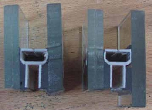
In 1985, the southwest facing bow front façade section of a building at IFT Rosenheim (Institut für Fenstertechnik e.V.), an internationally renowned authority in the testing of windows and façades, was installed using the then-novel ‘hybrid’ four-sided SSG system with glass sizes up to 1m x 3.2m (width x height). In this SSG design, special toggles engage in U-shaped glass edge spacers located at the periphery of insulating glass units.
Rotating the toggles by 90° during installation of the insulating glass unit mechanically secures the inboard pane to the support structure. Regardless of their mechanical fixation to the substructure, toggle-glazed hybrid SSG designs still expose the insulating glass edge seal to structural loads; therefore, an approved structural silicone sealant must be used to adhesively bond the U-shaped retention channel to the adjacent glass panes. The three-story high toggle-glazed hybrid SSG system broke new ground, as it was installed (in regards to the outboard glass panes) without additional safety retainers and without dead load support for the outer glass.

Such a hybrid SSG design corresponds to Type IV Glazing listed in ETAG002, as the structural bond transfers not just dynamic external loads, such as wind load, but also the self-weight of the infill panel. However, different from the situation in a regular (non-hybrid) SSG design, the structural bond in a hybrid SSG system is also subjected to climatic loads, as changes in temperature, atmospheric pressure, and altitude influence the sealed gas volume trapped within the insulating glass unit.
When the façade was refurbished for improved energy efficiency after 23 years of service, the dissembled SSG structure offered the opportunity of ‘calibrating’ the requirements stated in the European approval guideline for SSG sealants and systems, ETAG002-1, which was developed by the European Organization for Technical Approvals (EOTA) in 1991 [3-5].
Its comprehensive range of tests and stringent assessment criteria makes ETAG002-1 a very demanding standard for SSG sealants. The standard defines key provisions for bonding strength and durability of bonding strength of the SSG sealant and, notably, mentions that the provisions made in the ETAG002-1 are based on an assumed service life of the SSG structure of 25 years.
In 2012, after the dismantled façade had been stored in an unheated warehouse for 2 years, an experimental and statistical evaluation of the natural aging behavior of the structural silicone sealant installed at the IFT Rosenheim façade in light of the ETAG 002-1 requirements was conducted by a B.Sc. study at the University of Regensburg [6]. In order to do so, a total of 200 test specimens were cut from the hybrid SSG units utilizing a water jetting process. The study was supported by the IFT Rosenheim institute, a fact that allowed to compare the results with the previously collected reference data.
During its more than 23 years of service, the south- and southwest-facing SSG façade section had been exposed to harsh climatic conditions, with severe wind-driven rain exposure, high radiation heat gain (during days) and loss (during nights), and frequent freeze-thaw cycles.
Over the period of 2004 to 2011, air temperatures of - 23.7 °C and +35.2 °C were recorded as seasonal extremes. Thermocouples, installed within the SSG curtain wall in the vicinity of the structural sealant, recorded extremes of -9.0 °C (corresponding to –23.1 °C outside air temperature) and +59 °C (at an outside air temperature 32.5 °C) during a 12-month period starting in December 1985. The façade also received high levels of solar radiant energy; based on historical meteorological data for the period from 2004 to 2011, the average annual global solar radiation exposure at the city of Rosenheim is 1100 kWh/m2.
A key consideration for determining Safety in Use and, thus, the suitability of a SSG sealant according to ETAG002, is the stability of cohesive and adhesive properties when exposed to different environmental and aging conditions. Therefore, an important question to ask is whether or not the structural sealant that had undergone 23+2 years of environmental exposure would still pass the requirements of ‘Initial Mechanical Strength’ and ‘Residual Strength’ (now applied to natural aging) as laid out in ETAG002-1 sections 6.1.4.1. and 6.1.4.2.
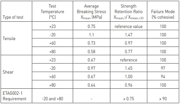
The aim of the Initial Mechanical Strength tests is to evaluate the bonding strength of the structural sealant when subjected to tensile or shear forces acting on the joint at different temperatures. Temperature-induced variations in the sealant’s properties may lead to a drop in mechanical and bonding strengths. Therefore, ETAG 002-1 stipulates that the mean tensile and shear strength values measured at -20 °C and +80 °C must not drop below a minimum of 75% of the corresponding values observed at +23 °C and that rupture must occur at an average cohesive failure mode of 90% or greater.
In the B.Sc. study, test specimens were subjected to destructive tensile and shear tests at -20 °C, +23 °C, +60 °C, and +80 °C. As can be seen in Table 1, across the board, the sealant passes both the above mentioned ETAG002-1 Initial Mechanical Strength requirements with flying colors.
The Residual Strength test is meant to determine the durability of the bonding strength. ETAG002-1 stipulates that the residual tensile strength after all types of accelerated aging tests must still equal or exceed 75% of the sealant’s initial strength measured at 23 °C and that the failure mode after aging must be ≥90% cohesive in nature.
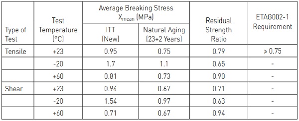
Table 2 displays the tensile and shear strength values observed in the Initial Type Testing (ITT) and on the naturally aged product along with the corresponding residual strength ratios for all test temperatures. Despite 23+2 years of natural aging, the sealant successfully passes the ETAG002-1 criteria. Such strong performance against key performance indicators at the end of the 25-year service life assumed by ETAG002 is quite reassuring. It may give conservative building code authorities the added confidence they need to consider future four-sided SSG structures without supplementary safety retainers.
The findings of this study are especially remarkable as the silicone sealant used in the IFT Rosenheim SSG application, Dow Corning Q3-3332 was commercialized as a first generation of neutral curing 2-part silicone long before the ETAG002 guideline was developed and failed to meet its stringent requirements, once this standard went into effect. The inability of this first generation 2-part silicone to meet the ETAG specification then triggered the development of Dow Corning 993, the 2nd generation, higher performance successor product, also neutral curing, which is capable of passing all SSG standards globally.
Back to Basics: Developing a Performance-Based Durability Assessment for SSG Sealants
Inspired also by the results of the field study mentioned above the need for a generalized, repeatable and time-accelerated durability test methodology comes again in the focus of interests. In 2012, the German Federal Institute for Materials Research and Testing (BAM), a leading research institute for science and technology in Germany, picked up the challenge of developing a performance-based durability test method for SSG sealants that better reflects the actual service environment and activates both the relevant performance features and its durability. The project was executed between 2012 and 2015 and accomplished the following major deliverables [7]:
a) Derivation of a realistic environmental and mechanical loading function suitable for accelerated durability testing;
b) Development of system test specimen that provide a better representation of the SSG joint;
c) Design and realisation of a test facility capable of simultaneously imposing weathering and complex, multiaxial mechanical loadings on the test specimen;
d) Evaluation of the durability of two ‘benchmark’ SSG sealants: 1st generation and 2nd generation.
The test was designed to reproduce typical environmental exposure and service conditions and is expandable with special load conditions like impacts or chemical loading. Consideration was given for the following loads [8,9]:
- Mechanical loads resulting from selfweight, temperature, wind and human impact loads;
- Climatic loads taking into account typical average and extreme temperatures, humidity, the number of rainy days and the average amount of precipitation and solar radiation per year;
- Chemical loads resulting from water (rain) or de-ionised water as solvent agent and cleaning agents (aqueous surfactant solution).
The deformation/stress loading was derived from parametric finite-element analyses (FEA) of a large-sized SSG glazing unit installed at a height of 50 meters on a building located in wind load zone II considering terrain categories II and III according to DIN 1055-4 [10]. The following assumptions were made in the parametric analyses:
- The SSG glazing module (2.5 m wide and 3.2 m high) is oriented vertically; the unit is structurally bonded on all four sides; the dimensions of the structural bond are 12 mm x 6 mm;
- The SSG system is glazed with either single pane, insulating glass, or stepped insulating glass (3 options) and installed either with or without support of its own self-weight (types II and type IV according to ETAG002);
- The design stress (σdes) of the structural sealant is 0.21 MPa.
Furthermore, in order to simulate a human impact on the SSG module, a separate FEA study was conducted to investigate the effect of a pendulum impact test according to DIN 18008-4 on the relevant sealant’s deformation/ stress loading. The multitude of FEA studies of single or multi-superimposed associated load cases allowed the BAM researchers to derive the maximum tensile and shear deformations occurring in the SSG sealant for each loading event. In general, they assumed the worstcase combination of loads (and resulting movements).
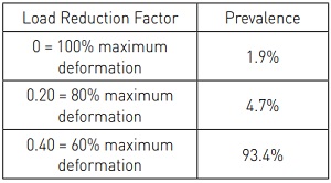
However, in order to derive deformation parameters for more regular load situations, they used the load distribution spectrum, as laid out in ETAG002-1 section 5.1.4.6.5 Mechanical Fatigue, as shown in Table 3.
The reduction factors represent the ratio of test deformation to maximum deformation. For instance, deformations corresponding to 80% of the maximum deformation only occurred with a prevalence of 4.7% in the overall deformation spectrum.
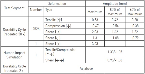
Utilizing the knowledge of the life-cycle load profile that was established during the previous research, the BAM researchers subjected the test specimens to repetitive durability cycles. Each durability cycle, which exposed test specimens for 24 hours to simultaneous climatic and multiaxial mechanical loads, was designed to represent one year of actual service exposure.
After the completion of 50 durability cycles, the test specimens were subjected to a rapid, complex deformation in order to evaluate the aged sealant’s ability to sustain an accidental human impact on glass. The impact simulation was then followed by another two durability cycles (see Table 4).
Simultaneously to the complex, twodimensional shear and tensile deformations, test specimens undergoing durability cycles were also exposed to temperatures of -10 °C to +60 °C, relative humidity ranging from 20% to 98%, rain events (intensified loading by use of distilled water) corresponding to 620 l/ m2 rain fall, and 1.4 MJ/m2 of UV light (290 to 410 nm) simulating relevant seasonal climate variations. In order to investigate the effect of mechanical fatigue, additional test specimens were kept separately in the BAM weathering chamber of the complex test facility that were subjected only to weathering without movement.
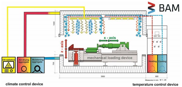
For the realization of the identified relevant annual service exposure on representative system test specimen and its repetitions for durability aspects a new complex test facility has to be developed. This unique test facility, see Figure 4, consists of the main constituents:
- mechanical loading device
- system test specimen fixture and bi-axial mechanical sensor
- climate control devices
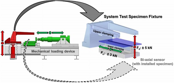
The mechanical key component of the test facility is a biaxial mechanical loading device, see Figure 4 and 5. With it loading in z-axis (extension/compression of the SSG specimen) as well as x-axis (alternating shear loading of the SSG-specimen) is realized with the help of a vertical and horizontal sliding carriage mechanically powered by independent working servohydraulic cylinders. New developed 2-D mechanical sensors monitor the mechanical response of the SSGspecimen to the superimposed loading. The SSG-specimen - a section of the glass façade element representing a representative bond situation - is fixed between the upper clamping of the vertical sliding carriage and the 2-D mechanical sensor as lower clamping, see Figure 5.
The assessment methodology of this new test methodology offers different ways for performance conclusions regards to functionality and especially durability. The methodology offers direct and indirect assessment opportunities by
a) discussion and assessment of the directly mechanical specimen response to loading by
- cycle-dependent continuity of the monitored course of mechanical characteristics supported by
- regular visual observation of surface characteristics and bond situation (adhesion; cohesion)
b) assessment of durability by comparative discussion of test characteristics relevant to ETAG002, section 5 “Methods of verification” before and after complex loading acc. to our superimposed load function
In terms of methodology validation as well as for traceability the project’s results to the actual technical guidelines both assessment ways were exercised on benchmark sealants representing the 1st generation and the 2nd generation of 2-part Structural Silicone sealants.
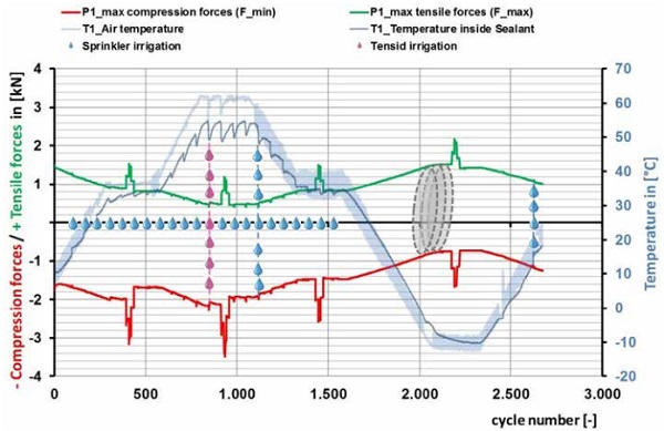
From the discussion of the swelling dynamically induced force paths (extension/ compression, shear) over all yearly seasons one can detect the general mechanical response of the sealants (e.g. detailed exploration of visco-elasticity), maximum stress states, temperature and humidity sensibility of the sealants and its mechanical consequences. With it also an individual system fingerprint is monitored.
From the path of the compression/tensile reaction forces of 2nd generation sealant in a determined specific SSG-construction (see figure 6) following consequences for the functionality can be concluded:
- actual distribution of the visco-elastic mechanical response, system stiffness by dynamic moduli, damping
- maximum and regular mechanical bond stresses to be adopted
- consequences from stress depending material softening (e.g. Mullin’s effect)
- specificity of thermal and hygroscopic sensibility (thermal elongation and/or thermoplasticity)
![Figure 7: Typical lifetime model for constructions and technical elements (acc. to [11])](/sites/default/files/inline-images/Fig7_37.jpg)
The typical service life time model for constructions and technical elements with 3 stadiums of deterioration [11] - adapted from the inflection points of a failure distribution (Hazard function) based on a bathtub curve - is presented in figure 7. The inflection point at the end of phase 2 represents the end of working life and the transition to the ultimate limit state.
According to the experiences in durability assessment so far (inter alia [11], [12]), this model represents our expectations in matters of the cycle depending course of mechanical characteristics.
For a performance-oriented life time assessment of SSG-constructions especially the bond behavior and its fatigue as well as ageing induced material changes are suitable criteria. Durability indicators (suitable mechanical characteristics) for the load depending deterioration may be detected especially from the course of system stiffness and its changes over repeated dynamic loading.
Resulting from simulated 50 years of use with the BAM-methodology the course of dynamic moduli of typical and corresponding SSG-constructions with sealants of 1st and 2nd generation are monitored in figure 8. In terms of comparative description the 2nd generation system exhibits a remarkable higher stiffness. The range of temperature dependent stiffness variation determines a similar temperature dependency of both investigated systems.
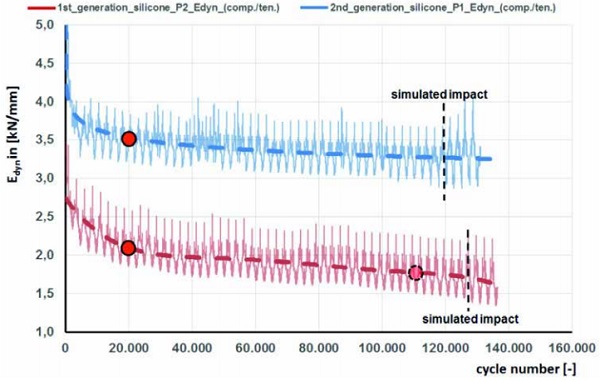
Because of their continuously course no complete failure can be deduced for both SSG-systems from the slope of the monitored system reaction graphs (here: stiffness modulus Edyn. defined by summarized force reaction related to the summarized compression and extension deformation load). At first glance, end of working life resp. beginning of phase III according to the life time model (figure 7) seems not yet attained.
Only the course of Edyn. for the 1st generation product gives indications for a changing negative function decrease at cycle numbers above 110.000 (suggested second inflection point) for higher stiffness reduction. Although both graphs show incipiently comparable mechanical behavior clear indication for different long-time behavior is indicated by the course of the Edyn. graphs from cycle numbers above ~20.000.
While the graph for the 2nd generation sealed SSG-system after a typically primary decrease with cycle numbers above 20.000 changes to constant slight decreasing the larger and growingly negative gradient for the 1st generation sealed SSG-system suggests higher sensibility under repeated loading. Additionally the course of Edyn. for 1st generation at cycle numbers above 110.000 (suggested second inflection point) gives indications for further and accelerated increase of stiffness reduction.
What is reason for the different durability of the investigated sealants resp. SSG-systems? Is the durability behavior of the 1st generation SG-system more dominated by mechanical effects (fatigue and/or deterioration of bond) or by ageing effects of the sealant’s material? Is there really an indication for generally affected system performance resp. is the end of working life reached?
An attempt for a more detailed system exploration is a separate discussion of the mechanical system reaction under extension loading (Edyn._extension) compared to the system reaction under compression loading (Edyn._compression). Background for this approach is the assumption both bond and fatigue sealant characteristics will be predominantely addressed by dynamically repeated constant tensile loading. Meanwhile aging caused system changes (changes in sealants analytical structure) should especially be reflected under swelling compression loads because of eliminated bond effects.
Although one can explore different ageing behavior of 1st generation silicone compared to 2nd generation silicone from the course of compression moduli (not figured in this paper) the growingly reduction of the 1st generation system stiffness (resistance) against repeated loading (see figure 8 and 9) seems to be obviously attributed to deteriorated bond by affected cohesion and/or adhesion. To clarify this hypothesis the course of stiffness under repeated tensile loading shall be discussed (figure 9).
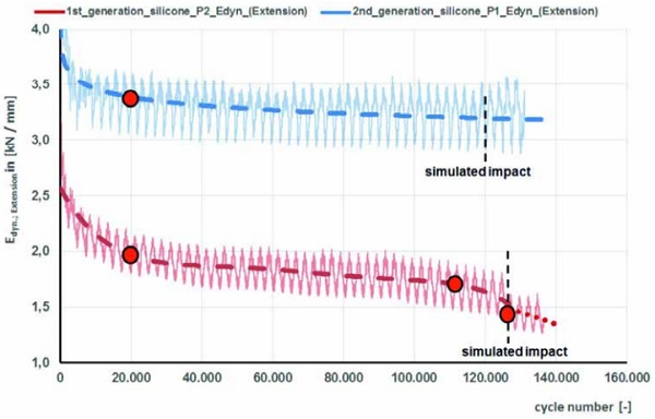
Consistent with the graphs in figure 8 and 9 the 2nd generation system doesn’t give indications for malfunctioning performance. Even after an extraordinary impact loading the further course of the stiffness under extension stays unaffected and stable. This mechanical system reaction under superimposed mechanical and climatic loading indicates performance according to the requirements. The end of working life is not yet attained.
In contrast the accelerated stiffness reduction for the 1st generation system already incipient in figure 8 at cycle numbers above 110.000 seems to be caused by affected bond. A clear stiffness reduction as indicator of the mechanical resistance is indicated at cycle numbers above 110.000. After impact simulation a further abrupt stiffness loss under repeated extension with rapid ongoing reduction is monitored. Even a load transmission is still given, an affected performance by bond malfunction is to be accepted.
Utilizing the advantages of the new assessment methodology we found validation for the deduced mechanical performance from accompanying visual observations. According to these results a performance and durability according to the requirements could be verified for the 2nd generation SSG system. Opposite to this performance the 1st generation system shows higher sensibility to ageing as well as bond loading resulting in lower durability under complex loading. Without total collapsing our validation methodology indicates that the end of working life was attained.
To utilize the methodology potential for direct traceability to ETAG002 requirements, the system test specimens were cut after completion of the durability test by waterjetting into standard-sized ETAG002-1 samples, which were then tested for their residual strength. Table 5 displays the results observed initially (prior to testing) and after completion of the durability test. Tensile and shear strength values along with the corresponding residual strength ratios (after aging) are shown. The data gathered at the completion of the durability test differentiate between test specimens that had undergone simultaneous weathering and enforced movement and those that were subjected only to weathering.
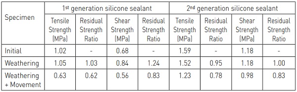
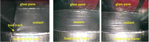
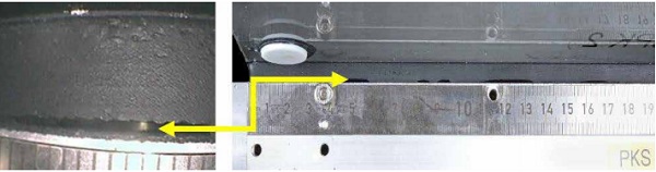
As can be seen, 2nd generation sealant passes the ETAG002-1 criterion for residual tensile strength, while 1st generation sealant fails this requirement for test specimens that had undergone simultaneous weathering and enforced movement. The differentiation between these two sealants becomes even more apparent when considering the extent of interfacial (adhesion) failure observed in the system test specimens. While the 2nd generation sealant showed only marginal loss of adhesion, primarily at the corners of the specimen, interfacial failure of the 1st generation sealant was more pronounced and, in certain areas, extended through the whole depth of the sealant (see figure 10 and figure 11).
Summary and Conclusions
Recently, two research studies focusing on the investigation of the durability and service life of SSG structures were completed. Both studies provide compelling scientific support for service life estimates significantly in excess of 25 years. The findings validate anecdotal evidence gathered from successful fieldperformance of SSG buildings that have now been in operation for more than 30 years.
The first study demonstrated that the 1st generation 2-part structural silicone test specimens obtained from a SSG façade after 23+2 years of natural aging successfully passed ETAG002-1 key performance criteria for initial mechanical strength and residual strength. This finding is especially remarkable as the silicone sealant used on this project was commercialized long before the ETAG002-1 guideline was developed and failed to meet its stringent requirements, once this standard went into effect.
In the second study, two benchmark sealants, the 1st and the 2nd generation of 2-part structural silicones, were tested according to a newly developed performance-based durability test method based on simultaneously exposing system test specimens to artificial weathering and complex, multiaxial mechanical loadings. The test results help to explore the mechanical behavior and sealants reaction under mechanical and superimposed climatic loading over an annual cycle.
The mechanical indicators are able to describe durability effects like ageing, fatigue and durable bond. It is a special advantage of the new methodology to complement the mechanical characterization by visual observations and traceability to the empirical ETAG002 requirements. After completion of this test, which is considered to correspond to an anticipated service life of 52 years, the todays structural 2-part silicone (2nd generation) still passed the ETAG002-1 criterion for residual tensile strength with only marginal loss of adhesion at the specimen corners; a result that demonstrates the outstanding bonding strength durability of this sealant.
Such strong performance against key ETAG002-1 performance indicators after natural and accelerated exposure is quite reassuring. It may give conservative building code authorities the added confidence they need to consider future four-sided SSG structures without supplementary safety retainers.
SSG has proven its reliability now for many years, which is a testament to the performance of the structural silicone sealants involved and the implementation of effective quality assurance procedures. Nevertheless further results of the BAM-research project (see e.g. table 5) proof the evidence for a performance-related working life assessment under superimposed mechanical and climatic loading opposite to separated specimen conditioning similar to ETAG 002.
References
[1] Klosowski, J.M. and Wolf, A.T., Sealants in Construction, Second Edition, CRC Press (2015), ISBN 9781574447170.
[2] Carbary, L.D., “A Review of the Durability and Performance of Silicone Structural Glazing Systems,” Glass Performance Days 2007, J. Vitkala (ed.), 190-193
[3] EOTA, ETAG 002 Structural Sealant Glazing Systems, Part 1: Supported and Unsupported Systems, European Organization for Technical Assessment, Brussels, Belgium (2012).
[4] Lieb, K., “It Keeps Lasting and Lasting and Lasting – Structural Glazing Façade Undergoes Duration Test” [“Sie hält und hält und hält… Structural Glazing Fassade im Dauertest”], Rosenheimer Fenstertage 2013, ift Rosenheim, pp. 49-53.
[5] Lieb, K. and Krewinkel, H., “23-Year Old Bonded Façade Undergoes Lab Testing – A Historical SG Façade is Subjected to Lab Testing After Actual Service and Displays Amazing Durability” [“23 Jahre alte geklebte Fassade im Labortest – Historische SG-Fassade kommt nach Realtest auf den Prüfstand und zeigt erstaunliche Haltbarkeit“], ift Rosenheim Publication
[6] Graf, N., Durability of Structural Sealant Glazing Systems (SSGS) – Material-based, experimental study and statistical evaluation of an ift facade subjected to natural aging in accordance with EOTA ETAG 002-1 [Beständigkeit von SSGS – Materialorientierte experimentelle Untersuchung und statistische Auswertung einer real gealterten ift-Fassade in Anlehnung an die EOTA ETAG 002-1], Bachelor dissertation, University of Applied Science Regensburg (2012).
[7] Anonymous, Structural Sealant Glazing – Evaluating the performance and durability of structural sealant glazing systems under combined mechanical and climatic loads.
[8] Kaatz, R. and Recknagel, C., “Advanced Evaluation of Structural Sealant Glazing Systems by a New System Test Approach”, ASTM STP 1583 (2015), DOI: 10.1520/STP158320140074.
[9] Recknagel, C. and Kaatz, R., “Exploration and Evaluation of the Performance and Durability of SSG Systems by Dynamic–Mechanical System Testing”, ASTM STP 1583 (2015), DOI: 10.1520/STP158320140064
[10] DIN 1055-4:2005-03, Action on structures – Part 4: Wind loads. Deutsches Institut für Normung e. V. (DIN), Beuth-Verlag, Berlin (2005)
[11] Ritter, F., „Lebensdauer von Bauteilen und Bauelementen“, Schriftenreihe der TU Darmstadt, Institut für Massivbau, Heft 22 (2011), 265 Seiten, ISBN 978-3-942886-00-0
[12] Ehrenstein, G.W.; „Hysteresis-Messverfahren – Verfahren der dynamischen Werkstoff- und Bauteilprüfung“; Schriftenreihe des Lehrstuhls für Kunststofftechnik der Universität ErlangenNürnberg; 273 Seiten; ISBN 3-9802740-4-7