This paper was first presented at GPD 2019 by Lenk P., Weber F. and Dodd G. from Arup London & Arup San Francisco.
Abstract
Structural engineers have gained considerable knowledge in the behaviour of structural glass from the pioneering and experimental beginnings to the advanced design of freestanding pavilions, structural envelopes and structures suspended from high rise buildings.
In this paper we will look at the potential of what is now a commonly used component in facade design - a load-bearing glass wall panel. We will review glass walls in the context of projects since 1998, influences and incremental steps they introduced to the understanding of the structural behaviour especially glass elements loaded in plane.
Stress concentrations at the loading points and methods of energy dissipation in the glass connections will be outlined. Analysis techniques to estimate buckling capacity and possible failure mechanisms will be briefly discussed together with installation tolerances and other challenges faced in the construction of the largest glass load-bearing wall structures.
1 Introduction
In the late 1980s, “structural glass” was monolithic toughened, predominantly with bolted connections. A system of monolithic glass fins and façade panels, bonded on site with structural silicone had been widely used in Asia and notable examples existed in the UK at the NatWest Tower in London and University of East Anglia Sainsbury Centre for Visual Arts, but it was no longer available in the UK because of concern over robustness.
Large glass walls were commonly suspended, which simplified the buckling problem of the fins to a local mode, with a conveniently simple analytic solution where the critical moment depended on the thickness. Laminated glass was not used in structural assemblies because workable bolted connections for laminated glass were not developed and the cast-in-place interlayers used to laminate toughened glass did not have sufficient tear resistance to make a laminated option any safer than monolithic toughened and heat soaked.
In 1998 during construction of Canada Place in London, Ron Arad was commissioned to design a sculptural skylight over the intersection of two underground shopping arcades. His concept was to support a tilted discus form of 13m diameter and 7 tonnes, on a 7.5m diameter cylinder of clear glass directly over a circular opening surrounded by a grassed area. The challenge was to support and hold down the discus and secure it to the concrete slab, which was expected to deflect and deform.
A new bending and toughening process had been offered in the UK, from an independent glass processor who had devised a skeleton sag mould trolley process to bend and temper thick glass. The cylinder of 12 curved panels composed of 2 x 15mm fully toughened panels with a cast resin interlayer could be bolted securely to the glass-fibre composite discuss, which was very stiff where the glass attached below a cylindrical stiffener almost 2m deep. The concrete structure was comparatively flexible and expected to deform, raising the question of how to keep the force distribution between bolts predictable.
To make the reaction through each bolt fully determinate, the 12 glass panels were each mounted by two bolts onto a steel balance bar, which was in turn balanced on another beam with the adjoining panel, and each pair of panels was finally balanced with another pair. The three teams of 4 panels were thereby attached to the slab at only 3 points and all 48 bolts (24 top and 24 bottom) carried predictable forces, whichever way the wind would blow and however much the slab might distort over time. This fixing system was complex but enabled the connections in the glass to be justified as simple bearings on one layer of glass, which were verified by tensile tests on double-ended glass specimens.
The sculpture, named Big Blue, was inaugurated in 2000 and survived, with a couple of glass replacements caused by impact damage to the glass, until it was removed in 2018 to allow more commercial use of the open space. The complexity of balancing forces between bolt connections had emerged as a significant barrier to using glass walls to support a roof, particularly when the roof was extremely stiff. It was clear that it would preferable to distribute forces though a plastic or elastic element and for the roof to be more flexible than the foundation. It would also be preferable to avoid net uplift on the glass panels, so that the edges could work in bearing and bolts could be avoided.
Eric Parry Architects designed a renewal of St Martin-in-the-Fields church at the side of Trafalgar Square in London, including a glass pavilion to enter the crypt, which opened in 2008. Early concepts for the crypt entrance involved stacked glass cut into a figure-of-eight profile, supporting a domed roof, but the cost proved to be prohibitive. The alternative was to build the walls of tall curved glass in 10 panels, 8 of which would support the roof and provide lateral stability. The only non-glass components to reach the roof were two small internal rainwater downpipes.
The 8-tonne weight of the stainless-steel roof with a central skylight was sufficient to overcome wind uplift but the 4.6m edges of the tall curved panels, 2.2m wide, had to be checked for stability under the combination of dead load and wind force. One layer of 10mm and two layers of 12mm thick annealed glass were chosen to minimise the effect of vandalism and to maximise postbreakage robustness because the location is public and very busy. At this scale, it was clear that manufacturing tolerance, wind load deflection, interlayer properties and the combination of vertical and shear loading needed to be resolved in a non-linear model and the earlier simplified approach applied to Big Blue was no longer appropriate.
Manchester Central Library was refurbished and re-opened in 2014, including a glass entrance pavilion, designed by Simpson Haugh and Partners to link the library to the Town Hall. At a larger scale than St Martin-in-theFields, 7m tall and with a 30t roof, the curved heat treated laminated glass panels were not bolted down but supported on a patch of resin at mid length of the bottom and top edges and bonded into the bottom channels with silicone. Horizontal shear forces were primarily resisted by vertical shear in the silicone joints between panels. Door openings interrupted the sequence of wall panels but could not be used to provide stability. The manufacturing and construction sequence, and a planned method to replace and re-load any of the wall panels, were crucial parts of the engineering.
Foster & Partners’ concept for the entrance pavilion to an underground auditorium in USA involved a slim disc roof appearing to float in the landscape, supported on four columns. The 7m tall glass wall describing a large cylinder beneath the disc would need a structure to resist wind and seismic forces and the glazing system would need to accommodate seismic movement. The simplest construction would be to make the glass wall panels span vertically, using their thickness and curvature to resist bending due to wind load, and to support the roof, eliminating the columns.
The forces in the glass would then be determined largely by the seismic acceleration of the foundation and the mass of the roof. Any pavilion with minimal structure, and certainly no central core, would benefit from base isolation in a seismic zone, so this provision was established early in the project. The feasibility of using the glass panels to support the roof depended firstly on minimising the mass of the roof, for which fibre composites were a natural part of the concept, as was later demonstrated in comparison with an optimised steel scheme.
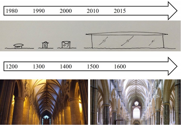
Secondly, on bonded connections to the panels to take holding down forces and “fuse” components to limit the maximum force that could be imposed on a connection, to achieve redistribution without a complex mechanical linkage. In past decades the sizes of glass structures increased but also knowledge in engineering and design of transparent structures defying gravity and providing natural light. It was a challenge that master builders tackled over centuries in design of medieval churches, where incremental steps seem to be critical in success, supported by wealthy patrons to drive design further. A common similarity between past and present designers.
2. Structural Behaviour
While all our calculations should be justifiable with first principles, back of the envelope calculations are essential in all conceptual work, structural glass projects are usually heavy in finite element analysis from very early stage. Glass structures are complimented with other materials as steel components, structural silicones, adhesives, visco-elastic interlayers adding further complexity in structural calculations.
Stability Considerations
Conservative but realistic imperfections are a fundamental input parameter in the stability analysis of any structure. Global bow amplitude, local distortions as well as shapes of those distortions were examined in [Belis et al 2011] where authors concluded that recommended characteristic value of uo/L is 0.0025 mm/mm (L/400) which is minor improvement from typical glass product specification of 0.003 mm/mm.
However, it shall be noted that such initial imperfection for a 10m long element will produce 25 mm out of plane distortion mid span which maybe visually disturbing or not meeting other performance criteria, likely to be outside of the tighter project specification.
Any additional lateral horizontal loads which may act on the glass panel shall be considered in conjunction to compression load and deformations of the glass panels added positively to the initial imperfections. In the situation of one-way spanning glass walls (bottom to top) without out of plane edge restrains, additional midspan deformations from normal wind pressures or horizontal seismic accelerations might be an order of magnitude higher. Usually considered deformation limits are L/100 for laminated glass walls to L/175 for DGU panels.
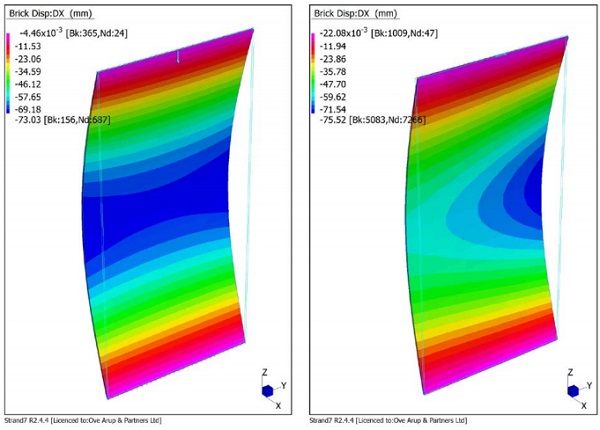
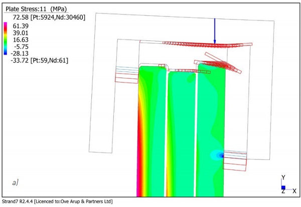
Two analysis models are presented on the figure 2a. On left hand side figure a simple Euler buckling with concentrated load in the middle was considered while on the right hand side picture in plane shear load on the top edge of the panel was considered. Both panels are vertically supported on two bottom points which are located 150mm from the edge, providing compression and tension support with stiffness of 100kN/mm. This arrangement is modelling typical bolted glass connection. Other structural systems based on adhesive connections were used previously in other schemes and are not investigated in this paper in detail. Further information can be found in [Coult, G.; Eckersley, B.; Lenk, P..2018].
Some additional assumptions when designing with structural glass walls are listed below:
- Roof should be capable to connect all glass panels together and act as a stiff diaphragm.
- Global stability could be provided by the glass panels being connected by structural silicone at the vertical joint
- Global stability could be provided with the panels being structurally silicone bonded to the base channels
- Effects of torsional load shall be carefully examined
- Effects of geometrical stiffness in curved glass elements can be positively considered
- In case of bolted glass, effects of bending stiffness of pins and rotational constrains in the glass hole shall be carefully examined and connections detailed to avoid stress concentrations.
- For bonded connections with wide silicone joints, effects of restricted curing behaviour and non-typical load behaviour needs to be assessed by analytical studies and testing.
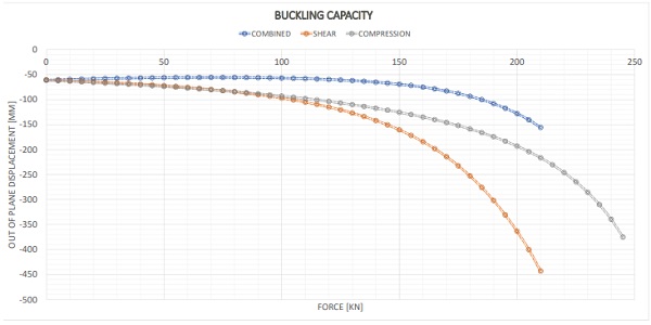
Graph 1 shows the relationship between applied load and maximum out of plane deformation of the 6m tall and 3m wide flat glass panel comprising from 3x12mm. Compression buckling, shear buckling and combination of both actions are presented. Good corelation between the finite elemnt calculations with maximum buckling force of 245kN to analytical first principle critical euler buckling force of Ncr= 223kN and structural glass eurocode approach based on buckling curve NbRd= 191kN was found.
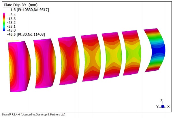
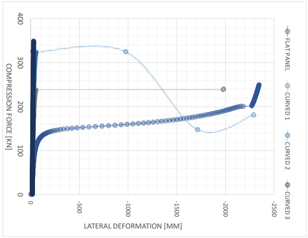
Curved glass is popular among architects and clients, therefore we carried out a comparative study to investigate effect of the curvature on the the buckling capacity of the glass panel. All panels are 6m tall and 3m wide supported on top and bottom only. Cylindrical curvature varied from 20m radius to the radius of 1.5m. Initial imperfections of 17mm H/350 were considered only. No additional out of plane deformantions were added in this study. Long term material properties of the interlayer were considered.
Results of above analysis are presented in figure 3, where glass out of plane deflections at 100kN compression force are presented on left and buckling curve for flat panel and panel with curvatere of 20m,15m 10m is presented on figure right. A predicted two fold increase of compressive buckling capacity was detected. This is predominantly due to the geometrical stiffness of the panel as well as distribution of imperfections and the influence of additional out of plane deformations on the curved panel. Further study considering effects of out of plane deformations was outside of the scope of this paper.
Load Introduction and Stress Concentrations at supports
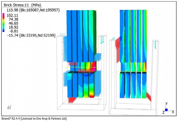
Both load introduction and support conditions will have significant impact on the global buckling capacity of the glass wall and on the capacity and robustness of the structural system. Initial local glass imperfections such as edge step and eccentricities in load distribution shall be considered in the verification calculations. They may reveal uneven stress distribution in the glass panels and local minor axis bending as presented on figure 4a. Load distribution in bolted glass was examined by many authors [Overend 2012]. Designers must consider effects of the bending stiffness distribution between steel pin and steel plate.
In figure 4b two structural models are presented where stiffness of the infill material differs significantly (silicone, epoxy resin). In the model on left, silicone is placed between glass and face plate while epoxy resin is forming a stiff substrate between pin and edge of the holes, while in model right the situation was reversed providing stiffer load path to the glass faces. The difference in load distribution confirmed engineering instinct and revealed stress concentrations.
Stiffness relationship
Substructure interaction is a critical aspect in the design and shall be always carefully well thought out. Spring systems can reduce differences in load and allow for substructure deformations, another possibility is to apply transfer beams which will distribute load equally and can arch over hard/soft spots. To avoid excessive rotations and panel clashing, rocker details are typically installed. Vertical movements in between panels will have to be resolved and structural silicone solutions may be unsuitable in such circumstance.
3. Detailing
Depending on space limitations, different detailing approaches are typically pursued for the head, base details as well as the panel joints.
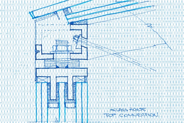
Head Details
The head detail provides the load introduction point for the roof and there is often a challenge to minimize the detail for aesthetic reasons. The detail typically features a longitudinal channel that is structurally bonded to introduce horizontal in-plane shear into the glass wall panels. Vertical forces from the roof are introduced through a patch of non-shrinking grout at the centre of the top glass edge. This reduces compression in the glass along the vertical glass edges. The connection design to the roof structure needs to consider that any rotation of the roof edge does not transfer into the glass shoe so that load eccentricities are minimised.
Base Details
The glazing base detail typically consists of a structurally bonded or bolted shoe with patches of grout near the glass panel corners to transfer vertical forces. The base often provides more space and is therefore used for the in-plane rotational restraint of the glass. Bolted connections or structurally bonded shoes that exceed the recommendations for structural silicone applications should be load tested to verify for uncertainties such as curing state of silicone because very deep joints can impede curing or cause joint tearing.
Innovative energy dissipation systems for seismic regions
In seismic regions, the lateral acceleration in a seismic event can quickly outweigh wind loads. It can become necessary to control lateral acceleration and provide mechanisms to prevent overloading of any glass detail. Structural silicone has a damping ratio in the region of 2%, therefore its ability to dissipate energy is limited. A typical way to control lateral acceleration is through base isolation. The isolators can be ‘tuned’ to absorb a certain amount of movement (width of the isolator) and to control the lateral force introduced to the isolated structure.
If the isolator meets its design displacement, however, a shock is introduced into the structure. To avoid the shock leading to a failure of the glass structure, a ‘fuse element’ can be provided at the connection of the glazing shoe, for example in the form of a steel connection that can yield. This innovation, which was part of the original concept design, was successfully used in a recently opened award-winning glass structure.
Panel joints
Vertical silicone joints may be employed to help with the buckling resistance of the glass wall panels, but with growing size of the panels, their influence was found to be relatively small and must not be over-estimated.
Services in panel joints
Glass walls provide little opportunity to run services into a ‘floating roof’ structure. The only place for services is the joints between the glazing panels. The authors successfully designed water pipes and electric conduits to supply sprinklers, lighting and other electronic services to fit into a series of 1” wide silicone joints.
4. Fabrication & Installation
Fabrication
Multi-layer glass build-ups require careful production to minimize visual distortion and haze effects. Visual distortions are particularly critical with curved units. The glass forming technique (cold bending lamination, roller bent, slumped chemically tempered) affect the cost for the glass as well as the visual quality. Full scale units should be reviewed under realistic viewing conditions and assessed for global (overall geometry, inconsistent bend, haze) and local (roller wave, edge dip) distortions. Review glass against a realistic backdrop (not against a wall in proximity) and at oblique angles, which are crucial with transparent curved walls. It is common practice to factory assemble glass and head and base connectors for best quality and monitoring of the production practices.
The roof structure should be assembled with the future load transfer points to the glass wall in mind. This might involve assembling the roof on top of a series of controlled bearing points, which coincide with the glass connection locations.
Installation
The installation method is crucial to guarantee even load distribution across the glass wall panels. The stiffness of the floor and roof structure may influence the load distribution and need to be considered in the installation sequence. The roof structure is either propped to the right level and the glazing panels installed underneath, or the glass wall is installed first, and the pre-assembled roof lifted on top. For both methods the critical part is to ensure even load distribution across all panels, for example though adjustable bearings or grouted connections. Any temporary shoring needs to be designed such that the roof or floor do not experience any deformations that change the force distribution in the structure after de-propping.
Monitoring of the Structural Behaviour
It is crucial to control loads into structural glass panels to guarantee that loads in the individual leaves and sheets are as per design intent. The installation sequence must therefore include methods to monitor and control the movements or forces in the structure during and after installation and for any future glass replacements. The design of the roof should therefore consider the location of monitoring points into the floor and soffit design. Structural calculations for the structure should be performed with the location of the monitoring points in mind, so that measurements can be associated with the predicted movements of the structure.
5. Conclusions
There was always a desire to support roofs from clear glass walls, and the engineering response has progressed from a starting point that robustness and damage tolerance are essential, mechanically balancing forces between mechanical fixings, through large increases of scale that required detailed consideration of buckling behaviour, the development of bonded connections to distribute large forces and fuse components to limit connection forces under extreme conditions. The production of large scale processed glass to very high standards, fibre composites construction and the availability of force monitoring technology have been key enabling technologies in making structural glass walls perform as gravity and stability elements.
6. References
[1] Belis, J., Mocibob,D, Luible A., Vandebroek, M, 2011, On the size and shape of initial out-of-plane curvature in structural glass components, Journal of Construction and Building Materials, 25, p.2700-2712, 2011,
[2] Coult, G.; Eckersley, B.; Lenk, P, 2018, Manchester Town Hall, a Case Study in Structural Glass Reliability and Robustness. In: Challenging Glass Conference Proceedings, v. 5, p. 457-468, May 2018. ISSN 2589-8019.
[3] Overend, M.: ‘The appraisal of structural glass assemblies’. PhD. thesis, University of Surrey, March 2002
[4] working draft of the CEN-TC250-SC11_prCENTSxxxx- Design of glass structures – Part 3 Design of in-plane loaded glass components and their mechanical joints