
Article Information
- Digital Object Identifier (DOI): 10.47982/cgc.8.426
- This article is part of the Challenging Glass Conference Proceedings, Volume 8, 2022, Belis, Bos & Louter (Eds.)
- Published by Challenging Glass, on behalf of the author(s), at Stichting OpenAccess Platforms
- This article is licensed under a Creative Commons Attribution 4.0 International License (CC BY 4.0)
- Copyright © 2022 with the author(s)
Authors:
- Michael Engelmann - Josef Gartner GmbH
- Klaus Reuschle - Josef Gartner - a division of Permasteelisa North America Corp.
- Salvatore Muscatello - Josef Gartner GmbH
- Thomas Sperandio - Josef Gartner GmbH
Abstract
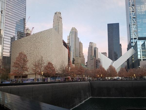
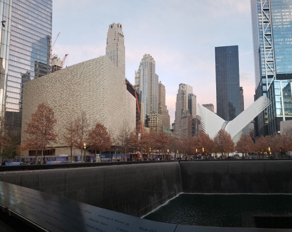
The new World Trade Center site was rebuilt after 9/11 comprising seven mayor skyscrapers around the memorial site and the 9/11 museum. Between WTC 2 and WTC 3, Santiago Calatrava’s Oculus Station spans its wings in the NY air while finally, the complex is completed by the “The Ronald O. Perelman Performing Arts Center”. This building sets a one-in-a-kind visual appearance to the area. Its four-sided, 42 m tall, even facade is made from 4736 equal-sized insulated glass panes. More specifically, the architectural vision is to create a marble stone front covered with glass which results in a stone-glass laminate as a part of an insulated glass unit.
The marble shows a distinguished white face with crisp black veining. Each of the four elevations of the building impresses with a perfect symmetry and veins touching at the vertical center line. So, the design team at Josef Gartner was challenged to set-up a logistics chain from quarry in Portugal where the stone panels were cut and catalogued to glass production of laminated glass in France and IGUs in Germany and assembly of curtain wall mega-panels at Gartner in Germany up to the site in Lower Manhattan. Our in-house logistics concept, customized for this project, guarantees that each individual piece of stone finds its correct and unique spot defined by the architect on the 7,000 m2 surface – a large-scale game of “Matching Pairs”.
The steel base building provides a cantilevering roof that holds 128 hot-rolled steel mullions. Each 36 m in length with one intermediate lateral support only. This allows the visitor to experience a clear and unobstructed view along the transom-free facade elements that carry the translucent stone-wall. During the day, it appears white from the outside and shines with an amber-glow during the night when the interior space is illuminated. We show the use of a novel stone-glass product that is exposed to a variety of requirements. The logistics chain is described from quarry to site making sure that the architectural and economical demand is met along the whole process. Finally, the team connects all branches in facade design using stone, aluminum, glass and architectural exposed structural steel assembled in one landmark project.
1. The Building
The story of the “The Ronald O. Perelman Performing Arts Center” goes back to the time after 9/11 when the City of New York developed plans to rebuilt the site. The multi-disciplinary art complex was considered the cultural core in the shadow of the new World Trade Center Towers and in the pr ominent neighborhood of the WTC memorial and Calatrava’s Oculus station. However, its planning did not go as smooth as expected as the final design by REX’s Joshua Prince-Ramus was chosen after turbulent discussion over an earlier design that was abandoned. The simple and pure form of the building contrasts Frank Gehry’s and Snøhetta’s prior design and lives in respect and coexistence with the surrounding area.
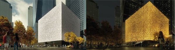
Right above the metro station, a steel cubical rises 42 m tall in the air presentingfour identical sides which are covered with 4736 insulated glass units made from striking glass-marble-glass composite. Their design and engineering was discussed earlier (Engelmann et al. 2021). The surface is translucent and shines in amber when back-lit and white with crisp black veins when exposed to sunlight. The visitor’s attention is attracted by the symmetrical composition with concentrated veins in the center and fading structure at the edges (Fig. 1).
The full facade is hanging from the roof that cantilevers 3 m from the base building and supports 128 vertical steel mullions 5 ft (1.5 m) apart. There are no transoms between the main facade mullions so the visitor gains a clear an unobstructed view of the marble texture.
What is the challenge when designing and engineering “just a cube”? An exceptional logistics was key as the stone underwent profound inspection and documentation near the quarry in Portugal. Photographs of each tile, both with natural light and back-light to expose the veining amount, directionand angle were uploaded to an in-house computer model assisting the architect in the selection process. So it was practically decided in the quarry at what position the stone was placed. This information needed to be carried along the full supply chain through production of laminated glass, curtain wall units and installation on site. As it is common in projects that include stone, a large amount of fragile plates shattered during the process and needed quick compensation. Therefore, a digitalworkflow was generated covered by an in-house software as described in the next section.
2. The Logistics
2.1. Steel
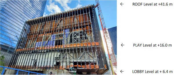
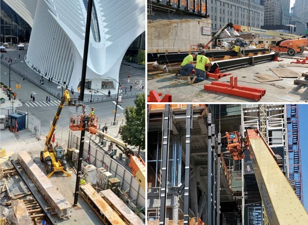
First things first – the base structure in this project was delimited by the edge of the ROOF and the floor slabs at PLAY and LOBBY level – 41.6 m, 16.0 m and 6.4 m above ground (Fig. 2). So an additional 700 metric tons of architectural exposed structural steel (AESS) were designed, engineered and produced in Gundelfingen, Germany to carry the full weight of the curtain wall.
The purist design demanded vertical mullions only without any intermediate transom to bridge the 5 ft (1.5 m) grid. Four corner mullions, 24 reinforced mullions (Fig. 3, left) and 100 hot rolled HEB 260 sections from S355 formed the base. To ship this amount of material, twelve 40 ft and 31 45 ft containers and three ro-ro flatrack containers were loaded. Each mullion was split in three segments and was packed along with matching splice plates and aluminum bracket hooks to connect the curtain wall units to the supporting structure. Their travel path guided them via road transport to the port in Hamburg, Germany, by ship to a warehouse in New Jersey and, finally, via just-in-time delivery to site at the World Trade Center in Downtown Manhattan.
2.2. Stone logistics
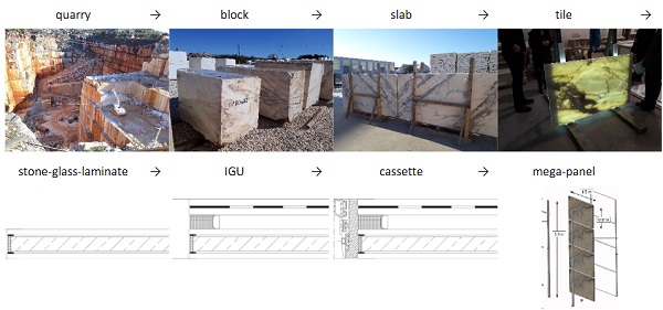
After careful planning of the steel works, the logistics for curtain wall unit production needed precise attention (Fig. 5). The supply chain started in a quarry in Portugal were 227 mega-blocks of Estremoz marble were cut and labelled according to the source bench in the quarry. The architect examined each block in person or via photo documentation to approve or reject the raw material for the project.
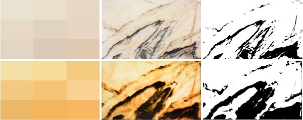
A stone saw sliced the mega-blocks into slabs that were still too large in area for use in the building. It was necessary to hone them first to the final thickness of 12 mm and to allow for determination of the best fit 5 ft (1.5 m) by 3 ft (0.9 m) rectangle on the surface. This was done manually with a wooden frame and, in parallel, digitally based on additional photos of the slabs. It must be noted that the choice of the best fit not only depended on the grade and angle of natural veining, but also on daylight and backlight shots from the stone scanner (Fig. 4).
Additionally, the background color and the veining percentage were quantified. The threshold luminance value for each pixel was summed up by weighting 30 % of the red, 59 % of the green and 11 % of the blue proportion in the RGB-color spectrum. A luminance smaller than 0.7 was considered black veining. Integrating over the full photo gave the veining ratio. From the image data assessment, front and back, top and bottom edge as well as a bookmatch indicator were proposed to prepare the positioning on the facade. The architect’s selectiongave the signal to start the production of 8585 tiles of stone.
2.3. Glass logistics
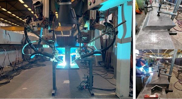
Approved stone tiles arrived in France for production of laminated glass. First job included the check of the product’s status upon arrival as a considerable number of slim tiles were subject to cracks or fragmentation. The second step comprised drying the natural material in an oven to remove all remaining moisture before lamination. This complex process was performed by the glass supplier who was running a steep learning curve before arriving at the most suitable, optimized drying procedure. It should be noted that porous marble is very susceptible to drag moisture from the ambient air. Therefore, the production process of the stone-glass laminate was under tight time constraints. The pre-laminated assembly was finished in a vacuumed bag. Additional runs of quality checks ensured that there was no delamination, visible cracks or enclosures of alien material.
In total, 5197 or 60 % of the raw stone tiles where used to fabricate a hybrid laminate from 5 mm heat-strengthened glass, 12 mm of stone and a second pane of 5 mm heat-strengthened glass. The assembly and their components were tested in four-point bending and during planar static air-pressure to find the most suitable and durable combination (Engelmann et al. 2021). Including all provisions 4896 (or 57 % of the cut tiles) were used to assemble curtain wall units. For potential replacement, 100 pieces of stone-glass laminates were produced. In case of damage, the project team decided to replace up to eight IGUs to keep the aesthetical bookmatch design
2.4. VDL process
The exchange of stone image data was organized virtually by programming an individual piece of software for a virtual dry layout (VDL) which supported the architect in the endeavor to compose the best fit between original design intention and revealed texture of natural stone from the quarry. The stone’s status was digitally changed after confirmed arrival at the IGU production plant. At this point, the final orientation could still be flipped and rotated as the production of the cavity on one side of the stone-glass laminate defined the inside and the outside of the unit. This provided the architect with the longest possible opportunity to be creative while maintaining a tight production and delivery process.
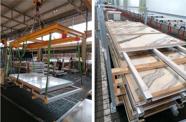
It was chosen to design one band of facade units at a time. This included all single facade units at one altitude and all four elevations of the building. Also, bookmatch along a horizontal line at mid-span between bottom and top edge of the elevation was intended, so a second band of units related to the first was added. So a total of 1024 IGUs (2x 32 x 4 elevations x 4 IGUs per unit) were approved by the design architect at once. This decision started the packing of the eight IGUs on one metal glass rack in the correct orientation and sequence for bonding them later onto one mega-panel.
Additionally, this started the logistic process of assigning four glass datasheets to a facade unit summarized in a unit data sheet. This information was tracked in the BIM software and aligned with production planning. The virtual model was materialized by printed datasheets which, in contrast to conventional facades, included a printout of the individual unit with its four stone textures for physical quality checks at the production line.
2.5. Units production
The gener al concept during unit production was split in two main steps:
- In production step 1, the IGU was placed face down on the production line and supplemented with a pre-produced aluminum framing with a 6 mm seam in between. At two positions along the bottom edge, blockings were placed to mark the position of the glass bearings and to keep the space clear of silicone that was placed between the glass and the frame. After rotating the glass, the outside groove was also filled. After curing of the silicone, the so called “cassette” was ready for further processing.
- Production step 2 comprised the production of mega-panels. To do this, two aluminum mullions were place on a rack at the intended distance and were equipped with glass bearings. After this step, the cassettes were positioned exploiting the clearance that was left in the silicone for this purpose. Joining the glass to the mullions and filling the remaining gaps with weather sealant marks the final step of assembly. A photo was taken of each unit’s front for comparison with the datasheet as a final quality check to assure correct glass unit was used. As the unit is now finalized, the subsequent logistics process was organized by the unit number only. After final packing of the units, 58 40 ft containers were sent the same path to site as the steel mullions.
3. The Site
3.1. Preparation
First site activities, after setting the building on top of the subway and bridging some underground tunnels with steel mega structures, focused on growing the building and topping it of by the end of 2020. Af ter this point, in May 2021, the joint teams of Gartner and Permasteelisa North Americaentered the site to start executing an as-built survey of all connection points between the base buildingand the steel mullions which were located at three levels: ROOF, PLAY and LOBBY. The questions had to be answered whether the steelwork was within tolerances or if corrective measures needed to be taken. Also, the relevant vertical and horizontal grid lines were added to mark the final position of the AESS. The facade structure was aligned with the on-site situation and referenced versus public and site-specific survey control points.
The ROOF brackets at the top were defined by four holes that were created to feed M24 bolts fortemporary installation to the building. Therefore, four reference marks were placed. Out field team conducted an as-built survey (x, y, z) and transmitted the results to our designers for upload into their structural 3D model. The designer could then check the as-built situation and compare it against the design requirements and identify any discrepancies.
In contrast, the two other connection points on the PLAY and LOBBY level were made from steel fins. Again, these locations where surveyed in the field and the results uploaded into our 3D model to check if the as-built situation is within the allowable construction tolerance.
3.2. Mullions
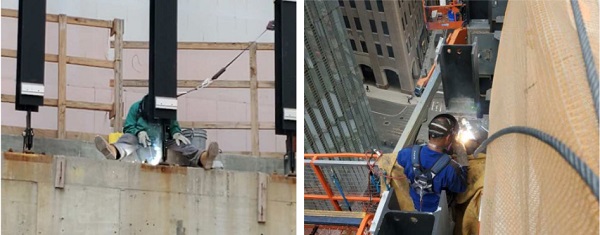
When about 50 % of the brackets were installed, the site crew was increased to allow for simultaneous steel mullion installation (Fig. 7). The warehouse was notified two days in advance to prepare the material for just-in-time shipping to site. Each truck was able to deliver between two and four crates filled with 9 m long sections of mullions including all ancillary materials required for installation.
Usually, each mullion was split in three parts to be connected via a shear bolt connection. Fig. 7 shows the installation of the bottom part which carried the connection elements to the LOBBY and the PLAY level. The other two parts, bridging between PLAY and ROOF, were connected lying flat on the ground, tilted into the vertical position and connected to the roof bracket. This allowed for the quickest installation. Usually, the regular HEB mullions were installed first, followed by the welded reinforced sections close to the corner and finalized by the heavy corner mullions. Even though the size and the weight differed considerably, a consistent and repeating installation process ensured a high level of safety and quality. Before welding, all mullions were finally adjusted in all three axes to guarantee perfect alignment and orientation before curtain wall installation.
The LOBBY level at the South elevation and parts of the western side of the building were suspended from the PLAY level via hanger rods, hence forming a different installation condition. This creates the illusion of a floating bridge. Unfortunately, this building element was not able to take the dead load of the facade steel mullions during installation before the load was finally transferred to the top bracket.
The installation planning team at Gartner developed different installation methods to deal with this situation. This included erection of shoring towers, additional temporary brackets for load transfer and suspending the entire floating bridge up to the ROOF level with steel trusses so the additional temporary dead load of the mullion did not impact the structural integrity of the LOBBY level structure.
All these methods would have required additional material for temporary structures and additional coordination with different building authorities, so that at the end the best and easiest solution was to assemble all three section on the ground to one 32 m long steel beam. To achieve this, the bottom section was put up vertically on the ground and held in place by a small crane while the bigger crawler crane placed the pre-assembled middle and upper section on top of it (Fig. 7). Two ironworkers connected the lower with the upper sections from a boom lift before the crawler crane lifted the entire column to its final destination. This process did not require any temporary loading of the LOBBY level bridge and so ensured that the entire dead load from the vertical steel mullion was introduced directly into the top bracket.
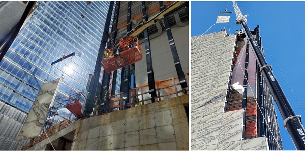
All of the 128 mullions were installed, adjusted and welded in less than three months (Fig. 8). For this purpose, two crawler cranes, located to the north and the south of the building were used. With a maximum capacity of 400 metric tons, it was possible to pick the elements from the delivery areas directly to the installation area without the need of any additional drop off locations.
3.3. Curtain wall
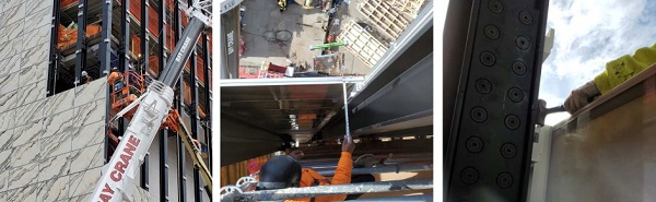
Each curtain wall unit was labelled according to its final position at the building envelope. They were stacked and packet in the shop in Gundelfingen and shipped horizontally to the USA. However, this made it necessary to pre-define the erection sequence and avoid inefficient resorting on site. This did not allow for any flexibility in the installation sequence and made a precise planning and coordination necessary. Each truck could be loaded with six crates that contained four units each. After opening the crates, the top element was hoisted in the vertical position and directly lifted to its final position (Fig. 9). Each elevation – North, South, East and West – was filled with units independently starting from the bottom row of the building.
After adjusting and checking the position of the units, a pre-drilled hole in the aluminum bracket was extended to meet with the bracket on the side of the steel mullion. A pin was fed through the hole to create a reliable mechanical connection to the building (Fig. 10). The installation process as well as the installation sequence were planned well enabling the installation crew to install more curtain wall panels as required by the schedule and finish installation ahead of schedule.
3.4. Lessons learned
Once again, this project proves that intensive and detailed planning is required throughout all project phases. This does not only include system design and engineering with the architect and client but also internal logistic processes and production and installation methods. This is especially important at a project like “The Ronald O. Perelman Performing Arts Center” with its extraordinary design at which is glass unit as entirely unique and cannot be easily replaced. Double checking as-built conditions are time consuming first but will pay out. Also, this is allowing for early detection of misalignments to be dissolved with the client in a cooperative manner. The team can thus me mobilized just in time and kept at a constant count and workload. In this project it was exceptionally challenging as the level of tolerance between the basic structural steel and the curtain wall needed careful attention.
The installation of the full length mullions at the South elevation with its floating deck and hanger rods was challenging. Therefore, it was decided to train the installation crews off site at the warehouse and to test and review the installation process. This exercise reduced the learning curve which typically an installation team of bespoke glass facades has to go through. Furthermore, it enabled the installation crew of Local 7 Ironworkers to fine tune the installation processes and reduce any risks.
As Gartner USA and Permasteelisa North America Corp, we have a very well trained pool of experienced Local 7 Ironworker in New York City who recently completed successfully projects like the new LaGuardia Terminal B or the One Vanderbilt Tower.
Also the extensive pre-planning of curtain wall installation proofed to allow for a quick and reliable installation. The steep learning curve of the site team set the basis for quick adaption of proposed procedures according to requirements on site.
4. The Summary
A new landmark building reveals its curtain of glass, textured by stone at the new World Trade Center site in New York City. In total 128 architecturally exposed steel mullions were installed carrying 1,280 facade units and more than 5,000 stone-glass IGUs on a 7,000 m2 surface.
To do this, 227 mega-blocks of marble were cut from a Portuguese quarry, sliced into tiles for glass production. As the distinct veining is the prominent feature of the design, it was decided in the quarry what stone needs to be placed at what location on the elevation. This required a customized, digital workflow. The final outcome as it can be visited today (Fig. 11).
Comparing the architects first renderings with the realized facade show an astonishing match. The white background shines and underlines the crisp black veining. During the night when the inside is illuminated and during the day when a visitor enters the building, a smooth amber glow creates a welcoming effect. The whole team is proud of the result after playing the world largest game of “Matching Pairs”.
Acknowledgements
- Building Owner: The Perelman Center at the World Trade Center, New York
- General contractor and client: Sciame Construction, LLC, New York
- Design architect: REX, New York City
- Executive architect: Davis Brody Bond, New York
- Facade Consultant: FRONT, Brooklyn
- Facade Contractors: Josef Gartner GmbH, Gundelfingen, Germany & Josef Gartner USA, a division of Permasteelisa North America Corp., Windsor, CT
References
Engelmann, M., Kübler, A., Hirsch, F.: Stone-glass curtain wall: designing an outstanding facade in New York City. Glass Struct Eng 6, 339–352 (2021). https://doi.org/10.1007/s40940-020-00141-7


Comments
Process optimization and automation of setup and troubleshooting are the next logical stages in digitalizing this industry.