Article Information
- Digital Object Identifier (DOI): 10.47982/cgc.9.491
- Published by Challenging Glass, on behalf of the author(s), at Stichting OpenAccess.
- Published as part of the peer-reviewed Challenging Glass Conference Proceedings, Volume 9, June 2024, 10.47982/cgc.9
- Editors: Christian Louter, Freek Bos & Jan Belis
- This work is licensed under a Creative Commons Attribution 4.0 International (CC BY 4.0) license.
- Copyright © 2024 with the author(s)
Author: Gergely Molnár - CNRS, INSA Lyon, LaMCoS
Abstract
This paper investigates the challenges and potentials of phase-field modelling in simulating glass fracture. The phase-field method, a variational approach to fracture modelling, treats cracks as diffused interfaces, thus eliminating the need for explicit crack tracking. This study explores its application to glass, a material with unique fracture characteristics due to its amorphous structure and brittleness. We implemented the AT1 phase-field model using Abaqus and validated it against various experimental setups, including micro-cantilever and micro-pillar tests, L-shaped samples, and dynamic tensile fracture scenarios. The results demonstrated strong alignment with experimental observations, accurately capturing complex crack patterns and dynamic fracture behaviors. Key parameters like the critical energy release rate and internal length scale were shown to significantly influence fracture simulation outcomes. While the phase-field method shows promise in advancing glass fracture mechanics, challenges remain in parameter sensitivity and integrating more sophisticated material models. This study highlights the method's current capabilities and points to future research directions for enhancing its applicability and efficiency in glass fracture simulations.
1.Introduction
The phase-field method (Bourdin et al., 2000; Miehe et al., 2010; Molnár & Gravouil, 2017a) has emerged as a robust tool for simulating fracture, offering a versatile framework to explore initiation, propagation, and branching in brittle materials without relying on ad-hoc criteria. This paper delves into the intricacies of phase-field fracture modelling, particularly emphasizing its application to glass—a material with unique fracture characteristics.
The phase-field approach to fracture modelling treats the crack as a diffused interface within a continuous field, eliminating the need for explicit crack tracking. This method is particularly advantageous for simulating complex crack patterns, including branching and merging, in a natural and seamless manner. By incorporating the principles of energy minimization and variational calculus, the phase-field method provides a robust theoretical foundation for understanding fracture phenomena.
Glass, a ubiquitous material in both everyday applications and advanced technologies, presents unique challenges for fracture modelling. Its amorphous structure and inherent brittleness result in fracture behaviour that is highly sensitive to flaws and external conditions. Accurate simulation of fracture in glass is crucial for improving the safety and reliability of glass products, from architectural elements to electronic devices.
Despite the advantages of the phase-field method, its application to glass fracture has been limited. The few existing studies often question the efficiency and accuracy of the method in capturing the nuances of glass fracture (Freddi & Lorenzo Mingazzi 2020; Mehrmashhadi, 2020; Nikam, 2020; Schmidt et al., 2020; Egboiyi et al., 2022; Schmidt et al., 2023). This paper aims to bridge this gap by providing a detailed examination of phase-field fracture modelling in glass. We explore the theoretical underpinnings of the method, address the specific challenges associated with glass, and present a series of illustrative examples that demonstrate its potential and limitations.
By examining both static and dynamic fracture scenarios in silicate glass samples, we aim to provide a comprehensive overview of the capabilities of the phase-field method. Our results show a strong alignment with experimental observations, suggesting that this method can serve as a valuable tool for advancing our understanding of glass fracture mechanics. This study not only highlights the current state of phase-field modelling for glass but also points towards future research directions that could enhance its applicability and efficiency.
2. Method
2.1. Theoretical background
Bourdin et al. (2000) introduced a widely used theory for modelling fracture using variational methods, building on damage mechanics (Kachanov, 1958) and regularizing discontinuities with a continuous field (Ginzburg and Landau, 1950; Cahn and Hilliard, 1958). This theory replaced Griffith's discrete fracture surface (Griffith 1921) with a continuous damage density function within a variational framework (Francfort and Marigo, 1998), using the Mumford and Shah functional within the Ambrosio and Tortorelli elliptic regularization framework.
The phase-field fracture model represents cracks with a damage variable (d) ranging from 0 (undamaged) to 1 (fully formed crack). This allows for simulating crack initiation and propagation without explicit crack tracking. Damage evolution is governed by partial differential equations coupled with mechanics. The minimization of the solid body's energy drives damage formation and crack opening.
Several phase-field models exist. This paper employs the AT1 model (Pham et al., 2011), featuring a quadratic energy degradation function and a linear crack surface density equation. The AT1 model, validated and widely used, provides an initial elastic threshold essential for accurately simulating damage onset. We enforced positive damage increments and irreversibility using Lagrange multipliers.
The following energy functional is minimized in each load increment to obtain equilibrium:

where ψ₀ is the undamaged strain energy, u is the displacement vector, gc and lc are the critical energy release rate and the internal length scale. In order to avoid damage in compression the strain energy is decomposed using the spectral method (Molnár et al. 2022).
For comprehensive phase-field theory, see Bourdin et al. (2000) and Miehe et al. (2010). For implementation details, refer to our recent publication (Molnár et al., 2022).
2.2. Numerical implementation
The numerical implementation in this study uses a staggered solution scheme, solving the mechanical and damage problems in a weakly coupled manner. First, the energy minimum is found in the mechanical problem using a constant damage field. Then, the elastic, undamaged strain energy is transferred to the phase-field problem to calculate damage topology. Damage irreversibility is enforced using Lagrange multipliers.
The implementation was done in the commercial finite element code Abaqus. Due to limitations of the UEL option in Abaqus/Standard, the two problems were solved independently but simultaneously. The damage variable and elastic strain energy were updated at the beginning of each step and then kept constant. Two finite element layers were used: one for the mechanical problem with a constitutive model in a UMAT, and one for the phase-field element included as a UEL subroutine.
Given that the two linear problems do not interact during the search for the minimum, a sufficiently small time step is crucial as the global problem is highly non-linear. This was controlled by an automatic algorithm that adjusts the time step based on the local undamaged energy increment. For validation and further details, see Molnár et al. (2020, 2022, 2024).
2.3. Homogeneous solution
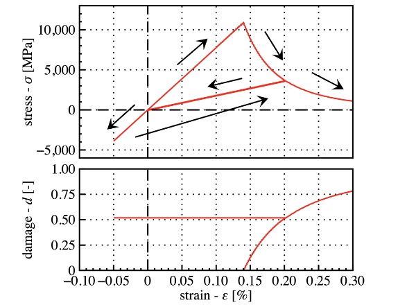
To analyse the phenomenological effect of gc and lc, we calculate the homogeneous solution of eq. (1), neglecting the gradient term. This simplifies the solution, allowing damage to be expressed directly as a function of elastic strain energy. The results are shown in Fig. 1. The axial stress is plotted against axial strain for a loading loop: the sample is loaded to 20% strain, relaxed, compressed to -5%, and then reloaded. After reaching a stress maximum, the material's strength gradually decreases. During unloading, this is correlated with stiffness degradation. However, in compression, both strength and stiffness remain intact due to the spectral energy decomposition scheme.
This simple equation can also estimate the internal length-scale lc. Knowing the material's stiffness, strength, and toughness, lc can be calculated. Recent papers have shown good correspondence between these quantities in various loading cases (Molnár, 2020, 2024).
2.4. Validation
The implementation used in this paper was thoroughly compared to experiments and validated on various loading cases and materials. It accurately captured phenomena such as size effects in tensile fracture (Bažant 1997), branching and kinking angles in in-plane shear (Erdogan & Sih 1963), and facet formation in antiplane shear (Knauss 1970). Interested readers are referred to the work of Molnár et al. (2017a, 2020, 2022, 2024) for details.
3. Examples
This paper presents two groups of examples: (i) micron-scale tests in amorphous silica samples, and (ii) macroscopic fracture experiments in window glass (soda-lime-silica). The key difference between the two groups is the length scale. In macroscopic tests, ductile deformation is negligible, while in micron-scale samples, bond reformation in shear necessitates a ductile-brittle material model.
For amorphous silica, the elastic properties used were E = 72 GPa and ν= 0.18. For window glass samples, E was set to 70 GPa and the Poisson’s ratio to 0.23. Additionally, for silica, a yield criterion developed by Kermouche et al. (2008) and implemented in Molnár et al. (2017b) was coupled to the phase-field response as detailed in Molnár et al. (2020b). Notably, unlike in the aforementioned study, the yield strength was not degraded with the phase-field variable in this work.
The phase-field model accounts for composition dependence through material properties but does not explicitly model the chemical components as molecular dynamics does.
3.1. Micro cantilever
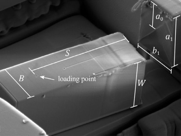
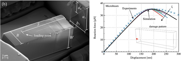
The first test involved amorphous silica using a micro-cantilever beam with a chevron notch (Mueller et al. 2015). For the phase-field model, a symmetric arrangement with 780,000 solid finite elements was used. Results showed no plastic deformation at the crack, indicating that the experimentally measured fracture toughness corresponds to brittle failure. Interestingly, lc does not influence the maximum force at fracture but affects the post-fracture behaviour. A gc value of 7 J/m accurately reproduced experimental measurements.
3.2. Micro-pillar compression
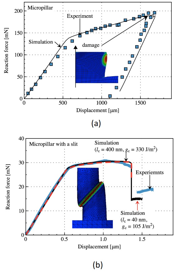
The next test case involves axially compressed micropillars. Fig. 3a shows the results for a flawless pillar(Kermouche et al., 2016), while Fig. 3b presents the results for a pillar with a slit (Guillonneau et al., 2022). Both fracture patterns agree with experimental measurements. Unlike the pre-notched cantilever, multiple lc/gc pairs could be identified in this case. This is because, without an initial crack, the phase-field simulation reverts to the homogeneous solution. Significant yielding is observed in both cases.
3.3. L- shaped sample
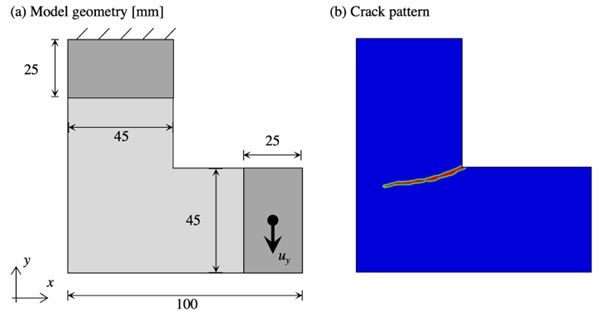
Our next test case presents the L-shaped geometry as detailed by Rudshaug et al. (2023). Figure 4a depicts the finite element model and boundary conditions, where the upper side is fixed in both the x and y directions, while the lower lip is pulled downward with allowed rotation. The fracture toughness 𝑔𝑐 is set to 7 J/m², and the regularization length 𝑙𝑐 is 0.5 mm.
Figure 4b displays the emerging crack pattern, demonstrating excellent correspondence with experimental observations. Notably, the initial unstable burst of the crack transitions into a stable propagation phase, consistent with experimental results.
3.4. Dynamic branching
Fig. 6(a) illustrates the geometry of the dynamic tensile sample utilized in this study. The finite element mesh, comprising 313,000 elements with a maximum size of 0.125 mm, was randomly generated. The material density was set to 2,500 kg/m3. Fracture parameters were specified as 𝑔𝑐 = 7 J/m2 and 𝑙𝑐 = 0.5 mm. A fixed time step size of 𝛥t = 3.5e−8 s was employed. Uniform tensile loads of 𝜎𝑦 = 2.3 MPa were applied to the top and bottom sides.
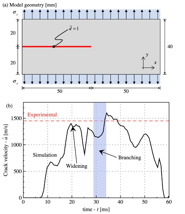
Figure 5b illustrates the dynamic progression of the crack, showcasing its acceleration, branching, and eventual reach to the sample's sides post-initiation. During the acceleration phase, the crack widens until the energy release rate doubles that of 𝑔𝑐, prompting branching. Remarkably, even without additional parameters to account for initiation acceleration and branching, the experimental crack velocity was accurately reproduced using only 𝑔𝑐 and 𝑙𝑐.
4. Conclusion
This study explored the potential of phase-field modelling for simulating fracture in glass materials. By adopting a variational approach, we provided a robust framework for capturing complex fracture behaviours without explicit crack tracking.
Our numerical implementation, validated through various examples, demonstrated the method's reliability in simulating both static and dynamic fractures. The analysis of critical parameters like gc and lc showed alignment with experimental observations, offering insights into fracture behaviour under different conditions. Simulations of micro-cantilever and micro-pillar tests accurately reproduced experimental measurements, while L-shaped and dynamic branching tests captured complex crack patterns effectively. The model successfully simulated crack acceleration and propagation in dynamic tensile tests, matching experimental crack velocities.
While the phase-field method proved effective, further research is needed to refine parameter sensitivity and integrate more sophisticated material models. Overall, the phase-field approach offers a powerful, versatile tool for advancing our understanding of glass fracture mechanics and enhancing the development of safer glass products.
References
Bažant, Z. P.: Scaling of quasibrittle fracture: asymptotic analysis, Int. J. Fract. 83, 19. (1997)
Bourdin, B., Francfort, G., Marigo, J.-J.: Numerical experiments in revisited brittle fracture. J. Mech. Phys. Solids 48 (4), 797–826. (2000)
Cahn, J.W., Hilliard, J.E.; Free energy of a nonuniform system. I. Interfacial free energy. J. Chem. Phys. 28 (2), 258–267. (1958)
Egboiyi, B., Mattey, R., Konica, S., Nikam, P., Ghosh, S., & Sain, T.: Mechanistic understanding of the fracture toughening in chemically strengthened glass—experiments and phase-field fracture modeling. International Journal of Solids and Structures, 238, 111374. (2022)
Erdogan, F., Sih, G.C.: On the crack extension in plates under plane loading and transverse shear, J. Basic Eng. 85, 519–525. (1963)
Francfort, G., Marigo, J.-J.: Revisiting brittle fracture as an energy minimization problem. J. Mech. Phys. Solids 46 (8), 1319–1342. (1998)
Freddi, F., & Mingazzi, L.: Phase field simulation of laminated glass beam. Materials, 13(14), 3218. (2020)
Ginzburg, V.L., Landau, L.D.: On the theory of superconductivity. J. Exp. Theor. Phys. (U.S.S.R) 20, 1064. (1950)
Griffith, A.A.: The phenomena of rupture and flow in solids. Philos. Trans. R. Soc. Lond. Ser. A Math. Phys. Eng. Sci. 221 (582–593), 163–198. (1921
Guillonneau, G., Sao Joao, S., Adogou, B., Breumier, S., & Kermouche, G.: Plastic flow under shear-compression at the micron scale-application on amorphous silica at high strain rate. JOM, 74(6), 2231-2237. (2022)
Kachanov, L.M.: Rupture time under creep conditions. (1958)
Kermouche, G., Barthel, E., Vandembroucq, D., & Dubujet, P.: Mechanical modelling of indentation-induced densification in amorphous silica. Acta Materialia, 56(13), 3222-3228. (2008)
Kermouche, G., Guillonneau, G., Michler, J., Teisseire, J., & Barthel, E.: Perfectly plastic flow in silica glass. Acta Materialia, 114, 146-153. (2016)
Knauss, W.G.: An observation of crack propagation in anti-plane shear. Int. J. Fract. Mech. 6 (2), 183–187. (1970)
Mehrmashhadi, J., Bahadori, M., & Bobaru, F.: On validating peridynamic models and a phase-field model for dynamic brittle fracture in glass. Engineering Fracture Mechanics, 240, 107355. (2020)
Miehe, C., Welschinger, F., Hofacker, M.: Thermodynamically consistent phase-field models of fracture: Variational principles and multi-field FE implementations. Internat. J. Numer. Methods Engrg. 83 (10), 1273–1311. (2010)
Molnár, G., A. Gravouil, A.: 2d and 3d abaqus implementation of a robust staggered phase-field solution for modeling brittle fracture, Finite Elem. Anal. Des. 130 27–38. (2017a)
Molnár, G., Kermouche, G., Barthel, E.: Plastic response of amorphous silicates, from atomistic simulations to experiments –A general constitutive relation, Mechanics of Materials, 114, 1-8. (2017b)
Molnár, G., Doitrand, A., Estevez, R., Gravouil, A.: Toughness or strength? regularization in phase-field fracture explained by the coupled criterion. Theor. Appl. Fract. Mech. 109, 102736. (2020a)
Molnár, G., Doitrand, A., Jaccon, A., Prabel, B., Gravouil, A.: Thermodynamically consistent linear-gradient damage model in abaqus. Eng. Fract. Mech. 266, 108390. (2022)
Molnár, G., Gravouil, A., Seghir, R., Réthoré, J.: An open-source abaqus implementation of the phase-field method to study the effect of plasticity on the instantaneous fracture toughness in dynamic crack propagation. Comput. Methods Appl. Mech. Engrg. 365, 113004. (2020b)
Molnár, G., Doitrand, A., Lazarus, V.: Phase-field simulation and coupled criterion link echelon cracks to internal length in antiplane shear. J. Mech. Phys. Solids 188, 105675. (2024)
Mueller, M. G., Pejchal, V., Žagar, G., Singh, A., Cantoni, M., & Mortensen, A.: Fracture toughness testing of nanocrystalline alumina and fused quartz using chevron-notched microbeams. Acta Materialia, 86, 385-395. (2015)
Nikam, P.: Phase Field Fracture Modeling of Chemically Strengthened Glass. (2020)
Pham, K., Amor, H., Marigo, J.-J., Maurini, C.: Gradient damage models and their use to approximate brittle fracture. Int. J. Damage Mech. 20 (4), 618–652. (2011)
Rudshaug, J., Hopperstad, O.S. & Børvik, T.: Effect of load level on cracking of L-shaped soda-lime glass specimens. Glass Struct Eng (2023)
Schmidt, J., Zemanová, A., Zeman, J., & Šejnoha, M.: Phase-field fracture modelling of thin monolithic and laminated glass plates under quasi-static bending. Materials, 13(22), 5153. (2020)
Schmidt, J., Janda, T., & Šejnoha, M.: Prediction of pre-and post-breakage behavior of laminated glass using a phase-field damage model. Applied Sciences, 13(3), 1708. (2023)

