
Authors: K. Ghazi Wakili, W. Raedle, A. Krammer, A. Uehlinger, A. Schüler and Th. Stöckli
Source: Journal of Building Engineering, Volume 44, December 2021, 103031, ScienceDirect
DOI: https://doi.org/10.1016/j.jobe.2021.103031
Highlights
- Comparison of measured and declared Ug-Value of low-e coated triple glazing units.
- Measurement and calculation standards to be complementary not mutual replacing.
- Difficulties for measuring the emissivity of coatings according to the relevant standard.
Abstract
Triple glazed low-e coated insulating glass units with argon filling of five different suppliers on the European market with a declared thermal transmittance in the undisturbed centre of glass (Ug-value) of 0.6 W/m2K have been purchased from resellers and tested in a guarded hot plate at vertical position. The measured results showed deviations towards higher values for all 5 types. These have been analysed by recurring to the determination of the two main factors namely the gas mixture in the two cavities and the emissivity of the coated glass panes. Non-destructive measuring methods for gas mixture analysis and standardized calculation methods for the Ug-value have been used to analyse the influence of these two factors. In a further step the edge heat loss due to the spacer of the insulating glass units has been measured by using two “halves” of each glazing type with a double edge running through the middle of the measured sample. This was done following a standardized test method for the determination of the edge heat loss of Vacuum Insulation Panels (VIP). Finally, pieces of the coated glass panes were cut out of the glazing units and their emissivity measured with both an infrared spectrometer and an emissiometer. Results showed an increased emissivity value for the coated surfaces leading to higher Ug values than measured. This is partly due to the exposure to air and the possible degradation of the coating. The investigation shows non-destructive emissivity determination is needed to get more accurate in-situ emissivity values of the coatings.
1. Introduction
The thermal improvement of multiple glazing windows shows an impressive track over the past several decades. The Ug-value (undisturbed centre of glass), being the main property in this respect, has come down from 3.0 W/m2K for air filled uncoated double glazing with 10 mm space to about 0.6 W/m2K for Argon filled coated triple glazing with 14 mm spaces, hereby taking the most commonly used glazing types into account. One of the key factors for this was the improvement of the coatings applied on the glass panes [1] reducing the radiative heat transfer in the air/gas filled cavities. Another factor was a partial or total replacing of air by the heavy inert gases (Argon, Krypton and Xenon) which reduce the convective heat transfer in the cavities due to their heavier atomic weight. A total suppression of conductive and convective heat transfer can be achieved by maintaining a vacuum layer between the glass panes. In their review on “Fenestration of today and tomorrow” Jelle et al. [2] mentioned combined vacuum triple glazing and suspended films in the cavities which showed Ug-values as low as 0.28 W/m2K.
There were also Krypton- and Xenon-fillings mentioned which reduce the convective heat transfer in the cavities but are still too expensive to enter the market. Triple glazing units with Krypton fillings and low emission coatings have also been reported by Ref. [3]. Manz et al. [4] also mention in their energy performance analysis a triple glazing filled with Krypton having a Ug-value of 0.4 W/m2K. A more recent review by Cuce et al. [5] summarizes the latest developments whereas the references given are mostly based on manufacturer data sheets. Many of these Ug-values are based on calculations only. Lolli et al. mention in their comparative investigation triple-glazing units with argon fillings and a Ug-value of 0.79 W/m2K and double-glazing units with either monolithic aerogel having a Ug-value 0.65 W/m2K or granular aerogel with a Ug-value of 0.31 W/m2K [6]. A more recent investigation based on measurements carried out on double-glazed coated vacuum glasses with a vacuum cavity of 0.2 mm with transparent pillars to maintain the gap against ambient pressure, show that they hardly reach Ug-values better than 0.5 W/m2K [7].
This considerable improvement of one of the basic characteristics of multiple glass units (excluding vacuum glazing as there is yet no corresponding standard) has been followed by simultaneously improved measurement and calculation methods leading to different International and European standards used by research institutes and industry alike. The basic idea of the standards being the reciprocal influencing of simulations and measurements including balances and checks.
The guarded hot plate apparatus [8] is a versatile device to measure the thermal resistance of a wide range of materials and has been the most adequate instrument to measure the centre-of-glass Ug-value of double and triple glazing units. There is a particular standard dealing specifically with the determination of the Ug-value of glass in buildings [9]. One of the earliest investigations using the guarded hot plate reports the influence of different coatings to reduce radiative heat transfer in the air layer between the glass panes of double-glazing units [10]. The authors also measured the influence of the mean temperature, i.e. summer or winter conditions on the measured Ug-values. Towards the end of the 20th century glazing units with Argon and Krypton fillings came up and were investigated especially in the Nordic countries in need of improved thermal insulation in defiance of their harsh winter climate.
Numerical and experimental investigations as complementary methods have been reported by Larsson et al. [11] indicating large edge effects due to the heat loss through the aluminium profiles for holding the panes. This implied also lower temperatures on the edges at the room side the authors measured to be around 5 °C leading to an increase of the condensation risk for relative humidity conditions above 40 % at a room air temperature of 20 °C. Measurements were carried out in a special test room with temperature differences of about 30 and 50 K between room side and cold side resulting in a variation of the Ug-value between 0.7 and 0.8 W/m2K.
Regarding the gas fillings, there is a need for a non-destructive testing method to determine the percentage of the inert gas in the cavities of the glazing unit after the end of production and at the time of installation. One such technique is based on interferometric sound velocity measurements and has been dealt with in a publication by Glora et al. [12]. The technique makes use of the fact that sound velocity is higher in air than it is in Argon or Krypton. By means of an interferometer and ultrasonic transducers a dc voltage proportional to the change gaps of thein travelling time through the gap is measured. The accuracy of this method has been reported to be around ±20 % for Argon filled and ±5 % Krypton filled windows [12]. By this method one of the major two factors responsible for the low thermal transmittance can be determined to a certain accuracy.
As already mentioned, the other influential property which is decisive for the low thermal transmittance through the gaps of the glazing is the emissivity of the coated glasses. Nilsson et al. have shown that in a heating dominated climate a low-e coating with a high g-value can result in a net energy gain on a south oriented façade and hence be better than an ideal wall [13]. The corresponding standard dealing with the emissivity of coated glasses EN 12898 [14] is quite elaborate and requires a spectrometer covering an infrared spectrum from 5 μm to 50 μm which is still hard to comply with by common FTIR spectrometers. Gelin et al. [15] have estimated the errors which might occur by extrapolating the measured reflectance spectra using three different extrapolation procedures.
A pure geometric parameter that has an impact on the Ug-value of glazing units is the centre-of-glass deflections depending on the outdoor climate variations. Hart et al. [16] reported for Argon filled double glazing units of 850 mm × 1770 mm size, a deviation of 1.5 mm for gaps between 12 and 14 mm when the indoor-outdoor temperature difference is about 20 K.
Besides laboratory measurement under well-defined climatic conditions there have also been attempts to determine the Ug-value of glazing panels installed in a building with a portable device (in-situ measurement). One such equipment has been presented by Kim et al. [17] for double glazing units with and without low-e coatings filled with air or Argon. In comparison to calculated values the results were quite satisfactory but there was no comparison with laboratory measurements or any other standardized measuring method.
The present investigation deals with the Ug-value low-e coated and argon filled triple glazing units of 5 different producers present on the European market. In order to get a representative and unbiased selection all samples were bought from distributors and not directly from the companies themselves. So, the orders were placed by the distributors among many other orders and hence unrecognizable to the producers. This guarantees an unbiased selection of samples independent of the producers and the testing institute itself. Square shaped and rectangular shaped glazing units were purchased to determine the Ug-value at the glass centre and the additional heat loss through the edge respectively. A comparison of the measured data with the declared values is made and experimental and calculation methods are used to find and quantify the possible sources responsible for these discrepancies.
2. Material and methods
Form each brand 3 square shaped (samples A - C) and 6 rectangular shaped (samples D – I) triple glazing units of 800 mm × 800 mm and respectively of 400 mm × 800 mm were purchased. The total nominal thickness of all units was 40 mm (4/14/4/14/4).
2.1. The guarded hot plate apparatus (GHP)
A guarded hot plate with a maximum sample size of 900 mm × 900 mm and a metering area of 500 mm × 500 mm was used for the determination of the thermal properties of the triple glazed insulation glass units. This apparatus can be used for two-sample or single-sample measuring modus and has an electromechanical control unit which after installation of the sample can rotate the whole apparatus including the samples from a horizontal into a vertical position. All measurements in this study were carried out in the vertical position. By this, a requirement of the measuring standard EN 674 [9] was fulfilled. The physical quantity measured by this apparatus was the thermal resistance of the sample. In case of glazing units the corresponding Ug-value is determined by adding the total (internal + external) surface resistance of 0.17 m2K/W to the mentioned measured value as required by Ref. [9].
To keep the heat loss through the edge of the glazing units at a minimum, an overall size of 800 mm × 800 mm (square samples) or 2 × 400 mm x 800 mm (rectangular samples) has been chosen. This allowed to add an insulation (EPS) belt of 50 mm width around the samples to prevent the influence of the circulating air inside the GHP on the measurement results. The air in the gap between the outer wall of the apparatus and the lateral surfaces of the encased sample is kept at the level of the sample mean temperature by means of an auxiliary guard heater preventing lateral deviations of heat flux in the sample. This ensures a nearly unidirectional heat flow perpendicular to the sample in the metering area.
According to the measuring standard [9] the measurements must take place at a mean temperature of 10 °C and a temperature difference over the sample thickness of 15 K. For this reason, all the samples were conditioned in a chamber to 10 °C prior to be installed in the GHP. An important point which must be kept in mind is the maximum allowed deviation of the glazing units from planeness, a problem which has already been pointed at [16]. Due to lower temperatures there might occur a dishing effect caused by the compression of the gas in the cavities. The amount of compression, i.e. dishing depends on the temperature the glazing units were filled with Argon at the production stage. This dishing shall be countered by means of refilling the cavities with Argon and not with air to prevent the deterioration of the insulating effect of the cavity as Argon supresses the convective heat transfer in the gap much better than air.
The following procedures were carried out in a conditioning chamber at 10 °C (corresponding to the mean temperature during the actual measurements in the GHP) prior to the installation of the samples to provide the identical conditions they will experience during measurement in the guarded hot plate apparatus:
- Measurement of length, width, and thickness of each glazing unit
- Measurement of the dishing or bowing at the centre of each glazing using a depth gauge, paying attention to avoid bending of the units due to their weight
- Injection of pure Argon into the gaps in order to reduce dishing of the glazing unit to a minimum (±0.5 mm) required by the standard EN 674 [9].
- Attaching and numbering of the thermocouples on both sides of the glazing unit according to the standard requirements [9].
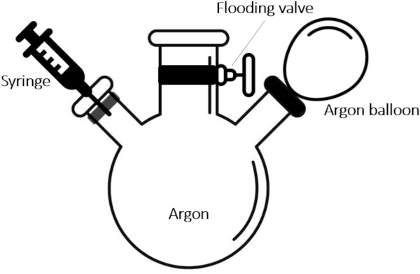
The abovementioned injection of Argon was made by using a syringe filled with Argon taken from an Argon filled glass bottle by piercing a tight rubber tap (Fig. 1 left). The bottle itself was filled by means of a rubber balloon filled with Argon and then flooded by opening the corresponding valve. As air is lighter than Argon it will leave the bottle first, ensuring that only Argon is left in the bottle. The injection will be repeated until the dishing diminishes to the required amount on both sides of the glazing unit. Two different edge sealing/spacer systems have been encountered, one which was rubbery and easily pierced by the needle and closing the hole after the needle was pulled back and another one which was hard and stiff and needed tiny drilling to inject the Argon and had to be sealed at the piercing sites by butyl sealant. The success of this procedure was confirmed by a gas analysing method explained later.
Further, thermocouples were installed on both sides of the individual samples within the metering area as can be seen in Fig. 2, Fig. 3 showing the samples in the opened apparatus prior to adding the heating unit, closing and rotating the whole guarded hot plate into vertical position. There was also an additional sensor fixed on the warm side which measured the temperature difference over the metering gap. This was to check if the lateral flow (i.e. deviation from a unidirectional temperature field) was kept at a minimum possible.
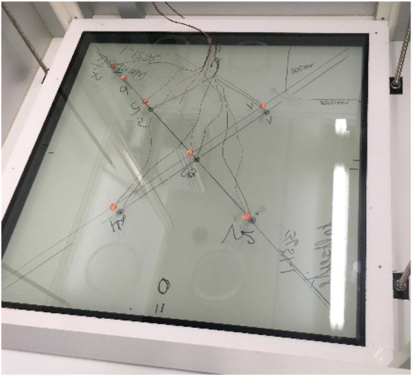
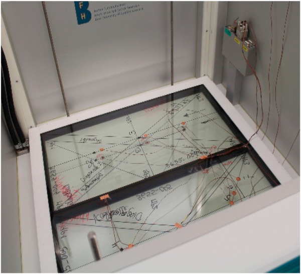
Due to the incompressibility of the glass surfaces a levelling layer is put on both sides of the sensor equipped glazing units according to the requirements of the measuring standard [3]. This ensures an ideal thermal contact between the tested sample and the heating as well as the cooling surface avoiding a falsification of results by thin trapped air layers. A corresponding small correction must be made due to the use of the levelling layers according to the mentioned standard. The single unit tests (Fig. 2) were carried out for the determination of the centre-of-glass Ug-value (no edge effect), and the double unit test (Fig. 3) were done for measuring the additional heat loss through the edge (sealing and spacer) the so-called Ψ-value (Psi-value) or the linear thermal transmittance, a quantity determining the additional heat loss at thermal bridges in general [18].
The edge of the glazing units represents in the present study a thermal bridge i.e. a deviation from parallel layers or in other words a thermal short circuit. The difference between the heat loss through glued double units and the single unit results in the additional heat loss through the edge (twice the length in the metering area 2ℓ). This method corresponds to EN 17140 [19] for vacuum insulation panels which have also a centre-of-panel Ucop-value and an additional heat loss due to their edge sealings. It should be noted that this Ψ-value is a property of the glazing unit alone and does not correspond to the Ψ-value for windows (glazing unit including the frame).
Ψ = (Φ2 - Φ1·ΔT2/ΔT1)/(2ℓ·ΔT2).
Φ2 Total heat loss through the 2 glued double units.
Φ1 Total heat loss through the single unit.
ΔT2 Temperature difference over the 2 glued double units.
ΔT1 Temperature difference over the single unit.
2ℓ Twice the length of the metering area (one edge length per unit).
2.2. Tuneable laser absorption spectroscopy (TDLAS)
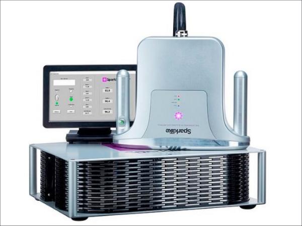
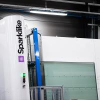
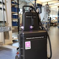
To get a reliable information on the Argon content in the cavities between the glass panes a rather novel in-situ and non-destructive testing instrument “Sparklike Laser Portable” has been used (Fig. 4). The physical principle of the measurement is based on the Tuneable Diode Laser Absorption Spectroscopy which measures the oxygen content inside the gap and allows an accurate determination of the concentration percentage of the rare gas [20]. This is a recently available equipment and has been already tested at several research institutes in Europe. According to the suppliers this technology enables measurements through coatings and laminations. The sole major limitation is when both surfaces of the insulating glass unit filter at 760 nm [20].
![Fig. 4. Non-destructive insulating gas measurement device (Sparklike Laser Portable) for double and triple glazed insulating glass units with coatings and laminations [20].](/sites/default/files/inline-images/Fig4_295.jpg)
Measurements were carried out on “as received” samples and on samples which got Argon injections to reduce dishing at an environment of 10 °C and were tested in the guarded hot plate apparatus.
2.3. Infrared spectrometry and emissiometer
The spectral reflectance of the coated glass samples was measured with a Bio-Rad FTS-175C Fourier transform infrared spectrometer equipped with a 3″ gold-plated integrating sphere and a high-performance nitrogen-cooled MCT detector for the Mid-IR range from 2.5 μm to 14 μm. This spectral range is not in compliance with the mentioned standard stated earlier [14], but according to Ref. [15] the deviations for 3 different extrapolation procedures remain negligible for silver low-e coating. From the MIR reflectance spectrum, the thermal emittance was inferred, using Kirchhoff's law and considering the spectrum of black body radiation at the given temperature [21]. For the window application, ambient temperature of 300 K is assumed.
For additional control, the calibration of this method has been double-checked by measurements with an emissiometer TIR 100 (INGLAS). The emissiometer TIR 100 allows to measure the MIR reflection of the heat radiation originated from a black hemisphere kept at 100 °C. The reflected infrared radiation is observed at an angle and is converted into a numeric value. This value is then plotted against a calibration table from high and low emissivity reference standards. In general, the thermal emissivity is a function of the temperature of the emitting surface. In practice, it is often assumed that the thermal emissivity of many materials undergoes only minor changes between temperatures of 27 °C and 100 °C. This method and equipment comply with EN 16012 [22] which has been established for reflective insulation products and does not comply with EN 12898 [14] mentioned earlier.
2.4. Theory/calculation
Besides the experimental methods, there are also standardized calculation methods for the determination of the Ug-value of glazing units [23]. The calculation procedure is elaborate but straight forward and most of the purchasable calculation software dealing with heat transfer in building elements or generally with energy in buildings incorporate a corresponding procedure. The software used here is an open access software provided on the internet [24] which can easily be used and checked for conformity with the above-mentioned standard procedure. This U value calculator carries out centre of the glazing unit U value calculations, and follows the method described in EN 673:2011 [23].
It can also calculate the U value for the whole window, including frame, glazing and spacer. All the dimensional (glass thickness, cavity depth) parameters of a double or a triple glazing unit can be defined by the user. Each glass pane has two sides each with its own allocated emissivity to be defined by the user. The gas mixture of the cavities can be defined as pure air, Argon, Krypton, Xenon, or a mixture of them. By fixing some of the parameters and varying others one can find the influence of each parameter on the calculated Ug-Value. The software has more features regarding frames and whole windows U-value which were not used here.
3. Results
The Ug-value communicated by all the producers of the investgated glazing units was 0.6 W/m2K, the gas filling was declared to be Argon without details on percentage and finally they all mentioned coatings on the inner and outer glass without indicating any values for their respective emmisssivity. Using the abovementioned software, an attempt was made to reach the declared Ug-value of 0.6 W/m2K by choosing the most probable values for the Argon percentage (90 %) and the emmisivities (0.02). The result is represented in Fig. 5 where all the thermal and geometrical parameters have been indicated. By normal emissivity a value 0f 0.89 is assumed for non-coated glass surfaces. The obtained value corresponds quite well to the declared value as the latter is given in one decimal digit only according to the requirement of the corresponding standard [9]. The sum of the external and internal surface resistances considered in the calculations is 0.17 m2K/W and the temperature difference is 15 K over the whole glazing unit as required by Ref. [23].
![Fig. 5. Ug-value calculation for a triple glazing according to EN 673 [23] with a value corresponding to the declared Ug-value of triple glazing units. Normal emissivity means ε = 0.89.](/sites/default/files/inline-images/Fig5_288.jpg)
The results of the guarded hot plate measurements on two single glazing units for each of the 5 different brands are summarized in Fig. 6. The red line indicates the common value declared by all producers for their respective product. The transparent bar shows the limits of values which can be rounded down to one digit and result in 0.6 W/m2K for the Ug-value. Accordingly, it is only the units of brand 4 which narrowly comply with the declared Ug-value. The two units of brand 2 are slightly higher but the other 3 brands are clearly at 0.7 (±0.05) W/m2K as can be recognized by the error bars indicated in Fig. 6. These results are comparable to those mentioned for triple glazing with argon filling and two coated surfaces in Refs. [6,25].
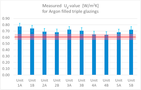
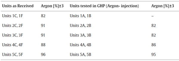
Table 1 summarizes the results of the Argon concentration measurements. It is assumed that the concentration in all units of the same brand is to a good approximation the same. The units C and F represent the “as received” condition whereas the units A and B are those which underwent a GHP test (with Argon injection where needed). The difference between the two conditions (2nd and 3rd column in Table 1) is about 10 %. As will be discussed later the Ug-value is less sensitive to small alternations of the gas concentration than it is to the emissivity of the coated surfaces. Units 1A and 1B could not be tested as they are currently under parallel investigation at another research institute for comparative tests.
Table 1. Results of the non-destructive Argon-concentration measurements on different glazing units of all 5 tested brands (mean values).
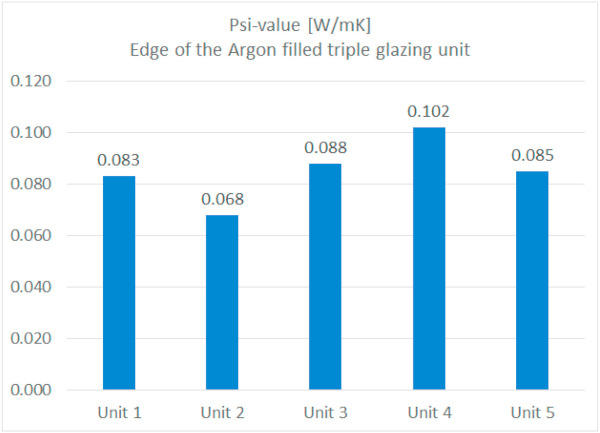
The results of the measurements of the glued pairs of glazing units (2 × 400 mm x 800 mm) as shown in Fig. 3 are summarized in Fig. 7. As expected, the Ψ -value is highest for the lowest Ug-value, because heat flows along the paths with less thermal resistance (or highest thermal conductivity). Nevertheless, a comparison between different edge can only be made when the Ug-value of the glazing units are identical or at least very similar. This method can be helpful in improving a production line by altering the spacer but where all other parameters are kept constant.
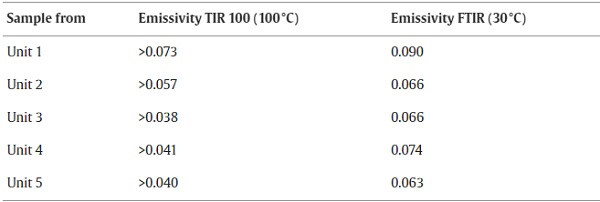
The emissiometer TIR 100 is especially suited for measurements of coatings on metal substrates, such as e.g. selective absorber coatings for solar thermal collectors. For coatings on glass substrates, the sample can warm up slightly during the measurement, causing the signal to drift after some seconds. Therefore, an emissivity measurement of coatings on glass substrates with the TIR 100 is more likely to give a lower bound for the value of the thermal emittance than its value itself. The precision of the FTIR measurement with the integrating sphere is in the order of ± 0.5% point. With such ex-situ measurements, we are of course not able to distinguish whether the low-e coating was already degraded while being still inside the double glazing, or whether it degraded after removal from the double-glazing unit. The results of both methods TIR 100 and FTIR are summarized in Table 2. These are much larger than the values expected to reach a Ug-value of 0.6 W/m2K for the centre of the glazing units. A deterioration of the coatings cannot be excluded. They have been exposed to ambient climatic conditions for several weeks and might have undergone a deterioration regarding the emissivity of the coatings. A non-destructive test equipment was unfortunately not available.
Table 2. Measured emissivity of low-e coated glass samples removed from the investigated double-glazing units by cutting them out.
4. Discussion
To find an explanation to the deviation between the measured and the declared Ug-values of most of the samples, a closer look at the two parameters of influence i.e. the Argon concentration and the surface emissivity is needed.
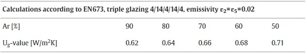
The differences of Argon concentration in “as received” condition and in the ones where Argon has been injected through tiny openings through the edge cannot explain the measured Ug-values being higher than the declared value. This is easily seen when calculating the Ug-value according to EN 673 [23] when all parameters are kept constant and only the argon concentration altered (Table 3). The Argon concentration must be reduced to 60-50 % if the high measured Ug-values must be reached. This shows that the Argon concentration (82 % at minimum, see Table 1) cannot be the reason for the deviation of the measured and declared Ug-values.
Table 3. Calculated Ug-value of triple glazing units according to EN 673 [23] with varying Argon concentration.
Analogously, by keeping the Argon concentration constant it is possible to determine the influence of the emissivity of the coatings on the 2nd and 5th plane of the glazing unit on the Ug-values (Table 4). It has been assumed that both coatings are identical (ε2 = ε5).
Table 4. Calculated Ug-value of triple glazing units according to EN 673 [23] for 90 % Argon in both cavities at varying emissivity of the coatings on the 2nd and 5th plane of the glazing unit.
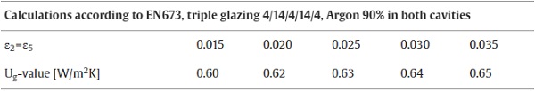
This shows that at 90 % Argon filling in both cavities an emissivity of already 0.030 reaches a Ug-value which is very near the maximum value still to be considered as 0.6 W/m2K (0.65 must be declared as 0.7). Similar values have been reported in a recent numerical analysis [26] where the thermal performance potential of glazing systems with 95 % Argon reaches in the best case a Ug-value of 0.65 W/m2K (corresponding to 0.115 BTU hr−1 ft−2 °F−1). Another research dealing with the possibility and limitations of applying infrared thermography to assess in-situ thermal performance of double and triple glazing units reported calculated values (according to EN 673) of 0.64 W/m2K [27].
The measured emissivity values reported in Table 2 result in much higher Ug-values well beyond the measured ones reported in Fig. 6. This might be caused by degradation of the low-e coatings when exposed to ambient climate or the result of too thinly applied coatings as their thickness is directly related to their emissivity.
Other authors have also found differences between reflectance results obtained from the simulation models and experimental data. The mismatching could be probably reduced if the film spectral properties were obtained directly from the manufacturer [28].
For the future, the application and reporting of precise non-destructive methods will be of major importance to test the emissivity of coatings not only during the production and assembly process but also in their built-in condition in glass units ready to be installed in buildings.
5. Conclusions
The present investigation showed the need for precise testing of highly insulated glazing units according to existing standards and to consider theoretical calculations based on approximate values for the input parameters as a complementary method to testing procedures and not as their equivalent or replacement.
It has been shown that the gas mixture alone cannot be responsible for the higher Ug-values and that the low-emission coatings have also a decisive impact. The test method for the non-destructive in-situ analysis of the gas mixture needs improvement to reach higher precision to be incorporated in international measuring standards. A further item for the improvement of the results presented at this stage is the determination of the emissivity. A reliable, on-site, and non-destructive testing of the emissivity on each coated surface of the glazing unit would be a complementary measurement method to get the full information on all the relevant properties of these highly insulating glazing units in their installed conditions.
It has also been shown that the influence of the spacer on the additional heat loss through the edges of the glazing unit can be determined using a guarded box. This enables further parametric studies aiming at a reduction of heat loss due to the edge effect for each glazing type. A topic of technical and scientific interest for future improvements is the deterioration of low-e coatings when exposed to different gas mixtures in the glazing gaps over a long period of time and subject to climatic conditions.
Statement on measured data
All measured data mentioned in this manuscript is available at the corresponding author upon request.
Declaration of competing interest
The authors declare that they have no known competing financial interests or personal relationships that could have appeared to influence the work reported in this paper.
Acknowledgments
This research has been financed by Bern University of Applied Science itself. The authors highly appreciate the indispensable technical support of Bruno Salzmann (cutting out coated glass samples), Lorentz Scherler (calibration of thermocouples), Andrea Uehlinger and Michael Baumgartner (equipping the samples with sensors) at the institute's lab in Biel.


