The means to control and to apply the RW energy to assist in the thermal tempering process is discussed in detail.
Existing thermal tempering process: Normally the body of the glass panel will have to reach a softening temperature of about 660 º C in the case of Soda Lime glass - this temperature will vary with the composition of the glass - before quenching operation starts. The quench which is usually done with forced air on the glass surface, extracts heat at a rapid rate to freeze the outer surface while the inner portion is still soft.
As the cooling continues, the thermal contraction of the inner portion creates a strong compressive stress on the frozen outer surface while a tensile stress is induced on the inner portion. The resulting panel is said to be heat tempered.

Figure 1 illustrates a typical tempering process sequence and one of the physical difficulties that arise from the required 660º C for the start of the quench operation. Referring to figure 1, the glass is heated in a conventional oven (1) and then it is transferred to a chamber (sec.3) where it is shaped (if required), and then it is transferred to a separate chamber (sec.4) for the quenching operation. At this location the glass needs to be at a minimum of 660º C.
However, the glass looses its temperature very rapidly (as much as 25 Deg/Sec. in thin glasses of less than 3.0 mm thick) before the quenching can start at section 4 The conventional solution to overcome this loss in temperature is to super heat the last zone of the preheat oven (sec.2) by as much as 50 to 100º C., and passing the glass through this zone at a rapid rate.
This strategy makes use of the glass property that during a rapid rise in glass temperature, the viscosity of the glass lags behind. However, in the case of glass thinner than 3.0 mm, this solution is found to be inadequate.
The thermal history of the glass is given in more detail in figure 2. Section 1 shows the pre-heat portion of preparing the glass for the tempering operation. Section 2 describes the additional rise in temperature required in the pre-heating section to compensate for heat loss during the transfer to the quench area. Section 3 indicates the actual temperature loss of the glass panel before the quenching starts in section 4.
The section 2 and 3, which represent the transfer area in fig 2, is where the physical difficulties (earlier mentioned) reside.

At temperatures higher than the 660 º C which is required for the start of the quench in section 4, the viscosity of the glass drops very rapidly and the physical handling of the glass tends to distort the panel. This problem becomes even more severe when the panels are “thin” such as below 3.0 mm thick. Shown in Fig 3 is textbook data (Alexander Fluegel – 2007) of the drop in viscosity of Soda Lime glass during the temperature range of our concern.
It shows in the Log scale that the viscosity actually drops by a factor of more than three between 600 and 660 º C. It is this extreme drop in viscosity that presents a severe processing problem as this soft glass has to be transported from the heating zone into the quenching zone without inducing any optical distortion.

The new process: This new process involves a unique way to shape and/or temper glass panels. Fig 4 describes the new process. In this process the glass is pre-heated in a conventional oven (section no.1) up to a temperature which allows the glass to be transferred or shaped at section no2. It is then transferred at a convenient temperature below the softening temperature of 660 º C.
At this lower temperature, approximately 650 º C the glass is pliable enough to be shaped but stiff enough to resist distortion from normal transfer handling. This relatively cold glass of about 650 º C, (preferably between 620 and 650 º C) is then transferred to the RW oven (Section 4).
Within the RW oven the glass is heated up to the required 660 º C for the quenching action to take place. Since the inside of the RW oven is at room temperature, it also houses the quenching system and the quenching takes place within the chamber before the glass looses any temperature. This is the big difference in the new process from the conventional thermal tempering process.
Fig. 5 presents a detailed thermal history of the new system. Section 1 represents the pre-heat of the glass in a conventional oven. Sec 2 shows the glass forming operation at about 650 º C. Section 3 shows the Glass being heated up to the quenching temperature of 660 º C using RW energy.
The RW energy is preferably applied at about 20 Mega Hertz. At this frequency, the apparatus is commercially available and has a proven record of plant safety. It is used extensively for example, in moisture extraction application in food and paper processing industries. The section 4 shows the quenching operation.
.jpg)
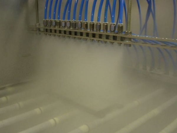
Fig 6 shows one typical configuration of the electrodes inside a RW chamber.
The two beams of electrodes, the positive and the negative are placed close to the glass and across the width of the glass to provide maximum exposure to the RW field that exists between the two terminals. Air blowers are provided above and below the glass to quench the glass when the required temperature of 660 deg C is reached.
The timings (as to when the heating stops and cooling starts) are controlled within fractions of a second. The glass is supported on rollers that consist of ceramic rings specially designed for the RW application. The rings and the rollers allow free flow of air, essential for the quench process.
One additional feature of the process is described in Fig 7. In this feature the glass at a convenient temperature of about 630 º C (Between 620 and 650 º C) is transferred from the pre-heat section to a set of rollers. The rollers are arranged in an arc representing a radius to which the formed and tempered glass is meant to adhere.
Typically for example, some automotive door glass requires a 30” radius. After the glass arrives at this location the RW energy is activated and the RW as described earlier heats the glass to about 660ºC. At this temperature the glass begins to “sag” into the arc of the rollers. At the appropriate time the quench air is turned on to temper the panel.
(Note: The author has noted that the glass when heated at a rapid rate with RW energy, does not exhibit the same sag/slump behavior usually expected when the glass is heated at the same rate by conventional methods such as radiation, convection and conduction. For example, when the glass is heated by RW at the rate of 10 º C per sec, it tends to sag almost immediately when the softening point is reached. Additionally, RW heating seems to allow for a high level of tempering stress to be developed, even with conventional air quench after a rapid rise in temperature, up to the softening point. The author suspects that the RW heating of glass is able to vary the viscosity of the body of the glass in unison with the rise in temperature even when the glass is being heated at a high rate. This behavior appears to be contrary to observations from conventional heating methods.)
.jpg)
Another feature of this process is applicable to large commercial window glass of the category “Thick Glass’, usually in the range of 6.0 to 10.0 mm in thickness. These glass panels present a unique problem to temper them since a large temperature gradient is introduced along the length during the transfer from the pre-heat to the quench chamber.
The leading end looses much of the temperature before the trailing end is out of the pre-heat oven. This gradient can be compensated for by increasing the exit temperature from the pre-heat oven. However, this results in surface distortion.
By moving the glass at relatively low temperature such as at 620ºC to the RW chamber and re-heating the glass to a uniform temperature of 660 º C with RW heat and then turning on the quench system, a uniform temper can be introduced on the thick glass.
For example, as shown in Fig 8 the electrodes are placed to selectively heat the leading portion of the glass at a higher rate than the trailing portion. By varying the distance between the two electrodes the intensity of the RW field that is applied to the glass is varied.
This results in the leading end of the glass receiving more RW energy and its temperature gets closer to that of the trailing end .This also results in energy savings at the pre-heat section of the process.

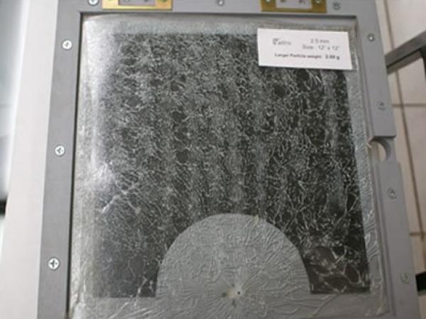
One of the most significant advantages of the RW tempering process appears to be in its application to “Thin” Glass. While conventional process approaches its limits at 3.0 and 2.9 mm glass the RW process appears to be capable of tempering glass down to 2.00 mm or less in thickness. 12 x 12 inch (300mmX300mm) glass panels of various thicknesses were tempered at the Vitro Central Glass Technology laboratory.

FIGURE 9
Some of the results are presented here. Fig 9 shows a photograph of the break pattern of 2.70 mm thick glass along with the maximum particle size. Similar pictures are shown in Fig 10, Fig 11, Fig 12, and Fig 13 of glass thicknesses down to 2.00 mm.

.jpg)
FIGURE 11
.jpg)
FIGURE 12

FIGURE 13
In conclusion, the proper means of exposing the pre-heated glass to a high flux density of controlled RW energy field allows very thin (< 2.00 mm) glass to be tempered. The ability to temper thin glass such as 2.0 mm or less is expected to have an enormous impact in the flat glass industry in terms of the need for raw material, energy consumption at the melting furnace, transportation density of glass panels, weight reduction of tempered window panels etc.
The very thin tempered glass is also expected to assist Photo Voltaic Cell industry in their quest for more durable and lighter panels with higher light transmission. Yet another area of application is in the fabrication of light laminated panels with very high impact resistance. The even more exciting part of this process is that it can be added on to most existing glass forming and tempering equipment.
Prem Boaz
Glass Products Consulting LLC
6674 Merryvale Lane
Port Orange, Fl., 32128
ptboaz@earthlink.net
Consulting for Vitro Group of Mexico