
Article Information
- Digital Object Identifier (DOI): 10.47982/cgc.8.435
- This article is part of the Challenging Glass Conference Proceedings, Volume 8, 2022, Belis, Bos & Louter (Eds.)
- Published by Challenging Glass, on behalf of the author(s), at Stichting OpenAccess Platforms
- This article is licensed under a Creative Commons Attribution 4.0 International License (CC BY 4.0)
- Copyright © 2022 with the author(s)
Authors:
- Barbara Foolen de Oliveira - TU Delft
- Arjen Veenstra - Octatube
- Maria Meizoso Aguilar - Octatube
- Mauro Overend - TU Delft

Abstract
From early 20th century architects have envisioned transparent buildings such as Mies van der Rohe’s “skin and bones” concept and his 1921 proposal for the Friedrichstrasse Skyscraper competition in Berlin. One hundred years on, there is a much better understanding of the energy consumption implications of highly glazed buildings, yet architects, developers and users are still attracted to fully transparent facades. This paper sheds some light on the challenges to build with high performing glazing façade systems (originally called curtain wall systems) while efficiently utilising resources and reducing its manufacturing embodied carbon.
This can be achieved by omitting the typical frame (mullions and transoms) and making the glass work structurally. Built examples by Octatube are Triodos Bank (Netherlands) and Echo Building (TU Delft- Netherlands). A further option that will focus on sustainable unitised systems is currently being explored by Octatube and TU Delft Building Technology graduation student. This is based on an optimised unitised frame integrated in between glazed units. These different systems will be assessed and compared against each other regarding its end-of-life recovery potential, embodied carbon and visual impact.
1. Introduction
1.1. Growth in demand
Glass was discovered around four thousand years ago. But it was not until the 1st century AD that it was used in architecture, for example, in window glass (Patterson 2011). Throughout the years glass had been used mainly for natural lighting whilst protecting from outdoor elements. This meant that the topic of the transparency of the windows had not yet been important until around the 18th century (Wigginton & Harris 2002).
Improvements in glass production and application gave way to a shift from an artisanal process to mass production (Eskilson 2018). Due to these changes, glass windows became more popular and available. At the beginning of the industrial revolution, the densification of cities was creating the need to build upwards. This set the perfect stage for new technological advancements of materials such as iron, steel, concrete, and glass to be widely implemented (Patterson 2011).
Through the years glass was widely popular for architectural use (Ascher-Barnstone 2003). This demand for glass is on a rising trajectory. The flat glass market is set to grow by approximately 1.3% of its current (2020) value by 2026 (Mordor Intelligence 2020).
1.2. Research definition
Throughout the years’ improvements were made to the glass facades to achieve high levels of transparency. This is particularly evident in curtain wall system, which are nowadays one of the most popular façade systems, especially for large commercial buildings. However, due to its protruding frame (mullions and transoms), it does not meet the users requirements of transparency.
Occasionally, the desired level of transparency can be achieved through a frame-less system, using structural glass. Nonetheless, this is not an ideal solution as it is an inefficient use of materials and time-consuming to design, produce and assemble. Which leads to a higher environmental impact and economic cost.
As can be seen from the growth of the curtain wall market, there is a demand for a more unitized facade system (Reports and Data 2019). Together with the demand for a highly transparent facade, there is therefore a gap in the market for fully transparent unitized facade systems.
This study aims to fill this gap by answering the following research question: How can a unitized facade system achieve a higher degree of transparency? To do this, various sub-questions where explored. This paper deals with two of the sub-questions that are essential for the development of such a system, namely: What is the relationship between shape of framing system and the structural efficiency of the façade system?; How does the proposed system compare, in terms of end-of-life sustainability, with recently built BREAM outstanding Triodos Bank in the Netherlands?
1.3. Previous research
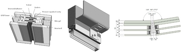
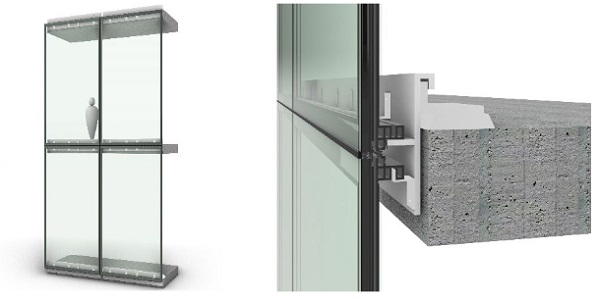
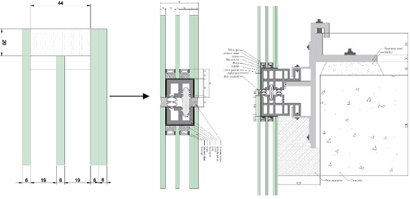
The proposed Slim Skins system, is based in previous research done by Cordero (2015). This research focused on improving the thermal transmittance of a curtain wall system. As can be seen in figure 2 on the left, Cordero (2015) proposes a frame integrated system where the mullion is sandwiched in between the glazing. This will not only allow for a lower thermal transmittance but also creates a far slimmer facade element. To achieve this system, the advantages of composite action were used.Composite action is a phenomenon that occurs when two building elements are interconnected with each other, increasing the structural properties of the element.
As studied by Cordero (2015), Pascual et al. (2019), Pascual & Overend (2021) and Pascual et al (2017) adhering the frame element of a façade to the glass, through structural adhesives, allow for a slimmer structure. Furthermore, these papers provide a detailed description of the mechanics of composite action between frame members and glass plates. The papers provide a very useful knowledge and scientific data, but they stop short of developing the system or assessing its environmental impact.
1.4. Reference projects
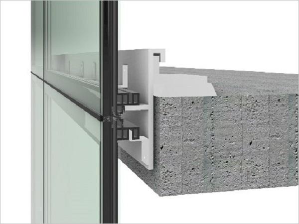
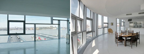
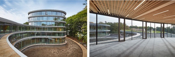
In addition to the previous research, a completed projectserved as a basis for inspiration, for this study. This is the façade of the Triodos Bank building (Figure 3) designed and installed by Octatube in 2017. This facade system has a one-way spanning glazing system, with supports along the top (ceiling) and bottom (floor) at each level, instead of a two-way spanning glazing often found in standard curtain wallsystems. By using this support system, the vertical framing members (mullions) that normally used in conventional curtain walls, are no longer needed, thereby achieving a very transparent facade. However, this system relies on the glass to span from floor to ceiling and therefore requires relatively thick glass to resist the applied out-of-plane loads (chiefly wind loads) safely and without excessive deflections.
1.5. What’s new
The proposed design combines the best of the two systems. The high transparency of the one-way spanning glazing and the economy of curtain wall system. As mentioned before previous research has not yet been developed further into a system ready to be used in practice. The latter is what this paper addresses directly with the system seen in figure 4. This means that al the limitations and tolerances set in place by building code and standard practices where met. Furthermore, this study for the proposed system provides a better insight into effects of profile shape on the composite action generated, which governs the structural efficient of the system. Additionally, the study provides an indication on the end-of-life environmental impact of the proposed and existing systems.
2. Methodology
The research was started by defining the problem through a literature review into the state of art of façade systems. Next a design scope and requirements, to which the design needs to satisfy, will be proposed according to the Dutch building code and further standard regulations used in the building environment.
Guided by the previous work, mentioned above, a set of façade performance requirements is established and a first design concept is created. Different variations on this design are introduced and assessed qualitatively and quantitatively. Starting with the structural feasibility assessment assisted byfinite element models (FEMs) of increasing complexity, validated by hand-calculations at the simpler stages. When the design variations are deemed to be structurally feasible and validated, they are developed further in terms of level of detail and materialization and the FEM is updated accordingly.
The FEMs of then used to assess the final design variants and the results obtained from each variant are compared to those obtained from the other variants and to the original performance requirements that were set at the beginning of the design process. The design variants are ranked according to the analysis and comparisons done in terms of structural, thermal, visual and process and the highest rank one is selected for a final round of design development, which ultimately leads to the completed ‘Slim Skin’ system.
Finally, the proposed system is once again assessed in terms of the original performance requirements and it is also evaluated in terms of its end-of-life sustainability. This latter is done by first, comparing different disposal scenarios and subsequently, by comparing the new Slim Skin system to the reference ‘Triodos Bank’ project.
3. Slim Skins system
Slim Skins is based on a frame integrated system that makes use of the composite action between the profile and the glass. As shown in figure 5, glass fibre reinforced polymer (GFRP) profiles are attached to the four edges of the glass panel. The GFRP profiles are similarly connected to each other in a similar manner to aluminium curtain wall systems. In this system however the corner connection element is also made of GFRP.
The performance requirements that the system should meet are divided into 4 topics: transparency, unitised system, maintenance, and design for practice which has in turn 5 sub requirements.
Regarding the transparency this system achieves the goal of flush construction with no protrusions from eth surface of the glass, and a minimum width of opaque materials visible through the glass. With these in place the construction creates a visually unobtrusive unitised system. The unitised aspect is accomplished by the embedded profiles. The panel can therefore be assembled in the factory by inserting and adhesively bonding the mullions between the glass of an insulated (triple) glazed unit. With the mullion and transom profiles embedded in the glazing unit, the gaskets and toggles are added and the panels are transport to the building site. Each panel is assembled by attaching it to the slab edges of the building, where the bottom is supported vertically and laterally (i.e. out of plane), while the top is restrained laterally. This process can be repeated along the building to ease the building process. Furthermore, the bottom-supported system also satisfies the ease of installation requirement and ease of removal / replacement of the panels for replacement or maintenance as it is.
The fourth requirement is design for practice which makes sure the system can be built. For this the structural aspects (deflection and stress) needs to be within the allowable limits. There is also a need for movement between the panels, which in this case is +/- 5mm. Furthermore, the tolerances were considered as the panel can move left to right and back and forth through the L bracket. For the up and down movement, the T bracket can be used. To ensure safety a fire barrier is placed to prevent spreading of a fire in between floors through the façade and an extra laminated glass panel was usedto ensure user safety by preventing a fall. In terms of thermal comfort, the system uses triple glazing. Lastly the weather sealant on the inside and outside make the façade system impermeable.
4. Structural assessment
4.1. Goal
With this first structural assessment the aim is to explore various design options (variants) with different sizes and shapes to determine which mullion designs are structurally feasible. This means that each design needs to satisfy the deflection and stress requirements set. Additionally, this assessment will give a better understanding of the composite action relation to its shape and contact surfaces.
4.2. Method
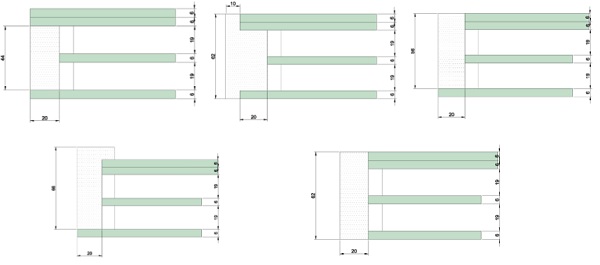
The first step in this assessment is to create feasible variations of the first detail draft. These different profiles can be seen in figure 6. Profile 1 is also known as the first detail draft on which these variations were based. With these profile variations defined, the calculations regarding the structural feasibility of each profile can be determined. Two principal aspects must be considered in the structural feasibility: stiffness and strength. As the allowable deflection (∆), the length of the embedded mullionprofile (L), and the wind load (w) are known, the minimum required bending stiffness (EI) can be calculated from:

From the minimum required stiffness (EI) and the second moment of area (I) of each profile, the minimum stiffness (E=Young’s Modulus) can be calculated.
The second structural aspect to consider is the strength required to withstand the applied forces. This is done by determining the maximum stresses occurring in the beam. On this panel, the profile will need to withstand the wind load and the self-weight of the panel itself. This creates three stresses: bending stress, axial stress, and shear stress. These values provide the threshold strength required. Together with the values obtained for minimum required stiffness they constitute the structural feasibility checks for each profile variant.
4.3. Results
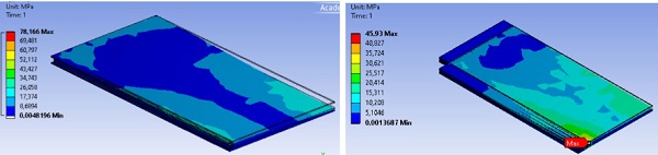
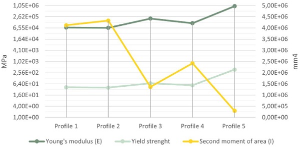
The results of hand calculations together with the finite element model (figure 7) are summarised infigure 8. Shear lag effects are considered in both the calculation and the models. The adhesive used in the model is EC-2216 B/A with the shear modulus properties defined by Overend et al. (2011) and the yield strength as stated by 3M (2009). In the graph, it is quite clear how the second moment of area influences the minimum required young’s modulus (E) and yield strength. The bigger the profile, the less is required in terms of structure.
Here the amount of composite action also has an influence, as the more contact the mullion has with the glass the less it needs to be strong and stiff. The highest amount of composite action can be observed in profile 2, as it has the highest second moment of area (I). In this case profile 2 can be considered as using 100% of its composite action abilities. Compared to this profile 1 benefits 95% from its composite action. Profile 3 and 4 use 31% and 56% accordingly. Lastly, profile 5 performs quite bad in terms of composite action as it only uses 7%.
To be structurally feasible, the profiles need to be within the following requirements. For the first four profiles the glass contributes at least 60% to the second moment of area of the panel. The young’s modulus of glass is known to be 69 GPa therefore, to achieve a deflection that is within the allowable, the minimum stiffness needed in profile 1-4 should not exceed that value of 69 GPa as the glass would fail otherwise. Note that for these calculations the modular ratio was not used as the influence on the results are negligible because the profile is a very small part of the section. For profile 5 the mullion does most of the work and thus the young’s modulus should not exceed that of the possible materials for the mullion. None of these profiles met these requirements, therefore changes were made to thickness of the glass, for profile 1 to 4, and changes were made to the mullions width in profile 5.
5. Sustainability assessment
5.1 Goal
The last step of this research was looking at the environmental impact of the Slim Skins façade system at its end-of-life. This will give a greater understanding on how this facade panel performs in terms of sustainability compared to the existing market. Furthermore, the assessment can highlight where improvements could be made to better its impact on the environment.
5.2. Method
In this study the sustainability assessment follows the method developed by Hartwell & Overend (2019). With this method not only can the sustainability performance of the different facades be compared to each other but also in terms of the different end-of-life (EoL) scenarios possible. The method provides a process-based life-cycle impact assessment which demonstrates the impact that different new or existing facade systems and EoL routes have on the environment in terms of embodied energy (EE) and carbon emissions also called global warming potential (GWP).
The first step is to establish what the facade panel is made of and how it is made. Next it is important to know what the end-of-life of each material is for each scenario. In scenario 1 the façade ends in landfill. Scenario 2 is focused on recycling, including downcycling and energy recovery. These scenarios are the most likely nowadays. Scenarios 3 and 4 are about reuse of the components and the system entirely, respectively. Now the environment impact can be calculated by looking at the EE and GWP saved (negative value) and needed (positive value) with the following formula:
![]()
5.3. Scope
For this study, only ERecovery will be considered. ETransport was not considered as the project location where the Slim Skins facade system will be placed is unknown and thus cannot be compared to that of the Triodos Bank. Furthermore, the EEndlife was not assessed because not all of the data was available making the inventory incomplete for this aspect. Additionally, the service life and performance degradation of the facade due to ageing was considered as it is beyond the scope of this study.
For the evaluation of the Slim Skins facade system, one panel of 2x4 meters was used. Here the connection elements to the floor and the fire insulation were not taken into consideration to simplify the assessment. Regarding the facade system of the Triodos Bank a panel of 2.9x3.2 was considered.As the panel size between the two systems differs it was chosen to analyzed the environmental impact per m². The materials embodied energy and CO2-equivilant data was gathered by using CES EduPack software (2021) where the average of the value range was used.
5.4. Results
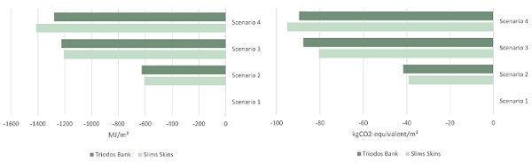
When looking at the different EoL scenarios it can be observed that scenario 4 has the most environmental savings, regardless of which of the two facade panels is assessed (figure 9). This scenario is thus considered the baseline to which other scenarios can be compared. This means that scenario 4 can be assumed being 100% fully re-use potential (FRP). The approach of scenario 3 scores the best with an average FRP of 95.9% and 97.1% in terms of EE and GWP accordingly. The next best EoL route is scenario 2 which exploits the FRP to an average of 55.1% and 51.3% in terms of EE and GWP accordingly.
Last is scenario 1 which does not have any environmental savings as all the material goes directly to the landfill. From the study done by Hartwell & Overend (2019), it can be observed that if ETransport and EEndlife (equation 2) would also be considered, the order of best to worst scenario remains the same. However, the value is significantly lower for scenario 2 due to the impact of the recycling processes.
The results of the study can be seen in figure 9 where a clear difference between Triodos Bank and Slim Skins could be observed. This difference is situated in scenario 4 where the whole system is reused elsewhere. This can be attributed to not having to cut and discard a part of the glass like in scenario 3, as it does not need to be separated from the other elements.
6. Discussion
6.1. Structural assessment
As was seen in the results changes where needed to make the profiles structurally feasible. In the first four profiles, the most efficient way to improve this is by using thicker glass panels. For profiles number 1 and 2 the increase in thickness was of maximum 4 mm, so that profile 1 has a total thickness of 62mm and profile 2 of 64mm. In profiles 3, originally 62mm thick, and 4, originally 72mm thick, an increase was needed of 28mm and 16mm accordingly. Lastly for profile 5 the mullion needs to be wider, changing from 20mm to almost 100mm.
When looking at the composite action between the glass panels and the mullion it could be stated that the extra set of wings (small extrusions on the sides of rectangular mullion) increased the amount of composite action.
6.2. Sustainability assessment
From these results, scenarios 3 and 4 are the best option as it has an increased environmental savings of at least 1.8 times higher in terms of EE and 1.9 in terms of GWP compared to scenario 2. When taking the environmental impact of transport and end-of-life process into account, it is expected that the benefit of re-use will be even higher.
Nowadays the most common EoL route is scenario 2: recycling. However, from the assessmentperformed in this study, it is evident that re-use (scenario 3 and 4) is more beneficial and thus new designs should allow for such EoL scenarios.
7. Conclusion
7.1. Structural assessment
For the remaining of the assessments in this study profiles 3 and 4 were deemed not suitable for the panel design as producing glass panels above 12 mm thickness are expensive or not even produced when passing the thickness of 25mm. Furthermore, profile 5 and 2 were later on excluded as an option on the basis of a visual assessment.
Another aspect that is studied in this assessment was the relationship between shape of the profile and composite action. From this study it was determined that the amount of contact surfaces is related to the amount of composite action in place. So, the more contact surfaces the higher the composite action is and the more the structural properties of the glass are put to good used.
7.2. Sustainability assessment
Both facade systems perform at similar levels in terms of end-of-life environmental impact. However, in scenario 4, it should be considered that dismantling all the elements and building it up again at another site could cause issues such as damage or loss of parts. So, in that case Slims Skins has a small advantage of being a unitized system and thus ensuring an easy relocation.
7.3. Overall
To achieve such high transparency in a unitized system, the concept of composite action was used. This enabled smaller profile dimensions, because the glass makes significant contribution to the stiffness of the panel. The design was evaluated to determine if it would be viable to use it in practice. In theory, it satisfies all the objectives and most of the requirements.
With the final design proposed to answer the research question, there were some challenges. The design is quite intricate in terms of its profile. Considering this together with the size of the panel itself, complications can be expected while building as a high precision is required even if the tolerances are considered.
Another challenge is the amount of adhesive used. This has a negative effect on the end-of-life of the panel as it can be hard to remove and disassemble all the elements for recycling or reuse. However, for the reuse of the complete system, it does provide an easier transfer process from and to the new building site.
Acknowledgements
A special thanks goes to Rebecca Hartwell for guiding me through the sustainability of a facade panel at its end-of-life, as this topic can easily be overwhelming due to the extensive aspects that can be considered.
References
3M. (2009, June). Product Data Sheet -Epoxy Adhesive EC-2216 B/A.
Ascher-Barnstone, D.: Transparency. Journal of Architectural Education, 56:4, 3-5 (2003).
CES EduPack software: Cambridge, UK: Granta Design Limited (2021).
Cordero, B.: Unitised curtain wall with low thermal transmittance frame integrated within the insulating glass unit though structural adhesives. Escuela Tecnica Superior de Architectura (2015).
Eskilson, S. J.: The Age of Glass. London: Bloomsbury Academic (2018).
Front Inc.: 100 11th Avenue (2010). https://www.Frontinc.Com/Project/100-11th-Avenue/.
Hartwell, R., Overend, M.: Unlocking the Re-use Potential of Glass Façade Systems. GPD Glass Performance Days (2019).
Mordor Intelligence: Flat Glass Market - Growth, Trends, COVID-19 Impact, and Forecasts (2021 - 2026). Mordor Intelligence (2020).. https://www.mordorintelligence.com/industry-reports/flat-glass-market#faqs
Octatube.: Detail 06 - Bovenconsole verdieping. In Triodos de Reehorst Driebergen - Zeist(2017).
Overend, M., Jin, Q., Watson, J.: The selection and performance of adhesives for a steel–glass connection. International Journal of Adhesion and Adhesives, 31(7), 587–597 (2011). https://doi.org/10.1016/j.ijadhadh.2011.06.001
Pascual C., Montali J., Overend M.: Adhesively-bonded GFRP-gl ass sandwich components for structurally efficient glazing applications, Composite Structures, Volume 160, 15 January 2017, Pages 560-573 (2017)..
Pascual, C., Nhamoinesu, S., Overend, M.: The flexural response of large scale steel-framed composite glazing panels. Glass Struct Eng (2019).
Pascual C., Overend M.: Buckling of sandwich struts with a particular application in composite multi-layer glazing, 2021, Engineering Structures (2021).
Patterson, M.: Structural Glass Façades and Enclosures: A Vocabulary of Transparency. New Jersey: John Wiley and Sons Ltd(2011).
Reports and Data: Glass Curtain Wall Market To Reach USD 89.03 Billion By 2026 (2019).
Wigginton, M., Harris, J.: Intelligent skins. Oxford: Butterworth-Heinemann (2002).


