Source:
Challenging Glass 6
Conference on Architectural and Structural Applications of Glass
Louter, Bos, Belis, Veer, Nijsse (Eds.), Delft University of Technology, May 2018.
Copyright © with the authors. All rights reserved.
ISBN 978-94-6366-044-0, https://doi.org/10.7480/cgc.6.2115
Author:
Marcin Brzezicki - Faculty of Architecture, Wroclaw University of Science and Technology
Serrated facades substantially influence the building’s tectonics understood as the relationship between the structural and the artistic form. They also have a major impact both on building physics (increased surface of heat exchange compared to flat facades, solar avoidance – decreased solar gains if properly designed) and on visual appeal. This article examines façade morphology and analyzes the influence of its geometry on the aesthetic quality of the envelope.
The morphological analysis includes the serration angle between the wings (acute or obtuse), wing proportions, and façade depth. An exceptional feature of serrated façades is that the optical phenomena on the façade change depending on the viewing angle. This paper discusses various perceptual zones that produce different phenomena, e.g.: (i) single wing visibility, (ii) mutual wing self-reflection, (iii) primary and secondary virtual The presented paper is based on case studies with special attention to morphological and qualitative analysis. Cases serve as visual (photographs) and graphical illustrations(diagrammatic drawings). The paper also includes a brief presentation of selected recently completed case studies.
1.Introduction
Serrated glazed building envelopes are a very eye-catching element of contemporary architecture. The serration of the façade has a significant influence on the reception of the building’s volume as it modifies its tectonics, i.e. provides sculptural depth to the façade. This depth makes the façade more attractive visually, but also alters its technical parameters by increasing the total surface of the façade, which, in turn, may result in potential heat loss/gain problems.. The main optical properties of serrated facades are the result of their geometry. According to (4, p. 28) serrated facades belong to a group of modified planar vertical and horizontal facades whose visual characteristics deserve to be studied in detail.
2.Serrated façade geometry
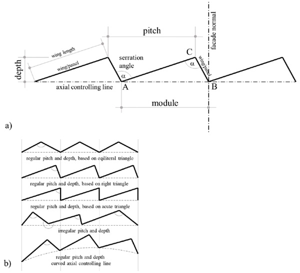
A serrated façade resembles the edges of a serrated blade, hence the name. This architectural solution is also commonly known as “tilted windows”, “zigzagged” (Administration building..., 2011) “folded” or even “pleated” facades. The geometry of the serration is discussed below on the basis of a diagram (see Fig. 1). Because of the fact that the serration of a saw blade represents a well-documented reference to the serration of the façade, some of the definitions used in this paper are borrowed from the field of mechanical engineering. A façade is usually constructed along a linear (straight) or curved axial controlling line. The dimension of the façade (i.e. the distance between points A and B) is the “pitch” or “module”. The length of a perpendicular from C to the base containing A is the “depth” of the façade. The angle at point A (α) is the “angle of serration”. In repetitive solutions the angles at point A and point C (α) are usually of the same degree measure. The serrated façade panels will be referred to as “panels/wings”. The panels/wings can be equilateral or have different lengths.
The serration can be applied in plan (horizontally), in section (vertically) or in both directions/axes. “Intersecting edges and, in particular, »corners«, at which three surfaces coincide, require special attention” (Herzog, 2008, p 28). The simplest and most frequently observed solution is the serration in plan, which requires only vertical joints between the neighboring panels. A vertical joint functions as a proper seal between the neighboring panels/wings and is easier to develop from a technological point of view because it resembles a standard right angle façade corner connection (which is a standard solution).
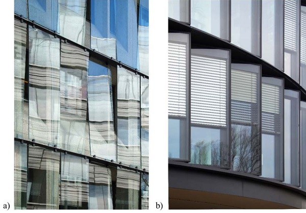
The serration in vertical section is also an option, but requires a water-tight horizontal seal and proper runoff management (gutters and downpipes). Therefore, in terms of technology, such a solution is much more demanding and less popular. For instance, the Casuariestraat, DGMR in Hague (arch. Fokkema Partners, 2007) features only the serration of the external envelope which does not require a proper water-tight seal and heat flow management (see Fig 2a). A water and heat management solution is necessary if the serration of the façade is designed in both directions. This paper only focuses on the serration in plan.
Serration can be applied to planar and curved facades (along a straight or curved axial controlling line). In the first case the serration usually includes a repetitive module but variable pitch is also possible. In the case of curved façades the serration usually follows the curvature of the building while the prefabricated elements of the façade are usually repetitive and connected by articulated vertical joints. This solution allows for adequate angle tolerance.
A serrated envelope usually serves as the thermal façade of the building but can also function as the external layer of a double-leaf envelope, in which case it has single glazing – e.g. KfW banking group office tower in Frankfurt am Main, (arch. Sauerbruch Hutton, 2010) or the ESO European Southern Observatory (arch. Auer Weber, 2008) – see Fig 2b. In the majority of cases the serrated façade is fixed to the loadbearing structure of the building at the slab level.
3.Visual impact
One of the most important factors in glass facades are the optical parameters of the light-transmitting parts of the envelope. “Every transparent material with surface, smooth enough to let the light through without deflection, simultaneously reflects light, due to its physical properties on the micro-level” (Brzezicki, 2014). This results in many perceptual phenomena which are caused by reflected light and depend on the viewing angle. When glass is looked at perpendicularly, i.e. at an angle of 0° measured from the line perpendicular to the surface of the glass, it is mostly perceived as transparent. This viewing angle shall be referred to as “normal angle”. As the viewing angle increases the reflection grows and “increases dramatically above 70°, to almost 100% reflection at glancing angle” (Wiggington, 2002, p. 71).
Due to the fact that the smooth glass surface can produce mirror reflections, serrated glass façades should be considered, from the optical perspective, as optical systems comprising two adjoined mirrors (sharing one edge and inclined). In this type of façade two planar mirrors M1 and M2 (glazed wings/panels) are attached to each other at a specific angle. There are two key parameters that influencing the visual impact of the serrated façade: (i)the observer’s position and (ii) the serration angle α. Both parameters result in optical/perceptual phenomena that include: single wing visibility, self-reflection of façade wings, fragmented reflection of the surroundings and increased number of virtual images. These phenomena will be further referred to as:
- Observer position dependent phenomena,
- Serration angle dependent phenomena.
4.Observer position dependent phenomena
4.1.Single-wing visibility
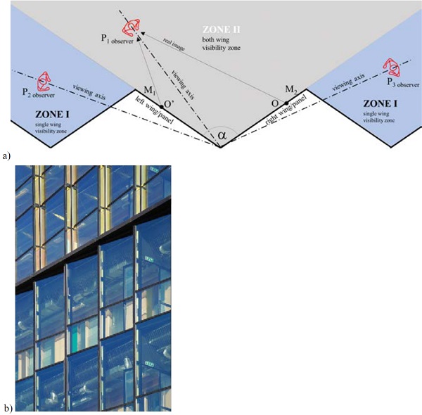
The most evident phenomenon that solely depends on the position of the viewer is the visibility of the single façade wing/panel. This is probably the most important visual consequence of using glazed or any other types of serrated facades. The “visibility field” in front of the façade can be divided into two “perceptual zones”, which are depicted on the diagram in Fig. 3. Mirrors M1 and M2 constitute the façade wings whereas P1, P2 and P3 are the façade observers. In the analyzed case the serration angle α equals 114°. In zone II both wings are visible, while in each zone I only one wing is visible. Visibility in zone II works for all viewpoints inside the serration angle e.g. for observer P1, while the other zone covers all viewpoints located outside the serration angle α e.g. for observers P2 and P3 on Fig. 3.
4.2.Perception of rhythm and proportions of a façade
For all viewpoints located in zone I (outside the serration angle α) only a single façade wing will be visible. If the serration of the façade is based on an equilateral triangle, the perception of the façade’s rhythm will be similar viewed from two non-perpendicular angles that are located in zone I symmetrically to the normal angle, e.g. as in the case of observers P2 and P3 in Fig. 3. However, if the façade wings are not identical, the observer’s position substantially influences the perception of the building because of the different proportions of the visible façade wings/panels (width/height relation in 3D), e.g. the thinner wings create a different façade rhythm than the thicker ones.
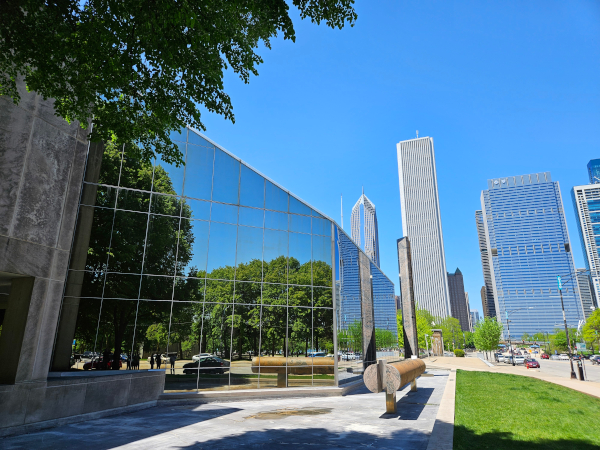
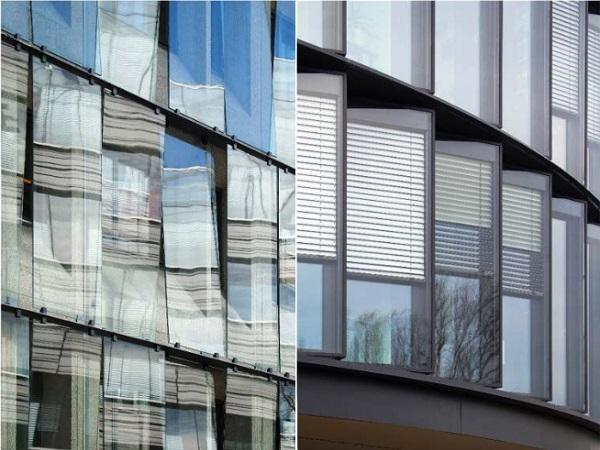
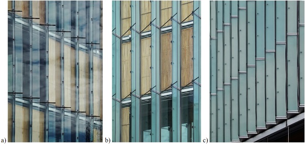
The different/variable proportions of the wings can be intentionally used by the designer to differentiate the possible visual impact of the building. Fig 3a shows the diagram of perceptual zones, while Fig 3b depicts the façade of Conservatorium of Amsterdam (arch. Frits van Dongen, 2007) which illustrates how façade proportions change when the direction of its serration changes on adjacent floors. Fig 4 shows the difference in the serrated façade’s appearance depending on the viewing angle based on Oskar von Miller Forum (arch. Herzog + Partner, 2009).
4.3.Self-reflection of façade wings/panels
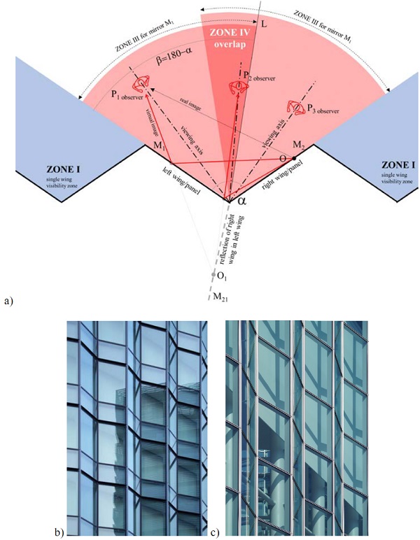
Simply put, the self-reflection (mutual reflection) of the façade wings is the reflection of one wing in the other wing. This phenomenon depends on the position of the observer. Visibility zone IIIis created within zone II which allows the observers to see the reflection of one wing/panel (e.g. M2) in the other wing (e.g. M1) and is defined by the plane of the mirror (e.g. M1) and the plane L adjoined to M1 at an angle of β = 180°– α. Observers P1 and P2 located within zone IIIfor the left wing/mirror M1 can see the reflection of the right wing M2 in the left wing M1 (in fact they see the reflection of point O located directly on the wing M2), while observer P3 located outside this zone cannot see this reflection.
The same applies to the other wing. These two zones IIIon both wings overlap to create zone IV in which reflections of both wings are visible in both wings. Observer P2 can see the reflection of the left wing in the right wing and vice versa. This self-reflection can be observed in the case of Fuji Xerox R&D Square building (arch. Shimizu Corporation, 2010) and Fuji Television Wangan Studio in Tokyo (arch. Kajima Design, 2010). Fig 5a illustrates the self-reflection of the façade wing, the case studies are pictured on the Fig 5b and 5c. This phenomenon depends on the position of the observer, which is explicitly visible in the perspective projection.
4.4.Fragmented surrounding
From the optical perspective serrated façades function like mirrors and reflect the fragments/elements of the townscape or landscape surrounding the building/façade. In the case of continuous glass facades the reflection of the surroundings is also continuous. On the other hand, in the case of serrated facades, the reflection of the surroundings is fragmented and one reflection alternates with the other. This produces an interesting visual effect, especially in visually diversified environments, in which the reflection alternates between different elements (e.g. the images of an architectural monument and contemporary architecture). Serrated facades are often observed dynamically by observers in motion. This means that all the factors that influence the self-reflection phenomenon change gradually, which in turn causes changeability/variability of the final visual effect.
5.Serration angle dependent phenomena
A brief geometrical analysis shows that all serration angle dependent phenomena are visible only in zone II (which is divided into zone III and zone IV). Virtual images of an object O located between two adjoined mirrors of an optical system require a more detailed geometrical analysis. One mirror produces one virtual image (defined as the primary virtual image) while two perpendicular mirrors produce three virtual images (of which two are defined as primary virtual images and one is defined as the secondary virtual image because it is the reflection of a reflection), see Fig 6a and 6b.
“One observes that as the angle between the mirrors decreases, the number of images that can be seen increases” (Other multiple Mirror Systems, 2018) up to an infinite number of images when the mirrors are parallel. In the context of serrated facades the number of virtual images that are created depending on the serration angle α can be calculated based on the formula N = (360°/α) – 1 (the number of images is rounded to the nearest integer).
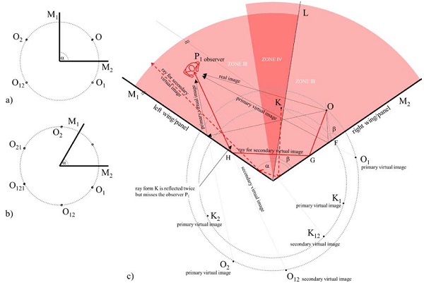
Based on the geometrical analysis depicted in Fig 6c the necessary condition for observer P1 to see the secondary virtual image O12 of the object O is a double reflection – a ray (red continuous line) must travel from object O and bounce off mirror M2 (right façade wing) at point G and then from mirror M1 (left façade wing) at point H. In order for observer P1 to see the secondary virtual image, the rays traveling from object O must be reflected by both mirrors before reaching the observer. If the ray is only reflected once, observer P1 will only see the primary virtual image (a simple single reflection).
From the above analysis it is evident that the secondary virtual image is visible for P1 for all objects located within the two zones III, whereas it is invisible for objects located in zone IV. Observer P1 cannot see the secondary virtual image K12 of an object K located in zone IV. A ray (red dotted line) travelling from K is reflected twice, i.e. first by mirror M1 and then by mirror M2, but it misses observer P1. As was observed in the previous sub-chapter this zone is defined as the area/space between the plane of mirror M1 and plane L that is at an angle of β = 180°– α to this mirror. The same, but symmetrical, zones and relationships apply to mirror M2. These two zones IIIoverlap to create zone IV, which corresponds to zone IV identified in the previous sub-chapter. Zone IV allows for the visibility of only primary virtual reflections of objects located within this zone.
If the serration angle decreases the number of virtual images increases according to the formula N = (360°/α) – 1. Due to the fact that the serration angle in the studied cases is never smaller than 90° it is recommended to refer to the study by Derfel (2015) for such rare cases.
6.Conclusion/discussion
The explanation of optical phenomena associated with glazed serrated facades is found in the fact that the wings of those facades function as mirrors in an optical system. To sum up there are 3 specific zones that determine the visual perception of serrated facades. In Zone I only a single wing is visible, whereas in zone II both wings are visible, including mutual reflections. Zone II can be further divided into two zones, i.e. zone IV in which only the primary virtual reflection is visible, and zone IIIin which both primary and secondary virtual reflections are visible to the observer. In general it can be stated that “the number of images created/visible depends not only on the angle between the mirrors, but also on the position of the object” (Wiggington, 2002) and should therefore be taken into account when designing the geometric definition of the serrated façade.
Serrated facades are a great potential for the industry of glass façade engineering with an abundance of interesting optical phenomena that can be produced. Since the visual outcome depends on the façade’s geometrical parameters (pitch, serration angle, wing length and depth) the morphology of the façade should be extensively studied with the application of descriptive geometry (representation of three-dimensional objects in two dimensions) and computer-aided simulations. The number of reflections necessitates the extensive use of the software’s ray tracing options to obtain credible visual results.
Acknowledgements
The collection of the data for this paper was funded by the Polish National Science Centre grant entitled: “New trends in architecture of transparent facades – formal experiments, technological innovations”, ref. no. 2014/15/B/ST8/00191. The participation in the conference is was funded by the Ministry of Science and Higher Education, Poland, grant, ref. no. S70401-0082-17-K0106.
References
Administration building in Frankfurt, Detail Green. 1, 26–35 (2011)
Brzezicki, M.: The pictorial analysis of the transparent panes: the balance between the reflected andtransmitted image. In: Nikolić, S., Meštrić, V., Peteh, I., Rastija, V. (eds.), CroArtScia 2-11: Symmetry: Art & Science, pp. 43–46, The Croatian Academy of Sciences and Arts (2014)
Derfel, G.: Odbicia w dwóch zwierciadłach (Reflections in Two Mirrors) University of Warsaw, Institute of Mathematics http://www.deltami.edu.pl/temat/matematyka/geometria/2015/08/28/1509delta-lustra.pdf (2015) Accessed 10 January 2018
Herzog, T.: Façade Construction Manual, Birkhäuser Architecture (2008)
Conservatorium of Amsterdam; https://vd-k.eu/conservatorium-van-amsterdam-amsterdam/ (2007) Accessed 10 January 2018
Other Multiple Mirror Systems, Physics Classroom, http://www.physicsclassroom.com/class/refln/Lesson-2/Other-Multiple-Mirror-Systems (2018) Accessed 10 January 2018
Wiggington, M.: Glass in Architecture. Phaidon Press (2002)