

Challenging Glass 3 – Conference on Architectural and Structural Applications of Glass,
Bos, Louter, Nijsse, Veer (Eds.), TU Delft, June 2012.
Authors:
Luís Martins, Raimundo Delgado
Faculty of Engineering of the University of Porto, Portugal, www.fe.up.pt
Rui Camposinhos
Scholl of Engineering of Polytechnic of Porto, Portugal, www.isep.ipp.pt
Tiago Silva
FACAL - Façade Engineering, Portugal, www.facal.pt
Due to its transparency today’s architectures often rely on glazed façade solutions to execute the building envelope. During a seismic event, glass breakage and fall out can occur and threaten occupants and passers. So in earthquake prone regions this must be accounted in the design project; however, there is little research on the behaviour of glazed façades under seismic loads.
This papers focus on the results of a project under development to ascertain right well dimensioned and adequate solutions to glass facades using point fixing systems under seismic or wind actions. Numerical analyses were performed, using finite element commercial software, the results are compared with simplified methods and conclusion are drawn.
Keywords: spider glass, glass façade seismic behaviour, curtain wall glass façade
1. Introduction
Recent developments in science and technology allowed glass to be used in several structural demanding applications such as façades, roofs, girders and columns, etc. Due to glass’ brittle behaviour this calls for more refined analysis methods and greater design detailing to ensure structural stability and safety. Currently modern facade buildings rely on glazed curtain wall systems. These systems include either singular aluminium alloy frame glass curtain walls or frameless glass curtain walls. This is the case of the so called spider fixing systems, which are pointed supported.
Although there are some research on the behaviour of glass panels under out-of-plane loads, e.g., wind loads, the combine effect of both in-plane and out-of plane loads that are applied to the panels in an earthquake is a field of research still on its early stages. In fact, seismic action brings out specific problems to designers, due to the lack of, at least well-known, international rules or regulations about this problem. The scope of this paper is to present the relevant aspects of the seismic loading in point fixed glass panels. Firstly a simplified method based upon the elastic response spectrum is introduced, then the results of a time history dynamic analyses are presented.
2. Seismic design of glass façades
Earthquakes cause damage to the building main structure as well as to the non-structural components. Falling façade fragments during an earthquake poses a serious hazard to pedestrians and occupants as well, so in earthquake prone regions its must be accounted in the design.
Sucuoǧlu and Vallabhan refer broken window glass as the second most serious nonstructural damage, for example in the 1985 Mexico City earthquake over 50% of the 263 office observed buildings had experienced some sort of glass breakage [1]. During an earthquake two types of lateral loads are considered acting in the façade panels: the “in plane” loads and the “out of plane” loads. Both inertial loads are caused by the horizontal displacements of the building’s floors, yet the in-plane actions causes, mainly shear stresses, and the others give rise to extra inertial forces due to the panel’s bending.
The frequency content of the dynamic loads transmitted to the panels is modulated by the building natural frequency, so if it happens that it has a value very close to the panel’s natural frequency, resonant effects occur with an agonisingly increase of the dynamic response, a well-known phenomena that must be avoided, otherwise structural safety may be compromised.
As there are no design regulations for determine seismic loads in glass façades, a laboratory test procedure according the American Architectural Manufacturers Association recommendations [2, 3] is followed in order to evaluate the maximum seismic drift which may cause glass breakage and fall out of framed glass panels.
The dynamic test procedure considers a sinusoidal drift history for the procedure testing with growing amplitudes to a maximum of 150 millimetres (Figure 1). This test method has been applied in previous studies, like (Memari et al) [4], and is going to be used to assess the seismic behaviour of point fixed glass panels in the Seismic Laboratory of the University of Porto Engineering faculty.
.jpg)
Click to enlarge. - Figure 1: Schematic of displacement time history for dynamic crescendo test [2].
3. Simplified method to assess the seismic forces
The simplified method to assess the seismic forces transmitted to the façade panels, was adapted by Camposinhos [5] from the work of Singh [6, 7], and is based on the response spectra of Eurocode 8 (EC8) [8]. Figure 2 presents the elastic response spectrum adopted in this work.
Response spectrum (Seismic action type II; soil type D; seismic region 2.1; η=1.0)
.jpg)
Click to enlarge. - Figure 2: Response spectrum [8].
Thus the dynamic load transmitted to the façade panels (equation 1) depends on the building’s natural vibration period and on the panel’s mass and natural vibration period.
.jpg) (1)
(1)
where,
FEk characteristic seismic force;
CfZ seismic coefficient of the panel (depends on the building dynamic
characteristics and the position on the panel in the building);
SDS ground acceleration value;
γE importance coefficients of the panel (ranging between 1.0 and 1.5);
ME panel’s mass;
RE coefficient of performance of the panel (ranging between 1.5 and 3.5).
Prior to the application of the simplified method a parametric analysis was made to evaluate the variation of seismic coefficient CfZ with the dynamic properties of the panel and its position or height in the building. Two different cases were studied: in the first case the panel is assumed to be in the last floor (m=N), and in the second, the panel was assumed to be in placed at the penultimate floor (m=N-1). Figure 3 and Figure 4 presents the variation of Cfz with the natural period of vibration of the building for different values of the natural period of vibration for the glass panel.
Variation of CfZ (m=N; ξ=5%)
.jpg)
Click to enlarge. - Figure 3: Variation of Cfz (m=N).
Variation of CfZ (m=N-1; ξ=5%)
.jpg)
Click to enlarge. - Figure 4: Variation of Cfz (m=N-1).
The results (Figure 3 and Figure 4) shows a very significant resonant effect for low periods and a comparison between them allow to conclude that a panel in the last floor corresponds to the most severe situation in what seismic excitation concern, with values about 40% higher, once the coefficient, CfZ is directly correlated with the maximum seismic force acting in the panel.
4. Case study
4.1. Field application
In order to analyze the behaviour of different solutions of point supported glass panels systems under seismic loads a partnership study involving the Faculty of Engineering of the University of Porto and FACAL – Façade Engineering, a Portuguese company known for its work in the field of glazed façades, has been promoted.
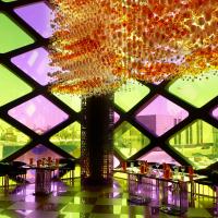
FACAL has a great experience in technical innovative solutions, namely looking for the development and easy installing thinner and lighter glazing, and is well known by the execution of famous facade glazings such as the glass system in Casa da Música in Oporto, the double skin façade Torre H in Lisbon, the glazing of the Spanish Pavilion in the International Fair in Zaragoza or the glass roof of the Metro Station at Sá Carneiro Airport in Porto.
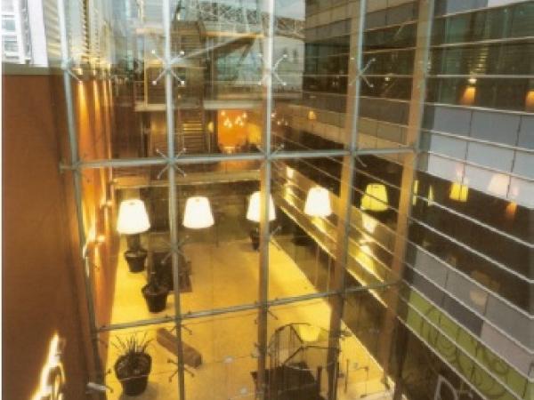
On the basis of this work is the newly-built office building of Bouygues Imobiliária in Lisbon. A particular attention was given to the safety requirements of a 20 meters high point-supported glass façade over the main entrance of the building. The post-breakage behaviour of the laminated safety glass panels is the primary concern. This is often a neglected problem in glass façades yet of greater importance since Lisbon as many other metropolis is prone to seismic activity.
A crucial concern on this matter is essential: The integrity of the glass façade must be preserved and assured that there’s no risk of glass fragments fallings.
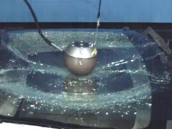
Among the various enhancement solutions the use of laminated safety glass with the DuPont interlayer SentryGlas® provides an optimal behaviour due to its excellent postbreakage performance with the glass fragments remaining adhered to the interlayer, without falling down.
.jpg)
Figure 5: Point-supported glass façade - office building of Bouygues Imobiliária in Lisbon.
4.2. Geometrical and mechanical properties
This paper focus on a set of five point supported laminated glass panels. All the specimens have a surface of 2350x2300 mm2 differing on the glass thicknesses, the interlayer and distance from edges to holes (Figure 6).
.jpg)
Click to enlarge. - Figure 6: Geometrical configuration of the glass panels: left) V1 and V2; right) V3, V4 and V5 (Drawings by: FACAL).
The panels identified as V1, V2, V3 and V4 are obtained from 10mm strengthened glass and a 1.52mm thick interlayer together with a 8mm also tempered glass. Panel V5 is made from two 12mm tempered glass sheets.
Panels V1 and V3 have a SentryGlas® film while the remaining panels have PVB interlayer. Furthermore a panel with the same geometrical configuration of that of V5 but with SentryGlas® interlayer film was additional considered in the analyses.
The properties of the PVB's Young modulus ranges from 3.2 MPa to 18 MPa [9, 10], so in the panels with this type of interlayer three different values for this parameter were considered: (i) 3.2 MPa, (ii) 9.0 MPa and (iii) 18.0 MPa. In the case of SentryGlas® the value of 300 MPa was adopted for its Young modulus, as suggested by Delincé [10].
Table 1 summarises the relevant data for the studied glass panels.
Table 1: Test specimen's description.
.jpg)
Click to enlarge.
Seismic Behavior of Point Supported Glass Panels
![]()
Click to enlarge.
4.3. FE model
To evaluate the structural response of the glass panels a set of numerical models were made using commercial finite element (FE) software.
The glass panels and interlayer film were modelled with 8-node 3D finite elements. In the interior of the panel the maximum size of the finite elements was limited to 2 centimetres, while near the supports the maximum size was reduced to half to attend the stress concentrations near the holes to take in account the expected stress concentrations in this regions.
.jpg)
Figure 7: FE mesh details - a) lateral view; b) interior of the panel; c) support region.
The degrees of Freedom (DOF) restrictions which enabled this stress concentration near the support region and the brittle nature glass leads to a several numerical model simulations stages until a solution that that correctly represent the real support condition was achieved.
To assess the behaviour of the model two premises were advanced: (i) the allowance for rotations of the panel according the real behaviour; (ii) Stress distribution around the hole should be compatible with reality.
The best solution lead to the implementation of an external node where the support constraints are included. The connection to the panel was provided throughout rigid pseudo beam elements (Figure 8).
.jpg)
Figure 8: Lateral view of the support solution.
5. Results
5.1. Simplified method
The natural frequencies of the glass panels were determined using the FE model and are depicted in (Table 2),
The already mentioned simplified method was applied to assess the maximum seismic effect on the façade panel and the results are presented in Figure 9.
Table 2: Glass panels natural frequency.
.jpg)
Seismic forces transmited to the façade panels
.jpg)
Click to enlarge. - Figure 9: Maximum seismic force transmitted to the glass panels.
As it can be observed, the peak values presented in the figure, nearly 10 times the panel’s self weight, confirm the expected resonant effects in the panels.
5.2. Time history dynamic analyses
In order to qualitatively assess the results obtained by the simplified method a set of time history dynamic analyses has been performed, using the El Centro ground motion record (Figure 10) appropriately scaled so that the maximum spectral acceleration was equal to the one calculated by EC8.
El Centro earthquake, May 18th 1940 (N-S)
.jpg)
Click to enlarge. - Figure 10: El Centro ground motion record [11].
To verify the existence of resonant effects in the panel a structure with a natural period of 0.12 s (very close to the natural period of that of panel V5(i)) was analysed with the selected ground motion record. The floor accelerations obtained, Figure 12, were then applied to the façade panel and the corresponding response was gathered, Figure 13.
Floor accelerations
.jpg)
Click to enlarge. - Figure 11: Floor accelerations.
Response of the panel V5(i)
.jpg)
Click to enlarge. - Figure 12: Response of the panel V5(i).
The maximum response acceleration of the panel, about 81 m/s2, 10 times the peak floor acceleration, confirms the existence of resonance in the façade panel. As the simplified method does not consider any damping effects, new dynamic analyses were made considering the panel’s damping ratio (ξ) ranging from 0% to 5%.
Table 3: Differences in the panel V5(i) response for different damping ratio.
.jpg)
Table 3 shows that there is a decay of almost 30% in the maximum deflection when a 2% damping ratio was considered.
Thus in buildings with natural vibration frequencies that might induce resonance in the façade panels an energy dissipation device should be applied to reduce the dynamic response of the panel.
5.3. Numerical simulation of the test procedure according to AAMA recommendations
Section 2 briefly described a test procedure to assess the maximum seismic drift causing glass breakage and fallout in framed glass panels. This test procedure was numerically simulated using the same FE models previously developed to determine the panel’s dynamic properties.
Due to stress concentrations in the support region, material rupture was reached for a drift less then10 mm (Figure 13).
Results for the AAMA dynamic test (Panel V1)
.jpg)
Click to enlarge. - Figure 13: Example of results for the AAMA dynamic test.
The low drift level that causes material failure determined by the numerical test lead to the formulation of the hypothesis that AAMA 501.6 dynamic test aims to determine the maximum drift that causes panel’s detachment from the support rather than the material rupture.
6. General conclusions
In a FEM analysis the importance of an adequate modelling of the support conditions in the point supported glass panels is mandatory in order to control the stress concentration phenomenon.
The simplified method to determine the seismic forces transmitted to façade panels seems to be able to capture the relevant aspects of the whole issue regarding resonance effects as well.
The numerical simulations using time history analysis confirmed the hypothesis of resonance effects induced by the building’s natural frequency and are in agreement with the peak values determined by the simplified method.
Tests showed up that the problem’s sensibility to damping is relevant. In fact a 2% damping ratio for the panels lead to a 30% decrease in its maximum deflection. It must be emphasized that in earthquake prone regions façade panels without energy dissipation devices could be seriously and dangerously excited into non acceptable limits.
7. References
[1] Sucuoǧlu, H. and C.V.G. Vallabhan, Behaviour of window glass panels during earthquakes. Engineering Structures, 1997. 19(8): p. 685-694.
[2] AAMA, AAMA 501.6-09: Recommended dynamic test method for determining the seismic drift causing glass fallout from a wall system. 2009, AAMA.
[3] AAMA, AAMA 501.4-09: Recommended static testing method for evaluating curtain wall and storefront systems subjected to seismic and wind induced interstory drift. 2009, AAMA.
[4] Memari, A.M., R.A. Behr, and P.A. Kremer, Seismic behavior of curtain walls containing insulating glass units. Journal of Architectural Engineering, 2003. 9(2): p. 70-85.
[5] Camposinhos, R.d.S., Revestimentos em pedra natural com fixação mecânica dimensionamento e projecto. 2009, Lisboa: Edições Sílabo. 199 ISBN 978-972-618-561-1.
[6] Singh, M.P., et al., Seismic design forces. I: Rigid nonstructural components. Journal of Structural Engineering, 2006. 132(10): p. 1524-1532.
[7] Singh, M.P., et al., Seismic design forces. II: Flexible nonstructural components. Journal of Structural Engineering, 2006. 132(10): p. 1533-1542.
[8] CEN, Eurocode 8 - Design of structures for earthquake resistance Part1: General rules, seismic actions and rules for buildings. 2010, IPQ: Caparica. p. 230.
[9] Chen, J., Q. Zhang, and B. Xie, Nonlinear finite element analysis on laminated glass panel based on APDL. Computer Aided Engineering, 2010. 19(Copyright 2011, The Institution of Engineering and Technology): p. 22-6.
[10] Delincé, D., et al. Post-breakage behaviour of laminated glass in structural applications. in Challenging Glass. 2008.
[11] http://www.vibrationdata.com/elcentro.htm. Access Date: 18/05/2011


.jpg)
.jpg)
.jpg)
.jpg)
.jpg)
.jpg)
.jpg)
.jpg)
.jpg)
.jpg)
.jpg)
.jpg)